



Custom LCD Module Design | FPC Tailoring, Backlight Specs & Prototyping
A custom LCD module is defined by four decisions: the glass cell, the driver and interface, the flexible tail, and the backlight. Get those right on paper and the prototype is a formality; get any of them wrong and the error surfaces after tooling. This guide walks through the FPC, backlight and verification work in the order it has to be settled.
Freeze the envelope first
Start with what the product needs to show and where it will be seen. Character count or pixel matrix sets the glass. Viewing direction and polariser type follow from how the user holds the device: a module optimised for a 6 o'clock view looks washed out when mounted overhead.
Then the mechanical envelope: outline, active-area position, hole centres, thickness from the front surface of the polariser to the back of the reflector, and the space available for the tail to bend. Those numbers constrain everything downstream.
Tailoring the FPC
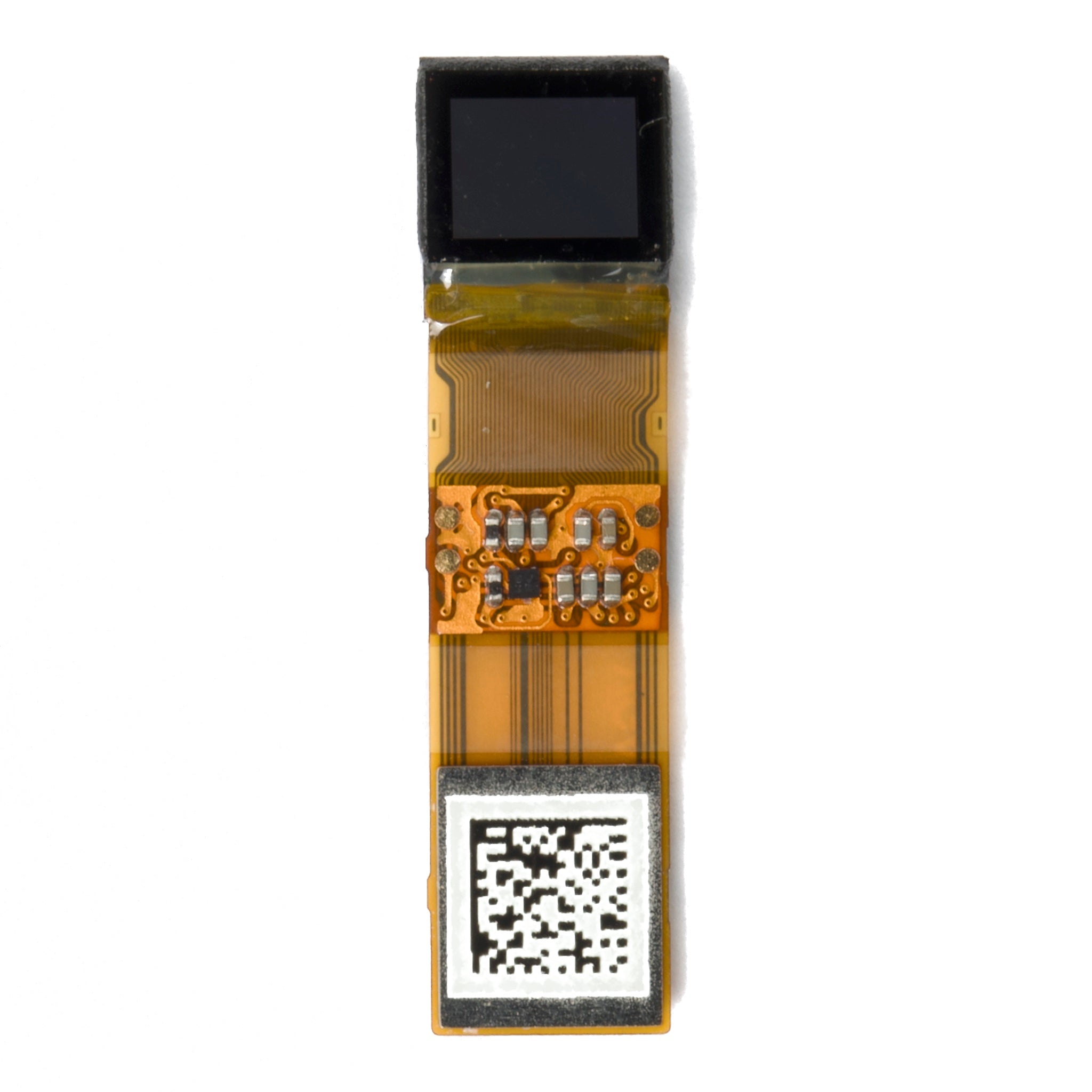
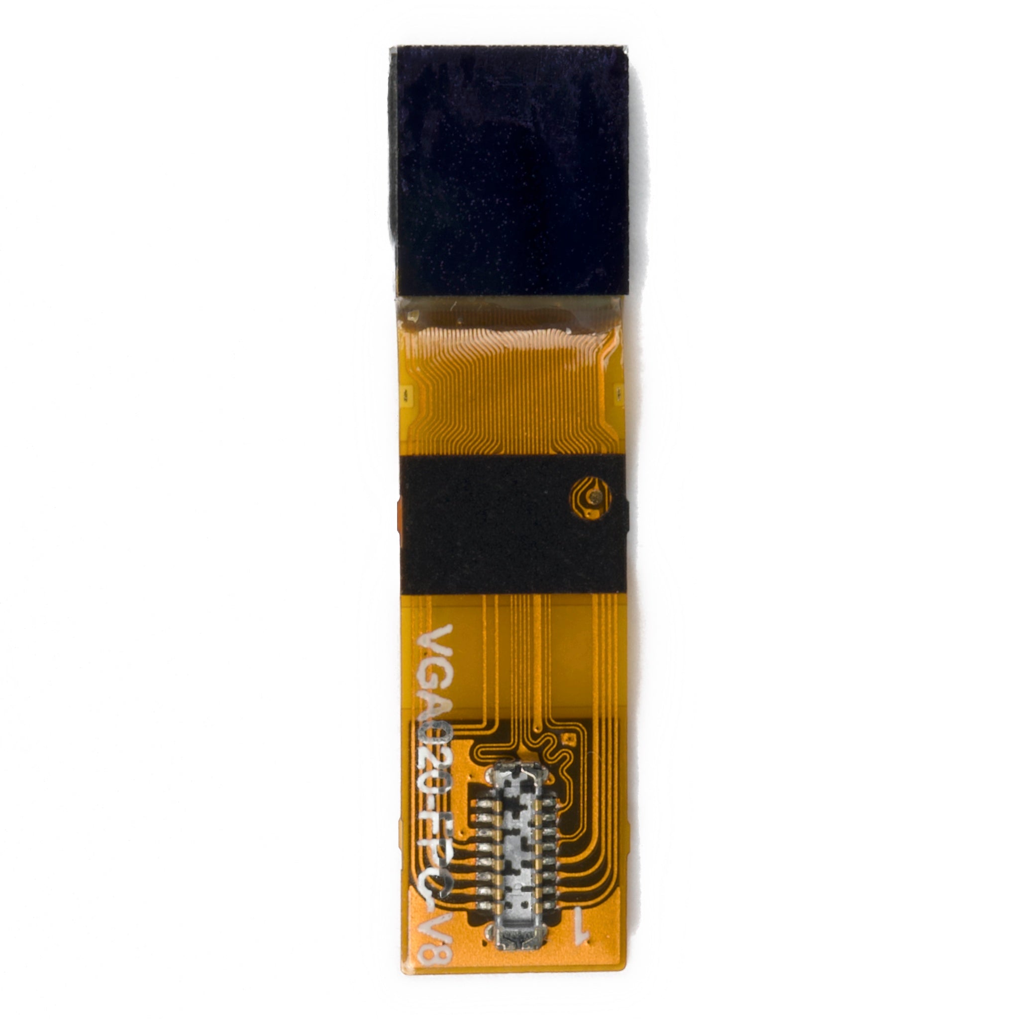
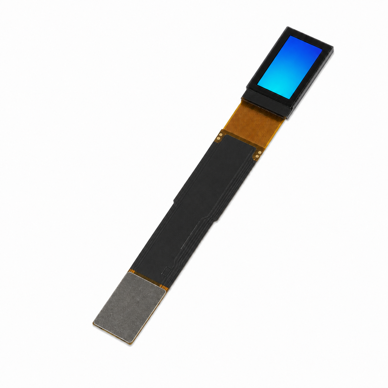
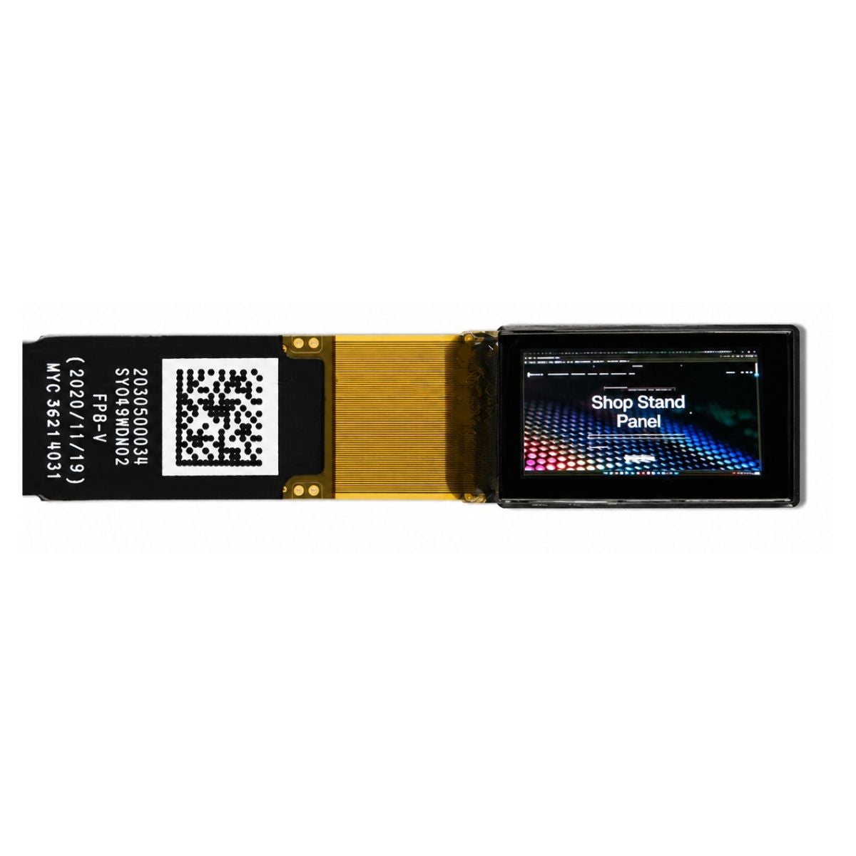
The flexible tail is where most custom designs lose time. Its thickness is set by the substrate, the copper and the coverlay, and the shape has to route around screw bosses, batteries and ribs without exceeding the minimum bend radius. A workable rule is an inside radius of six times the total thickness or more; a tighter fold puts the copper in tension and eventually cracks it.
Corners matter as much: right angles concentrate stress, so the outline should use generous arcs, and any fold line should run across the traces rather than along them. Where the tail terminates in a ZIF or BTB connector, a stiffener bonded behind the gold fingers gives the contacts something to clamp against and stops the fingers from deforming after repeated insertion.
Three details belong in the drawing, not in the process notes: gold finger finish and thickness, because wear life depends on it; clearance between the stiffener edge and the nearest copper, so the stiffener cannot peel and take traces with it; and a ground window for contact with a conductive frame, which gives electrostatic discharge a short path away from the driver.
Signal integrity on the tail
Once the interface is MIPI, LVDS or eDP, the tail stops being a wire and becomes a transmission line. Differential pairs are usually designed for 100 ohms, with tolerance stated as a percentage; the achievable tolerance depends on copper thickness, line width, dielectric thickness and the dielectric constant of the polyimide, so the stack-up has to be agreed before the artwork is drawn.
Intra-pair skew is the error that ruins an otherwise good layout. If the two lines of a pair differ in length, part of the differential signal converts to common mode, which radiates and eats margin at the receiver. Inter-pair skew matters too, because clock and data have to arrive within the same sampling window. Serpentine compensation should use shallow angles rather than right-angle jogs.
Keep a continuous reference plane under the pairs. A split or a slot forces the return current to detour, which raises loop inductance and shows up as ringing on the eye diagram. Where the stack-up allows, stitching vias beside signal vias give the return current a short vertical path between layers. For long tails or high lane rates, low-loss laminate or liquid crystal polymer is worth the cost; on a short tail inside a handheld enclosure it usually is not.

Setting backlight brightness
Brightness is a system number, not a panel number. The cell does not generate light, it modulates what the backlight supplies, so every brightness decision is really a decision about the light source and the optical stack[2]. What the user needs is enough luminance to hold contrast against the light falling on the screen, and the surface treatment changes that requirement more than the backlight does. A glossy front reflects several percent of ambient light; an anti-glare coating scatters it; optical bonding removes the air gap between panel and window that would otherwise create two reflecting surfaces.
An indoor instrument at a few hundred lux is comfortable at a few hundred nits, a shaded outdoor position needs considerably more, and direct sunlight needs both a bright backlight and control of reflection. Bonding and anti-reflection coating often deliver more readable improvement per unit of power than adding LEDs, because they raise the contrast the user sees rather than the light the panel emits.
Uniformity belongs in the specification. Measure a grid of points on a white field and divide the lowest reading by the highest; the ratio, not the centre brightness, is what a user notices on a pale background. State the measurement distance and the meter, because a reading taken close to the surface flatters the result; ISO 9241-307 sets out a procedure that makes the figure comparable[1].
Backlight electrical design
White LEDs are current-driven, and their forward voltage varies with bin and falls as the junction warms. A string is therefore designed around the worst-case voltage at the lowest operating temperature, with headroom left for the driver. Series strings keep the current common to every LED, which is the simplest way to keep brightness matched; parallel branches need either matched forward voltages or individual ballast, or the branch with the lowest voltage takes most of the current.
Constant-current boost drivers are the usual choice because efficiency holds up as string voltage climbs above the input; linear drivers are electrically quieter but burn the difference as heat, so they suit only low power. Whatever the topology, specify the dimming method: analog current reduction holds colour better at low levels, pulse-width modulation holds brightness linearity better, and a hybrid that switches between them avoids the colour shift that pure PWM can produce at very low duty cycles.
Flicker is a specification, not an opinion. A PWM frequency that is invisible in a lab can still be perceptible in peripheral vision or on a camera; a display photographed at a trade show is a marketing problem. Ask for the dimming frequency and the minimum duty cycle at the lowest brightness setting.
Heat and lifetime
Backlight LEDs lose output as junction temperature rises, and the loss compounds: driving harder to compensate adds heat. A metal-core or aluminium-backed board conducting into the housing does more for perceived brightness over a product's life than a higher-bin LED. Where the enclosure is sealed, the thermal path has to be designed rather than assumed, and the driver should fold back current above its limit.
Quote lifetime at the brightness and temperature the product will actually run, and state what the figure means.
Prototype verification
The first article should answer five questions. Does the module fit the enclosure without compressing the stack, since a squeezed backlight shows as bright patches or Newton rings? Is brightness within tolerance across the panel, measured on a grid? Does contrast hold under the intended ambient light, with the final window and coating? Does the interface run error-free at the specified lane rate over the production tail length, at both temperature extremes? And does current draw at representative content match the power budget?
Record the conditions with the results: instrument, distance, ambient illumination, temperature, and the pattern displayed. A verification report without conditions cannot be repeated, and a result that cannot be repeated is not a specification.
Documentation to lock
Release the drawing with the tolerance stack, the FPC stack-up and bend geometry, the LED bin and string configuration, the dimming scheme, and the interface timing. Then specify what the supplier must report per lot: brightness and chromaticity at defined points, and the results of the thermal and humidity tests agreed at qualification.
For standard cells, the TFT module collection covers common sizes and interfaces, and the industrial display collection lists wide-temperature parts. A COG character or graphic module is usually the cheaper starting point for text-only designs.
Custom work is mostly the discipline of deciding in the right order. Envelope, tail, optics, then electronics — reversing that sequence is what turns a two-week prototype into a two-quarter redesign.
References
- ISO 9241-307:2008 — Ergonomics of human-system interaction — Part 307: Analysis and compliance test methods for electronic visual displays. International Organization for Standardization. https://www.iso.org/standard/40102.html
- Hilsum, C. (2010). Flat-panel electronic displays: a triumph of physics, chemistry and engineering. Philosophical Transactions of the Royal Society A, 368(1914), 1027–1082. https://doi.org/10.1098/rsta.2009.0247
En lire plus

Graphic OLED achieves a million-to-one contrast ratio and 10-microsecond response time through self-emittance, while its 1.2mm ultra-thin modules support.

The 8080 parallel port gains high bandwidth by utilizing 8/16-bit lines, SPI reaches high-speed serial communication at 50MHz, I2C saves on pins, and RGB.
Laisser un commentaire
Ce site est protégé par hCaptcha, et la Politique de confidentialité et les Conditions de service de hCaptcha s’appliquent.