


Graphic LCD Technology | How It Works, Applications
Graphic LCDs control light transmission by regulating the alignment of liquid crystal molecules via voltage.
Operations require an MCU to write bitmap data to video memory, driving 128x64 dot matrix displays for complex graphics.
They are widely used in visual interactive interfaces for oscilloscopes and medical instruments.
How It Works
Graphic LCDs modulate light by precisely controlling the molecular alignment within a 4 to 7 micron liquid crystal cell gap.
Distinct from segment displays, it utilizes a grid of rows (Common) and columns (Segment) electrodes etched on ITO (Indium Tin Oxide) conductive glass for matrix addressing.
When the controller scans the electrodes with specific duty cycles (Duty 1/32 or 1/64) and bias ratios (Bias), the nematic liquid crystal molecules at the intersection points change their twist angle under the electric field, blocking or passing the backlight through 90-degree orthogonal polarizers.
The system operates in conjunction with driver ICs like KS0108 or ST7565, refreshing bitmap data in the DDRAM at frequencies above 60Hz, thereby presenting high-contrast dot matrix images.
Physical Stack Structure
The Bottom Light Emitting and Guiding Components
- Light Source: Nowadays, SMD LEDs (Surface Mount Device Light Emitting Diodes) are standard, with common package sizes being 0603 or 0805. To emit white light, blue LED chips are typically used to excite yellow phosphors, with color temperature controlled around 6500K.
- Light Guide Plate (LGP): This is a critical component, usually injection-molded from PMMA (Polymethyl Methacrylate), with a thickness between 2.0 mm to 3.0 mm.
- Dot Pattern Design: The bottom of the LGP features laser-etched or printed white reflective dots. The size and density of these dots are not uniform; dots usually get larger and denser the further they are from the LED to disrupt total internal reflection and "squeeze" light out of the surface, ensuring brightness uniformity across the display area exceeds 80%.
- Enhancement and Diffusion: A Diffuser and Prism Sheet (Brightness Enhancement Film) are stacked on top of the LGP. The diffuser scatters and atomizes the light to eliminate dot shadows; the prism sheet uses micro-prism structures to concentrate light towards the normal viewing angle, boosting frontal brightness by 30% to 50%.
The Bottom Polarizer Attached to the Back
- Material Composition: The core is a stretched PVA (Polyvinyl Alcohol) film that has adsorbed iodine molecules, which align directionally to form a grating.
- TAC Protection Layer: PVA is fragile and sensitive to water and heat, so a layer of TAC (Triacetyl Cellulose) film is attached to both the top and bottom sides to protect it, with a total thickness of about 0.2 mm.
- Transmission Axis Direction: The transmission axis angle of this film is fixed, for example, at 45 degrees or 135 degrees.
- Reflective Mode: If it is a reflective screen, an aluminum foil or silver reflective film is attached to the back of this polarizer to reflect ambient light directly, eliminating the need for a backlight module.
Two Pieces of Glass Sandwiching the Liquid Crystal
- Glass Material: Generally, alkali-free glass or soda-lime glass is used. It is very thin, with common specifications being 0.7 mm, 0.5 mm, or even 0.4 mm.
- Flatness Requirement: The flatness error of the surfaces of these two glass pieces must be controlled at the micron level because the thickness of the liquid crystal layer sandwiched between them is extremely sensitive.
- Sealant: The edges of the two glass pieces are bonded with epoxy resin glue to form a sealed box. The width of this glue ring is usually only 0.5 mm to 1.0 mm, leaving a tiny opening for injecting liquid crystal, which is sealed with UV glue after filling.
Invisible Conductive Circuits
- Sheet Resistance: This film is extremely thin, typically between 1000 to 1500 Angstroms (Å) thick. The metric for its conductivity is "sheet resistance"; for graphic dot matrix screens, the resistance is generally controlled at 10 to 15 Ohms/square.
-
Photolithography Etching: ITO does not cover the entire surface; factories use photolithography to etch away excess ITO, leaving stripes that serve as electrodes.
- Vertical stripes are etched on the bottom glass (Column Electrodes / Segment).
- Horizontal stripes are etched on the top glass (Row Electrodes / Common).
- The etched gaps are extremely fine, usually only 10 to 20 microns, almost invisible to the naked eye, and can only be faintly seen against the light.
The Groove Layer That Aligns Molecules
- Rubbing Process: This is a thin film (Polyimide/PI) with a thickness of only 500 to 1000 Angstroms. The factory uses a roller covered with velvet cloth (usually rayon or cotton) rotating at high speed to rub this film.
- Groove Function: Rubbing forms nano-scale micro-grooves on the PI film surface. These grooves act like lines in a "parking space," forcing the liquid crystal molecules contacting them to lie down at a specific angle and direction.
- Pre-tilt Angle: Liquid crystal molecules do not lie completely flat but have a lifting angle of 2 to 5 degrees (TN screens) or higher (STN screens).
Liquid Crystal and Support Spheres Injected in Between
- Gap Control: To ensure consistent screen thickness, countless tiny plastic or glass spheres called Spacers are sprinkled between the glass. Their diameter must be precise, usually 4 microns to 7 microns, with an error not exceeding 0.1 micron. Approximately 100 to 200 are distributed per square millimeter, acting as pillars to prevent the glass from collapsing.
- Liquid Crystal Mixture: The injected liquid crystal is not a single substance but a mixture of more than a dozen compounds. For STN (Super Twisted Nematic) screens, a Chiral Dopant is added to force the liquid crystal molecules to rotate 180 degrees to 270 degrees instead of the ordinary 90 degrees.
The Outermost Top Polarizer
- Orthogonal Angle: In Normally White mode, its angle is usually perpendicular to the bottom polarizer (90 degrees difference).
-
Surface Treatment: This film directly faces the user, so the surface usually undergoes special treatment.
- AG (Anti-Glare): Anti-glare treatment makes the surface micro-matte to diffusely reflect ambient light, preventing it from acting like a mirror.
- HC (Hard Coat): Hardened coating, with a hardness usually reaching 2H or 3H, prevents fingernails from scratching the screen.
Zebra Strips or FPC for Circuit Connection
- Zebra Strip: For simple modules, conductive rubber strips are used, consisting of alternating layers of conductive (carbon-filled) and insulating material. The spacing is very small (e.g., 0.18 mm), and they are pressed against the ITO pins on the glass edge by the mechanical pressure of the casing.
- COG + FPC: Higher-end graphic screens bond the driver chip directly onto the glass (COG process) and then connect a FPC (Flexible Printed Circuit) via ACF (Anisotropic Conductive Film) heat pressing. ACF contains gold-plated polymer conductive spheres (diameter 3 to 5 microns).
Electro-Optical Modulation Effect
The Initial Spiral State of Molecules
- Spatial Orientation Distribution: For the common TN (Twisted Nematic) mode, the bottom molecules align along the 0° direction, while the top molecules align along the 90° direction. This causes the liquid crystal molecules sandwiched in the 5-micron thickness to form a continuous spiral structure.
- Waveguide Effect Principle: When the wavelength of incident polarized light is much smaller than the pitch of the spiral structure, the liquid crystal layer exhibits optical rotation.
- Optical Rotation Parameter: After passing through the entire liquid crystal cell, the plane of polarization rotates exactly 90 degrees. In this state, light can smoothly pass through the top polarizer parallel to it (for Normally White mode), and the pixel's light transmittance reaches its maximum, typically maintained around 30% to 40% (limited by absorption loss of the polarizers themselves).
Molecules Standing Up After Voltage Application
- Threshold Voltage Range: The specific value depends on the dielectric anisotropy coefficient of the liquid crystal material.
- Molecular Alignment Transition: As the RMS voltage increases, the long axis of the liquid crystal molecules begins to overcome viscosity and align with the electric field. When the voltage reaches the Saturation Voltage, the vast majority of molecules, except for a very few close to the substrate, will stand perpendicular to the glass surface.
-
Disappearance of Phase Retardation: The liquid crystal layer loses its ability to rotate light, and the light maintains its initial polarization state upon reaching the top polarizer. Since the direction of the top polarizer is orthogonal to the light vibration direction at this moment, the light is largely blocked, transmittance drops to below 0.5%, and the pixel appears deep black.

Contrast Boost from Super Twist
- Twist Angle Expansion: STN liquid crystals increase the total twist angle of molecules from 90° to 180°, 240°, or even 270° by adding chiral dopants to the mixture.
- Steep Response Curve: Increasing the twist angle significantly changes the liquid crystal's Electro-Optical Characteristic Curve (V-T Curve). In STN structures, the voltage difference required for transmittance to drop from 90% to 10% is very small; tiny voltage fluctuations can drive molecules to flip extensively.
- Adaptability to Multiplex Driving: This steep characteristic allows the screen to maintain a clear brightness difference between "selected" and "non-selected" pixels even under high multiplex driving of 1/64 or even 1/128 duty cycles, with contrast typically reaching 10:1 to 20:1.
Millisecond-Level Game of Response Time
- Rise Time: The time from applying voltage to the molecules standing up completely. This depends on the electric field strength and the rotational viscosity of the liquid crystal. At a room temperature of 25°C, the rise time is usually 100 to 150 milliseconds.
- Fall Time: The time for molecules to return to the spiral state by their own elastic restoring force after the voltage is removed. This is usually slower than the rise time and may take 150 to 250 milliseconds.
- Temperature Influence: Below 0°C, the viscosity of the liquid crystal increases exponentially, and response time may extend to over 1 second, causing severe ghosting on the screen. Therefore, outdoor equipment often requires ITO heating glass to maintain photoelectric conversion efficiency.
Optical Shift Caused by Viewing Angle Switching
- Effective Birefringence Change: When users look at the screen from an angle, the path length of light passing through the liquid crystal increases.
- Contrast Inversion: At specific angles, pixels that should be black may turn white due to insufficient phase retardation compensation, or white backgrounds may darken.
- Compensation Film: To improve this, high-spec graphic LCDs add a layer of Compensation Film (e.g., FSTN) between the polarizer and the glass. This film has a specific phase retardation amount capable of canceling out the extra polarization rotation generated by large-angle incident light, extending the viewing angle from the traditional 30 degrees to over 60 degrees.
Matrix Scanning Drive
How Rows and Columns Cross
The bottom glass substrate distributes 128 vertical column electrodes (Segment), while the top glass substrate distributes 64 horizontal row electrodes (Common).
- Physical Characteristics of Intersections: The overlapping area of each row and each column is an independent pixel unit. The liquid crystal layer is sandwiched between these two electrode layers, acting as the dielectric of a capacitor.
- Pin Compression Efficiency: Through this matrix arrangement, controlling 8192 pixel points requires only 128 + 64 = 192 drive pins.
Duty Cycle: Making Current Queue Up
The Common Driver applies a strobe signal to each row sequentially in strict chronological order.
- Meaning of 1/64 Duty: For a 64-line screen, each row is selected for only 1/64 of the entire scanning cycle. If the refresh rate of the entire frame is 65Hz, the time spent on each row is only 0.24 milliseconds.
- Persistence of Vision Effect: Although each row of pixels is in a "powered off" state for most of the time, due to the physical response hysteresis of liquid crystal molecules and the integration effect of the human eye on brightness signals, the user perceives a continuous and stable image rather than flickering lines.
Voltage Allocation Method to Solve Crosstalk
In a matrix circuit, when applying electricity to a specific row and column, pixel points at non-target positions also sense weak charge interference.
- Bias Ratio Setting: To suppress this interference, driver chips introduce a multi-level voltage scheme. Common graphic screens adopt 1/9 Bias or 1/7 Bias.
-
Voltage Level Division: Drivers typically generate 6 different voltage levels (V0 to V5).
- Selected State: When the row electrode is at the selection voltage and the column electrode is at the display voltage, the voltage difference across the pixel reaches the maximum (e.g., 10V to 15V), and the liquid crystal molecules flip completely.
- Non-selected State: The system precisely controls the levels so that the voltage difference at other intersection points remains below the liquid crystal flipping threshold voltage (usually below 1.5V), ensuring non-target pixels remain static.
Pulse Control for Grayscale Display
Although monochrome graphic screens mainly handle black and white images, driving algorithms can simulate different shades, commonly known as FRC (Frame Rate Control) technology.
- Sub-frame Clock Frequency: The driver IC splits a complete display cycle into multiple finer sub-frames. For example, to display 50% gray on a point, the controller will make that pixel black for 2 frames and bright for 2 frames within 4 continuous frames.
- Data Throughput: When grayscale function is enabled, the controller's access frequency to DDRAM (Display Memory) doubles, typically requiring an interface clock frequency of 1MHz to 5MHz to ensure no visible flicker during rapid switching.
The Internal Porter of Driver Chips
Common graphic driver ICs like ST7567 or UC1601 integrate complex logic control units internally.
- Address Counter (AC): When the microcontroller (MCU) sends a byte of data via the serial interface (SPI), the internal AC automatically increments, storing data into the corresponding column address.
- Booster Circuit (DC-DC): Since logic circuits usually only provide 3.3V, while driving liquid crystal molecules requires higher voltage, the chip integrates a charge pump. By connecting 4 to 5 external 0.1 microfarad SMD capacitors, it can boost 3.3V to a driving voltage of 10V or more without requiring an external high-voltage power supply.
Temperature's Drag on Scanning Speed
Matrix driving is very sensitive to ambient temperature changes, determined by the viscoelastic coefficients of the liquid crystal.
- Viscosity at Low Temperatures: When the ambient temperature drops to -20°C, the viscosity of the liquid crystal increases by more than 10 times compared to room temperature. At this point, a 0.24 millisecond strobe pulse may not be enough for the molecules to complete the flip.
- Software Compensation Mechanism: High-end graphic display systems monitor temperature via an external NTC thermistor. When low temperature is detected, the driver IC automatically increases the driving voltage (Vop) and extends the scanning cycle, sacrificing refresh rate for image readability.
AC Scheme to Prevent Electrode Aging
If pixels are driven with a constant direction, the ITO electrodes will undergo electrolytic reactions, leading to screen failure.
- Phase Inversion Cycle: The row driver and column driver completely reverse voltage polarity after each frame ends.
- RMS Validity: Although positive and negative voltages alternate constantly, liquid crystal molecules perceive the Root Mean Square (RMS) value of the voltage. As long as the energy of the positive and negative pulses is equal, the molecules maintain the expected alignment state while ensuring electrolyte balance. This inversion typically occurs at a frequency of 80Hz to 100Hz to prevent interference with low-frequency signals.
Bias Preventing Crosstalk
Why Annoying Ghosting Occurs
The essence of crosstalk is false triggering caused by uneven voltage distribution.
- Drawbacks of Shared Paths: In a 128x64 screen, when you apply voltage to the 5th row and 10th column to light up that intersection, the other 127 pixels on the 5th row and the other 63 pixels on the 10th column are actually in a semi-energized state.
- Edge of Threshold Voltage: Liquid crystal molecules are extremely sensitive to voltage. If the induced voltage at non-selected points exceeds the starting flip voltage of the liquid crystal (usually around 1.0V to 1.3V), these molecules will deflect slightly.
- Visual Manifestation: To the user, this appears as faint black stripes around text, or when contrast is turned up, the entire screen background becomes grayish, failing to achieve true white.
Step Design of Multi-level Bias
To suppress these unwanted induced charges, driver ICs abandon simple binary 0 and 1 voltages in favor of a stepped voltage output called Multi-level Bias Scheme.
- Numerical Definition of Bias Ratio: Common graphic LCDs set 1/9 Bias or 1/7 Bias.
- Voltage Step Distribution: The resistor divider network inside the driver chip generates multiple intermediate levels, such as V1, V2, V3, V4, and V5.
- Cancellation Logic: When a row is selected, its level is at the highest (V0), while unselected rows are forced to stay at an intermediate level (like V4). Through this precise potential difference calculation, the system ensures that only the potential difference at the target intersection is far greater than the threshold, while the potential difference at all other non-target points is strictly limited within 30% to 50% of the threshold, keeping the molecules motionless.
Balance Brought by RMS Values
Liquid crystal molecules do not care about the positive or negative direction of voltage; they only react to the energy magnitude of the voltage, measured by the Root Mean Square (RMS) value.
- Selected Point Energy Density: Under 1/64 Duty drive mode, the selected pixel receives a high-energy pulse within the scanning cycle. Its RMS voltage must be maintained above 2.0V to 3.0V to ensure the liquid crystal flips completely.
- Non-selected Point Energy Suppression: Through bias circuit adjustment, the RMS voltage of non-selected points is suppressed to below 1.1V.
- Discrimination Ratio: This is a key performance indicator representing the ratio of RMS voltage between selected and non-selected points. For STN screens, this ratio usually needs to reach 1.1:1 or more to produce a clear image.
Logic of Software Contrast Adjustment
The "contrast" users adjust in the menu is essentially adjusting the total reference of the bias circuit.
- Vop Voltage Control: Contrast adjustment actually changes the output target of the DC-DC booster circuit inside the driver IC. For example, raising it from 9.0V to 9.5V.
- Dynamic Threshold Matching: As the total voltage Vop increases, all levels of bias rise proportionally.
- Overload Risk: If the contrast is set too high, the voltage at non-selected points will also cross the threshold line, causing the background to turn black.
Voltage Difference Drift Caused by Temperature Changes
Ambient temperature is the greatest enemy of the bias system because it alters the physical properties of the liquid crystal material.
- Threshold of Thermal Expansion and Contraction: When the weather is cold, liquid crystal viscosity increases, requiring higher voltage to rotate; when hot, molecules become active, and even small interference voltages can make them run wild.
- Automatic Temperature Compensation (ATC): High-spec drivers like UC1608 have built-in temperature sensors. When the temperature drops by 1°C, the chip automatically compensates the drive voltage by about -0.05% to -0.1%.
Cleanup of Charge Accumulation by Frame Inversion
Besides voltage magnitude, voltage direction switching plays an indirect role in preventing crosstalk.
- Ion Movement Restriction: Residual impurity ions in liquid crystal materials will move directionally under a constant electric field, causing local charge accumulation and creating pseudo-voltage differences.
- AC Drive Frequency: By switching positive and negative bias at a frequency of 70Hz to 80Hz, these ions oscillate in place, unable to form an electric field sufficient to interfere with pixels, thus maintaining potential balance on the electrode surface.
Reducing Interference from Wiring Resistance
Physical hardware wiring also affects bias accuracy.
- ITO Impedance Voltage Drop: The longer the ITO trace on the glass, the greater the resistance. If resistance is too high, voltage reaching the far-end pixels will attenuate, causing one side of the screen to be bright and the other dark.
- Compensation Wiring Design: When designing high-resolution graphic screens, engineers increase the metallization layer thickness at the pins or adopt dual-side driving to shorten the current path, ensuring that the loss of each bias signal during transmission does not exceed 5%, reducing crosstalk caused by voltage drop at the source.
Applications
Graphic LCDs (common specifications like 128x64 or 240x128) utilize dot matrix pixel technology, combined with controllers like ST7920 or KS0108, to present continuous waveforms and custom UIs.
Compared to screens that can only display text, they are more widely applied in equipment such as Fluke testers or Honeywell thermostats.
Relying on FSTN technology, they remain clear under strong outdoor light and can adapt to temperature changes from -20°C to +70°C.
Their power consumption is as low as the microampere (µA) level, making them suitable for devices relying on batteries for long periods, typically transmitting data via SPI or I2C interfaces.
Industrial Instrument Panels
Parameter Visualization for VFDs and Motor Drives
Taking ABB ACS880 or Danfoss VLT series frequency converters as examples, their control panels usually employ 128x64 or 240x128 pixel monochrome FSTN screens.
This resolution is just enough to draw dynamic curves of motor operation within limited physical dimensions (usually 2 to 3 inches).
- Real-time Load Monitoring: The screen displays current (Amps), torque (Torque), and speed (RPM) from the past 60 seconds as a scrolling line graph. Pixel points directly map ring buffer data in memory, refreshing 2 to 5 times per second.
- Soft Keys Layout: The bottom pixel rows of the screen are dedicated to displaying function labels for physical buttons.
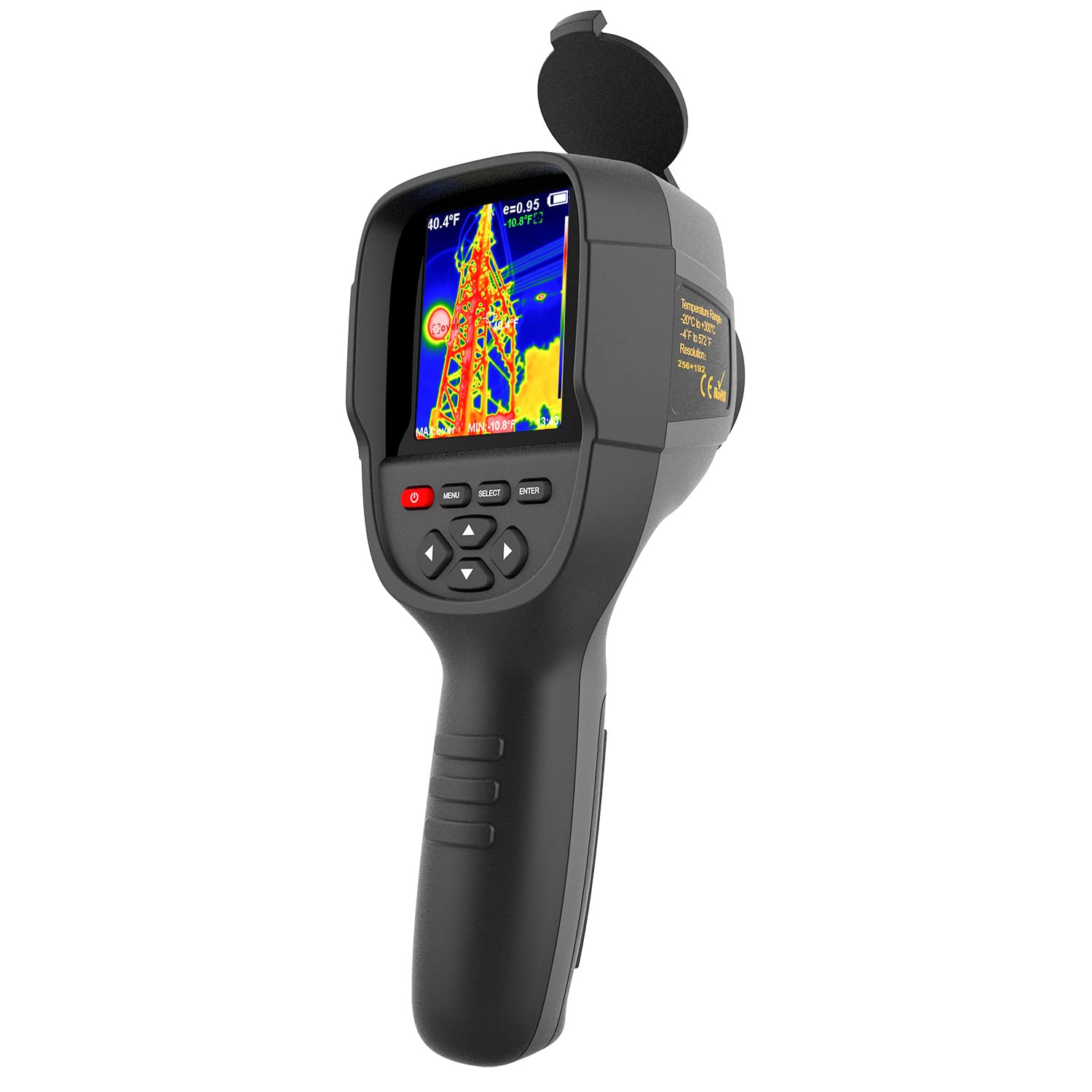
Power Quality Analysis and Handheld Testers
In power quality analyzers like Fluke 435 or Dranetz HDPQ, the role of graphic LCDs is not just displaying numbers, but serving as a terminal for on-site data analysis.
- Phasor Diagram Plotting: For three-phase electrical systems, technicians need to confirm the phase relationship between voltage and current. The graphic LCD uses trigonometric calculations to draw an origin in the center of the screen, radiating three vector segments representing phases. The pixel matrix can clearly show whether the angles of phases A, B, and C are balanced and if there are wiring errors.
- Harmonic Spectrum: The screen uses bar charts to display amplitudes from the fundamental wave up to the 50th harmonic. Each bar occupies 3 to 5 pixels in width, with height corresponding to the harmonic percentage. This high-density information display utilizes line drawing commands from controllers like ST7565 or T6963C to directly render spectrum distribution in low-power mode, helping to judge noise sources in the grid.
Graphical Feedback for Process Control Loops (PID)
In single-loop controllers from Honeywell or Yokogawa, the comparison between PV (Process Variable) and SP (Set Point) is core.
Graphic LCDs provide a display mode called "Bargraph" here.
- Dual Bargraph Comparison: The left side of the screen displays a solid bar representing current temperature or pressure (PV), and the right side displays a hollow frame or dotted bar representing the set target (SP).
- History Retracing: High-end model controllers utilize the remaining pixel area of the screen to draw the temperature trend of the past hour. The screen controller stores historical dot matrix data through internally integrated 64KB or larger RAM.
Hardware Adaptability in Harsh Environments
Graphic LCD selection for industrial dashboards must pass strict NEMA 4X or IP65 protection standard tests.
- Wide Operating Temperature Range: In standard consumer screens, liquid crystals become viscous below 0°C, causing slow refresh or failure to display. Industrial graphic LCDs use special liquid crystal material formulas, stretching the operating temperature range to -30°C to +80°C. In cold outdoor pumping stations, transparent ITO heating films are even integrated inside the screen, heating the liquid crystal layer to operating temperature by consuming 1-2 watts of power to ensure display content without ghosting.
- Sunlight Visibility (Transflective): Screens on outdoor generator sets or solar inverters must be readable under strong noon sunlight. Transflective technology uses external light reflection to illuminate pixels; the stronger the ambient light, the clearer the display. The backlight usually employs yellow-green or white LEDs, turned on only at night or in dim machine rooms. The LED half-life (brightness decay to 50%) is typically designed for 100,000 hours, equivalent to 11 years of continuous lighting.
Medical Handhelds
Visual Guidance for Automated External Defibrillators (AED)
Philips or Zoll devices utilize graphic dot matrix screens to play "frame animations" guiding electrode pad placement.
- Dynamic Pixel Rendering: AED screens typically adopt 320x240 or 128x64 resolutions. The controller pre-stores a set of bitmap sequences. When the system detects pads are not touching the skin, the screen loops a stick-figure animation of the "pasting action" at 5 to 10 frames per second. This black-and-white animation is not only more intuitive than text but also has near-zero startup time compared to video-playing color screens, displaying images within 200 milliseconds after system power-up.
- ECG Waveform Echo: For professional defibrillator monitors, the screen needs to draw the patient's electrocardiogram in real-time. The graphic LCD controller receives sampling data from the Analog Front End (AFE) via SPI interface. Usually, the screen is divided into two areas: the top 2/3 is used for waveform scrolling, where the controller uses "Read-Modify-Write" operations to write a new column of pixels to video memory while clearing the oldest column, forming a smooth scrolling effect; the bottom 1/3 is fixed to display heart rate values and battery status.
Insulin Pumps and Portable Infusion Devices
Medtronic or Roche insulin pumps need to be worn 24 hours a day, posing extreme challenges to screen energy efficiency.
- Microamp-level Power Management: Such devices are typically powered by a single AA battery and required to work continuously for 4 to 8 weeks. The current consumption of graphic LCDs during static display (not refreshing content, only maintaining display) can be controlled between 10 µA to 30 µA. In contrast, using OLED or color TFT, even at minimum brightness, background current would reach the milliamp (mA) level, shortening battery life to a few days.
- Basal Rate Configuration Charts: Doctors need to set the 24-hour insulin basal infusion rate for patients. Graphic LCDs allow the device to display hourly infusion amounts in the form of bar charts. Users can select specific "bars" via side physical buttons to increase or decrease. Each pixel height on the screen represents a specific drug unit (e.g., 1 pixel = 0.05 units). This visual configuration method prevents setting errors better than a simple list of numbers.
| Feature | Medical Grade Graphic LCD | Consumer Color Screen | Clinical Advantage |
|---|---|---|---|
| Standby Current | < 50 µA | > 20 mA | Allows device to power on for first aid even after months of warehouse storage |
| Sunlight Contrast | > 10:1 (Reflective Mode) | < 2:1 (Not only illegible but reflective) | No need to shade during outdoor accident scene first aid |
| Failure Mode | Missing segments or fading | Black screen or corrupted display | Even if the screen is damaged, remaining pixels can often still read partial data |
Handheld Pulse Oximeters and Multi-parameter Monitors
On Masimo or Nellcor handheld pulse oximeters, the graphic LCD undertakes the task of displaying the Photoplethysmogram (Pleth Waveform).
- Waveform Filling Algorithm: To let doctors see pulse strength from a distance, the waveform displayed on the screen is not just a single-pixel line but uses a "fill mode." The controller lights up all pixel points below the waveform curve, forming a solid black mountain-like graphic. This display method leverages the high contrast characteristics of FSTN screens (typically 15:1), increasing the visible area of fluctuations so medical staff can judge if the patient's Perfusion Index (PI) is normal with a glance, even in a dim ward.
- Reverse Display Mechanism for Alarm States: When oxygen saturation drops below 90%, the device not only sounds an alarm, but the screen controller also immediately executes a "Full Screen Reverse" or "Area Reverse" command. Originally white-background-black-text areas instantly become black-background-white-text and flash at a frequency of 1 Hz.
Hardware Durability in Harsh Environments
Medical equipment often requires cleaning with strong disinfectants and may encounter drops during ambulance transport.
- Chemical Resistant Polarizers: Ordinary screen polarizers easily yellow or bubble after contact with isopropyl alcohol or chlorine-containing disinfectant wipes. The surface of medical handheld LCD modules is usually covered with a specially treated glass or hardened acrylic (PMMA) protective layer, and polarizer materials undergo chemical resistance verification to ensure no optical degradation within 3 to 5 years when wiped 5 times a day.
- ESD/EMI Protection: In dry hospital environments, static electricity is a major issue. The metal bezel of medical LCDs is tightly grounded via conductive foam, capable of withstanding ±8kV contact discharge and ±15kV air discharge shocks, preventing static from breaking down screen logic. Simultaneously, to avoid interfering with sensitive equipment like pacemakers, LCD drive circuits adopt Low EMI designs, with slope control (Slew Rate Control) on clock signal rising and falling edges to reduce high-frequency harmonic emission.
Automotive and Marine
Graphic Rendering for Marine Fish Finders and Sonars
In small to medium marine electronics from Garmin or Raymarine, graphic LCDs are used to convert ultrasonic signals into underwater topography maps.
- Real-time Contour Drawing: Data streams returned by sonar sensors are sent to the LCD controller via high-speed SPI or parallel buses. The screen scrolls from right to left to display water depth in pixel units. The vertical position of each pixel point represents depth, while dot density represents echo strength. Through FSTN (Film Compensated Super Twisted Nematic) technology, the screen provides extremely high sharpness, enabling drivers to distinguish whether the bottom is soft mud or hard rock.
- Multi-window Split Screen: Since resolution can typically reach 240x128 or higher, the screen can be divided into multiple logical areas. The left area draws fish swimming trajectories dynamically with 2-pixel wide lines, while the right area uses large fonts (e.g., 16x24 dot matrix font) to display current speed (Knots) and water temperature (Celsius) in real-time.
Instrument Centers for Heavy Trucks and Engineering Vehicles
Between the mechanical tachometer and speedometer on truck dashboards, a monochrome graphic LCD is usually embedded as the Vehicle Information Center (VIC).
- Graphical Interpretation of Fault Codes: When the engine detects an abnormality, the screen no longer displays just a string of cold digital codes but draws relevant icons (such as exhaust system, turbocharger, or fuel filter) and flashes them. These pixel-matrix generated ISO 7000 standard icons can bridge language barriers, letting drivers immediately understand the approximate location of the fault.
- Liquid Level and Pressure Monitoring Bar Graphs: Heavy vehicles possess multiple air tanks and complex hydraulic systems. Graphic LCDs simulate a row of horizontal or vertical bars (Bar Graphs) to display brake air pressure (PSI) and Diesel Exhaust Fluid (DEF) levels. Each pixel height change represents a 0.5% liquid level fluctuation; compared to mechanical pointers, this display method saves significant dashboard space and doesn't produce physical jitter due to severe vehicle bumping.
Sunlight Non-reflective Marine Navigation
Sailing at sea, direct sunlight and sea surface reflection can cause ordinary color LED screens to turn completely black. Graphic LCDs use Transflective technology to solve this problem.
- Reflection Mode Utilizes Ambient Light: At noon, the screen backlight can be completely turned off, using the reflector behind to illuminate liquid crystal pixels with sunlight. The stronger the ambient light, the higher the black-and-white Contrast Ratio becomes, typically reaching 10:1 or more.
- Night Red Backlight Protection: In night navigation mode, to preserve the driver's dark adaptation (Night Vision), graphic LCD modules are usually equipped with red or amber LED backlights. Since the monochrome liquid crystal layer has a very high masking rate for light of different wavelengths, the light leakage rate is only about 0.1%, making the background very pure and not grayish like early TFT screens appearing at night.
Hardware Ruggedization Data for Extreme Environments
The installation environment of automobiles and ships dictates that LCD modules must possess a "constitution" far exceeding ordinary electronic products.
| Environmental Challenge | Technical Parameter Details | Actual Engineering Application |
|---|---|---|
| Ultra-low Temp Start | Response time less than 200ms at -30°C | Ensures oil pressure values are visible immediately upon startup in cold regions |
| Vibration Resistance | Withstand random vibration of 5G to 20G | Prevents diesel engine high-frequency vibration from causing display corruption |
| Salt Fog Corrosion | Passed 96-hour continuous salt spray test | Guarantees marine radios do not fail in high-humidity sea environments |
| ESD Protection | Withstand 15kV contact discharge interference | Prevents human static in dry cabs from damaging driver chips |
Driver Assistance and Sensor Feedback
In some vehicles equipped with parking assist or trailer hitching functions, graphic LCDs are used to display simplified distance perception maps.
- Ultrasonic Radar Schematic: The screen draws a top view of the vehicle and draws arcs of varying densities around the vehicle body. As the vehicle approaches an obstacle, the frequency of the arcs increases (changing from flashing once per second to steady on), and pixel blocks are filled to represent shortened distance. This simple geometric graphic feedback is more intuitive than voice alarms and can perceive distance accurately to the 10 cm level.
- Communication Bus Connection: These screens are usually mounted directly on the vehicle's CAN Bus or LIN Bus gateway. Through a microcontroller (like ARM Cortex-M0), the system unpacks complex bus protocol data packets and converts them into graphics instructions. Since the data transmission volume is far less than HD video streams, its occupancy rate of onboard network bandwidth is less than 1%, greatly improving overall system robustness.
Office and Home Appliances
Interactive Interfaces for Enterprise Telephones
Standard VoIP desktop phones from Cisco or Avaya widely adopt 192x64 or 240x128 pixel monochrome graphic screens.
- Dynamic Mapping of Soft Keys: The last 8 to 16 rows of pixels at the bottom of the screen are usually divided into 4 independent areas, directly corresponding to the physical buttons below the screen.
- Visualization of Call Status: The screen not only displays the other party's number but also shows the nature of the call through pixel icons.
-
Printer Fault Localization Map: On enterprise-grade laser printers from HP or Brother, graphic LCDs solve a pain point: telling the user where the paper jam is.
- Full Body Perspective Rendering: When a paper jam sensor triggers an interrupt signal, the controller reads the printer wireframe diagram stored in ROM and renders it on the screen. The specific location of the jam (such as the rear cover fuser assembly or Tray 2) will flash black pixel blocks at a frequency of 1Hz.
- Pixel-level Feedback of Consumable Levels: The screen usually reserves a specific area to display the status of 4 toner cartridges (CMYK). Using a 128x32 local area, the system draws 4 vertical bar charts. The pixel height filled inside each bar directly maps the remaining printable pages recorded in EEPROM. When toner is below 10%, the bar chart becomes a hollow frame accompanied by flashing; this fine remaining amount display is impossible for ordinary character screens.
Coffee Machine Brewing Animations
High-end fully automatic coffee machines (like select models from Jura or De'Longhi) use graphic LCDs to make complex extraction parameters easy to understand.
| Display Function | Pixel Representation Form | User Interaction Logic |
|---|---|---|
| Strength Adjustment | Displays 1 to 5 coffee bean icons | When rotating the knob, hollow beans are filled one by one to solid black, intuitively indicating increased powder amount |
| Cup Size Setting | Dynamically changes the size of the cup icon | Long press the button, the cup outline on the screen gradually grows until the user releases to lock the water volume |
| Maintenance Wizard | Animation demonstrating cleaning tablet insertion slot | Screen plays a stick-figure animation guiding the user to open the top cover and insert the cleaning tablet |
Such screens are usually used in conjunction with a Rotary Encoder.
When the user turns the knob, the highlighted cursor (reverse video area) on the screen jumps quickly between menu items, with a refresh rate usually maintained above 30fps to ensure smooth operation feel without ghosting.
Washing Machine Program Curves
On Whirlpool or Bosch washers and dryers, graphic LCDs are used to display the entire process of the washing cycle.
- Washing Stage Timeline: As the program runs, a thick black line advances along the timeline, and the icon for the current running stage enlarges or becomes bold. Users can know which stage the machine is in and how long it will take to finish with a glance at the screen.
- Dynamic Adjustment of Spin Speed: In the settings interface, the screen draws a semicircle resembling a tachometer. When the user adjusts the speed (e.g., from 800 rpm to 1200 rpm), the filled area within the semicircle changes accordingly.
- Moisture Resistant Design: Due to the humid working environment, LCD modules for home appliances are usually coated with a layer of Conformal Coating on the PCB surface, and the connection parts for the Zebra Strip are additionally sealed with glue to prevent moisture intrusion causing missing segments on the screen.
Thermostats and Smart Meters
Honeywell wall-mounted thermostats and Schneider smart meters rely on graphic LCDs to achieve "always-on" low-power display.
- 7-Day Temperature Programming Graph: Users need to set temperatures for different time periods within a week. The screen displays a coordinate system with time (0-24 hours) as the x-axis and temperature as the y-axis. The heating schedule set by the user forms a continuous line graph.
- Pie Chart for Time-of-Use Rates: On smart meters, the screen uses a circular pie chart to display whether the current time period is in the "Peak," "Flat," or "Valley" price range. The larger the black fan-shaped area, the more expensive the current electricity price. Such screens usually adopt COB (Chip On Board) packaging technology, encapsulating the driver chip directly on the back of the glass to achieve complex graphic display functions at extremely low cost, and power consumption when fully lit typically does not exceed 100 microwatts (µW).
En lire plus
When selecting a model, use I2C or SPI for low-speed interfaces, and RGB or Parallel interfaces for high-speed ones; Select a resolution of 128x64 or higher based on display precision requirements;...
Character LCDs, such as the 1602, display only fixed ASCII codes, featuring low cost and simple interfaces; Graphic LCDs, such as the 12864, can independently control pixel points to draw curves or...
Laisser un commentaire
Ce site est protégé par hCaptcha, et la Politique de confidentialité et les Conditions de service de hCaptcha s’appliquent.