


How to Choose a TFT LCD | Interface, Brightness & Viewing Angle Guide
Under strong outdoor light, you should choose an IPS panel with brightness above 800 nits and a 178° viewing angle.
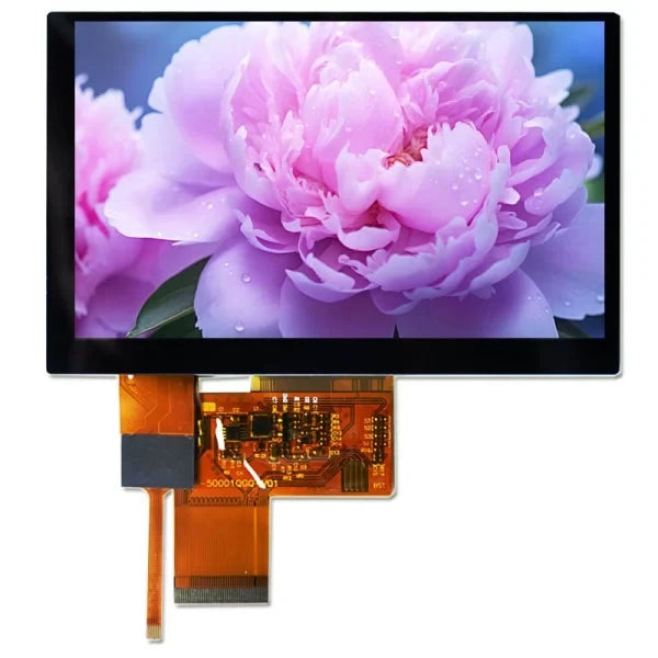
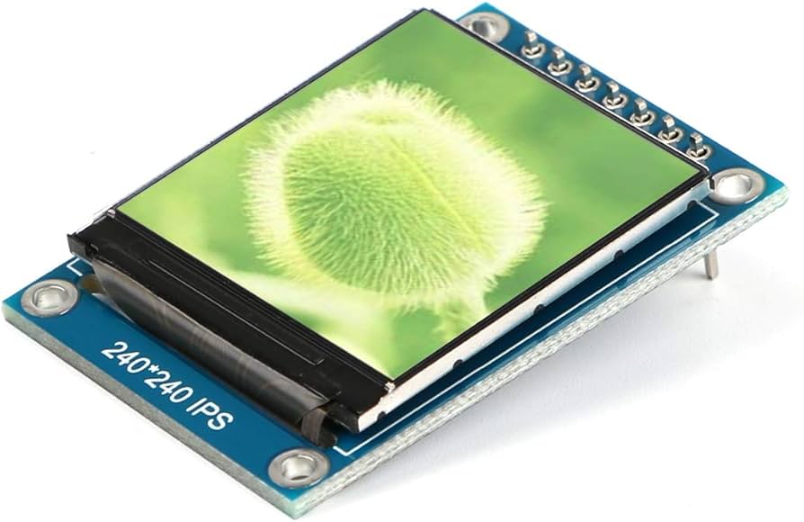
For low-speed display use SPI; for high-definition video streams you must use a MIPI interface to ensure smoothness.
Interface
For an 800x480 panel, 24-bit color depth, 60Hz refresh rate, the data generated per second is approximately 553 Mbps.
SPI interface typically supports speeds below 50 Mbps and is only suitable for static UI; RGB interface can achieve parallel transmission, but more than 40 signal lines will cause EMI issues;
LVDS and MIPI use differential signaling technology, boosting bandwidth to the Gbps level while reducing pin count, respectively addressing long-distance industrial transmission and high-resolution display needs in consumer electronics.
Bandwidth and Data Rate
Calculate How Much Data You Actually Need to Transmit
Looking at resolution alone is not enough; you must introduce the concept of the Blanking Interval.
When a screen displays an image, the “beam” or data pointer needs time to move from the end of one line to the beginning of the next (H-Blanking), and from the end of one frame back to the top-left corner (V-Blanking).
During this time no pixels are shown, but the interface clock must keep running.
The actual Pixel Clock calculation is as follows:
Pixel Clock = (H_Active + H_Blanking) * (V_Active + V_Blanking) * Refresh Rate
Using a common 800x480 resolution and 60Hz refresh rate as an example:
- Horizontal Active Pixels (H_Active): 800
- Horizontal Blanking (H_Blanking): typically about 256 (including HFP, HBP, Hsync)
- Vertical Active Pixels (V_Active): 480
- Vertical Blanking (V_Blanking): typically about 45 (including VFP, VBP, Vsync)
The actual clock requirement is not 800*480*60 = 23MHz, but (800+256) * (480+45) * 60 ≈ 33.2 MHz.
If the interface cannot provide a stable 33.2 MHz clock, the frame rate will drop below 60Hz.
For 1920x1080 (FHD), including blanking overhead, the pixel clock usually needs to reach 148.5 MHz.
Why SPI Can’t Refresh Large Images Smoothly
The SPI interface is limited by its serial transmission mechanism and GPIO toggle speed.
Standard SPI is 1-bit wide. Transmitting one 16-bit (RGB565) pixel requires 16 clock cycles.
Assume the host SPI clock is configured to 50 MHz:
- Theoretical maximum pixel fill rate: 50,000,000 / 16 ≈ 3,125,000 pixels/second.
- Driving a 320x240 display: 76,800 pixels per frame. 3,125,000 / 76,800 ≈ 40.6 fps.
- Driving a 480x320 display: 153,600 pixels per frame. 3,125,000 / 153,600 ≈ 20.3 fps.
If you use QSPI (Quad-SPI), the data lines increase to 4, and the theoretical speed increases by 4x, which can improve static display at 800x480 resolution, but video playback is still difficult because you must also account for the overhead of sending commands and addresses.
The Speed Bottleneck of the MCU 8080 Parallel Bus
The MCU parallel bus (such as a 16-bit 8080 bus) transfers one pixel per write cycle. The speed depends on the host’s FSMC/EXMC bus timing.
A standard write cycle includes: CS low -> WR low -> data setup -> WR high -> CS high.
This process is limited by the capacitive load of the IO pins and the slew rate. On common MCUs like STM32, the fastest write cycle is typically between 33ns ~ 66ns.
- If the write cycle is 66ns, the frequency is about 15 MHz.
- For an 800x480 panel, pure pixel transfer (without blanking) needs 800*480*60 = 23 MHz bandwidth.
- A 15 MHz bus speed cannot support 800x480 @ 60Hz.
This is why MCU-interface panels rarely exceed 4.0 inches or 800x480 resolution.
Parallel Interference Issues of the RGB Interface
The RGB interface (TTL) is parallel transmission. Common modes include 16-bit (RGB565), 18-bit (RGB666), and 24-bit (RGB888).
In RGB888 mode, including control signals, there are 28+ signal lines toggling simultaneously.
When resolution increases to 1024x600, the Pixel Clock is about 51 MHz.
- At 51 MHz, 20+ lines switch between 0 and 3.3V.
- Crosstalk: adjacent wires on the FPC create coupling capacitance; voltage changes on one line interfere with neighboring lines.
- Skew: small differences in routing length cause 24-bit data to arrive at the panel at slightly different times.
How LVDS Uses Low Voltage to Run at High Speed
LVDS (Low Voltage Differential Signaling) solves two pain points of the RGB interface: too many pins and limited frequency.
It uses serialization to compress parallel RGB data onto a few differential pairs.
- 7:1 serialization: within one clock cycle, an LVDS data lane transmits 7 bits.
- If the pixel clock is 50 MHz, the physical frequency on the LVDS data lane can be as high as 50 * 7 = 350 Mbps.
- Low swing: to reach that speed, LVDS does not use 3.3V levels, but a low-voltage differential signal of about 350mV.
A common LVDS 5-pair (single-channel 8-bit) interface can easily run a 85 MHz pixel clock, supporting 1366x768 resolution.
With dual-channel LVDS, two channel groups work simultaneously, doubling bandwidth, supporting 1920x1080 @ 60Hz.
Multi-Lane Throughput of MIPI DSI
MIPI DSI uses the D-PHY physical layer, originally designed to handle the terrifying bandwidth demands of FHD (1920x1080) and even 4K panels.
MIPI bandwidth is accumulated by Lane:
- Single-lane rate: under MIPI D-PHY v1.1, a single lane is typically 500 Mbps ~ 1.0 Gbps. Newer hosts may support up to 1.5 Gbps / lane.
- Packet overhead: MIPI is packet-based; besides pixel data there are headers, ECC, etc. Effective bandwidth is typically about 80% ~ 90% of the physical bandwidth.
SPI and MCU
Why These Two Interface Types Require the Screen to Have Its Own Memory
Unlike the RGB interface, these two interfaces have limited bandwidth and cannot withstand the real-time “bombardment” of full-screen data 60 times per second.
The solution is to integrate a GRAM (Graphics RAM, video memory) inside the LCD module.
- RGB interface: the host continuously sends data; the panel shows whatever it receives. Stop sending and the screen goes black or freezes on the last frame.
- SPI/MCU interface: the host writes data into the panel’s GRAM; the driver IC scans GRAM internally and refreshes the panel by itself.
The Debate Between 3-Wire and 4-Wire SPI
On engineering schematics, SPI panel pin definitions often confuse people because the industry has several wiring variants, mainly differing in how they distinguish commands and data.
-
4-Wire SPI (most common)
- Pins: CS (chip select), SCLK (clock), MOSI (data), and D/C (data/command select).
- Mechanism: the high/low level of the D/C pin directly tells the panel whether the bus is carrying pixel data or configuration commands.
- Efficiency: highest.
-
3-Wire SPI (9-bit mode)
- Pins: CS, SCLK, MOSI. No D/C pin.
- Mechanism: uses a data bit to distinguish. Standard 8-bit transfers are extended to 9 bits. The first bit is the D/C flag; the remaining 8 bits are the actual data.
- Cost: the host SPI hardware usually supports only 8-bit or 16-bit transfers. To send 9-bit data, you often must bit-bang GPIO in software, which is extremely slow.
The Real Overhead of SPI Data Transmission
The key is the number of clocks needed to transmit one pixel (Clocks per Pixel, CPP).
Assume standard 16-bit color depth (RGB565):
- Standard SPI: 1 clock transfers 1 bit. Transmitting 1 pixel needs 16 clock cycles.
- Bandwidth utilization: if SPI clock is 40MHz, the actual pixel fill rate is only 2.5M pixels/s.
Calculate screen refresh time (40MHz clock):
- 240x240 (1.3"): 57,600 pixels x 16 clocks / 40,000,000 = 23ms, i.e., about 43 FPS. This is smooth.
- 320x480 (3.5"): 153,600 pixels x 16 clocks / 40,000,000 = 61ms, i.e., about 16 FPS. You can feel the stutter.
QSPI (Quad-SPI) steps in
To rescue performance, some driver ICs (such as ST7796 or certain versions of GC9A01) support QSPI, using 4 data lines in parallel.
- Speed boost: 1 clock transfers 4 bits; 1 pixel needs only 4 clocks.
- Result: theoretical frame rate improves 4x. But on low-end MCUs, QSPI is often used for flash reads, and dedicated QSPI ports for pushing pixels are less common.
The Bit-Width Trap of the MCU 8080 Parallel Port
The MCU interface (also called System Bus Interface) inherits the Intel 8080 bus protocol. Its advantage is parallel transmission.
- 8-bit mode: data lines D0-D7. Transmitting one RGB565 pixel requires 2 writes (high byte then low byte).
- 16-bit mode: data lines D0-D15. Transmitting one RGB565 pixel requires only 1 write. Efficiency doubles.
- 18-bit mode: data lines D0-D17 for RGB666. Colors improve, but to align with MCU registers (usually 8/16/32-bit), software handling becomes awkward and often wastes CPU cycles.
Write Timing and the WR Pin Bottleneck
Whether an MCU interface is fast depends not on CPU frequency but on the toggle speed of the WR (Write) pin.
A standard write cycle includes:
- Pull CS low.
- Establish levels on data lines (D0-D15).
- Pull WR low (strobe).
- Pull WR high (latch; the panel latches data on the rising edge).
The panel driver IC datasheet specifies a parameter: Write Cycle Time (Twc).
- Older driver ICs (e.g., ILI9325): minimum Twc is about 100ns, i.e., a 10MHz limit.
- Modern driver ICs (e.g., ILI9488 / ST7789): Twc can reach 30ns or even lower.
If the MCU’s GPIO toggling is not fast enough, or if FSMC (static memory controller) timing is too conservative and the WR pulse width is too large, a lot of time is wasted.
On STM32-class chips, using DMA (Direct Memory Access) together with FSMC/EXMC is essential.
If you bit-bang timing using GPIO, CPU usage will hit 100% and frame rates will be very low.
Tearing and the TE Signal
On SPI and MCU interfaces, tearing is a classic issue.
This happens because the speed of writing GRAM and the panel’s internal scanning speed to refresh the glass are not synchronized.
When the panel is halfway through reading, if the host rewrites that area, the top half shows the old frame and the bottom half shows the new frame, creating a misaligned seam.
The TE (Tearing Effect) pin exists to solve this.
- Function: the driver IC outputs a pulse on TE to tell the host: “I just finished scanning a frame and I’m in V-Blanking—write now!”
- Sync strategy: once the host detects TE toggling, it immediately starts DMA to transmit data. As long as transfer time is shorter than V-Blanking + display time, you can avoid the scan lines perfectly and achieve silky animations.
- Cost of ignoring it: many beginners omit TE to save a GPIO. During fast UI animations, this causes obvious diagonal tearing patterns.
RGB TTL Interface
This Interface Has No “Brain”
LCD panels defined by the RGB interface are “Dumb Panels.”
This term is not derogatory; it means the panel contains no video memory (GRAM) and no controller capable of holding an image.
It is like a pure executor: the host sends a pixel signal, and it lights a dot.
Once the host stops sending data, the image disappears immediately or freezes as a ghost of the last frame.
The host must allocate a Framebuffer region in memory, then use the LCD controller with DMA to tirelessly move pixel data from memory to the GPIO bus.
Using the most common 800x480 resolution, 24-bit color (RGB888) 5.0-inch panel as an example:
- Framebuffer size: 800 * 480 * 3 bytes ≈ 1.15 MB.
- This directly “sentences” most microcontrollers. For example, STM32F103 has only 64KB internal SRAM and cannot store even one full frame.
- Therefore, RGB-interface designs typically require: external SDRAM or DDR, or a host SoC with MB-level internal SRAM.
Dozens of Wires Running in Parallel
The biggest feature of RGB is too many wires. It uses parallel transmission: the data for red (R), green (G), and blue (B) channels is sent simultaneously.
Depending on color depth, the number of data lines differs:
- RGB565 (16-bit): R5 + G6 + B5, totaling 16 data lines. Gradients are average; commonly used in low-cost solutions.
- RGB666 (18-bit): R6 + G6 + B6, totaling 18 data lines. This is the most common configuration for the 40-pin “standard” interface (many 40-pin modules expose only RGB666 even if the panel supports RGB888).
- RGB888 (24-bit): R8 + G8 + B8, totaling 24 data lines. This is the mainstream configuration for 50-pin interfaces, offering the best color reproduction (16.7M colors).
In addition to data lines, you must add control signals:
- DCLK (Dot Clock): pixel clock; each pulse represents one pixel transfer.
- HSYNC (Horizontal Sync): tells the panel “this line is done; go to the next.”
- VSYNC (Vertical Sync): tells the panel “this frame is done; return to the top-left.”
- DE (Data Enable): high means the data on the bus is valid; low means blanking.
Altogether, a standard RGB888 interface needs at least 28 signal lines (24 data + 4 control).
If you route this on a PCB, you must manage 28 equal-length traces.
If these traces differ in length, the arrival times differ slightly (skew), leading to color misalignment.
DE Mode or SYNC Mode?
When configuring RGB drivers, you often see a choice between DE Mode and HV Mode (Sync Mode).
- HV Mode (Sync Mode): traditional timing mode. The panel fully relies on HSYNC and VSYNC to locate scan positions.
- DE Mode: modern TFT LCDs prefer this. The panel isn’t very concerned with HSYNC/VSYNC; it mainly looks at DE. If DE is high, it accepts data and draws; when DE is low, it changes line or waits.
- Advantage: DE mode has higher timing tolerance. Some panels can even ignore HSYNC and VSYNC pins in DE mode, saving 2 GPIOs.
Frequency Ceiling and the Interference Storm
RGB uses TTL levels, typically 3.3V. More than 20 bus lines continuously switch between 0V and 3.3V at full swing.
As resolution increases, pixel clock (DCLK) rises rapidly:
- 480x272 @ 60Hz: DCLK about 9 MHz.
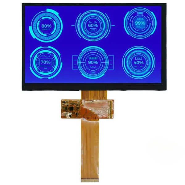
- 800x480 @ 60Hz: DCLK about 33 MHz.
- 1024x600 @ 60Hz: DCLK about 51 MHz.
Around 50 MHz, 24 parallel 3.3V lines become 24 “transmit antennas.”
- EMI: radiation is very strong, easily causing EMC test failures.
- Crosstalk: FPC pitch is tight (often 0.5mm). Data transitions on R can couple into G, causing ripples or noise.
- Ground bounce: when all data lines switch from 0 to 1 simultaneously (e.g., displaying white), instantaneous current spikes cause ground plane voltage fluctuation and system instability.
The industry’s “safe red line” is usually around 1024x600 or 1280x800.
Once you exceed that, or if cable length exceeds 15–20 cm, signal integrity becomes hard to guarantee and you must switch to LVDS or MIPI low-voltage differential interfaces.
Brightness
Typical indoor office monitors are usually 250 to 300 nits, sufficient for general lighting conditions.
If the device must be used in semi-outdoor environments or under strong lamps, brightness should increase to above 500 nits.
For outdoor devices under direct sunlight, 1000 nits is the baseline to ensure readability.
During selection, note that high brightness will multiply LED backlight power consumption and heat generation.
Typically, industrial LED backlights have a half-life (time for brightness to decay to 50%) of 30,000 to 50,000 hours.
Scenario-Based Brightness Levels
Ambient Light and Screen Brightness
Human perception of brightness is not absolute but relative. What we perceive as “clear” depends on the battle between the screen’s emitted light (nits) and ambient reflected light.
Ambient illuminance is usually measured in Lux. To keep content readable, the screen must provide enough contrast.
General engineering rules of thumb suggest that to achieve a comfortable reading experience, Ambient Contrast Ratio (ACR) should be at least 5:1; to clearly show full-color images, ACR is better above 10:1.
The table below shows brightness baselines required to maintain basic readability under different ambient illuminance levels:
| Environment Scenario | Ambient Illuminance (Lux) | Recommended Screen Brightness (Nits) | Contrast Challenge Level |
|---|---|---|---|
| Dark room | 0 - 50 | 5 - 50 | Very low (avoid glare) |
| Typical office | 300 - 500 | 250 - 350 | Low |
| Mall / Operating room | 500 - 1,000 | 500 - 800 | Medium (anti-glare needed) |
| Outdoor shade | 1,000 - 10,000 | 800 - 1,200 | High |
| Direct sunlight | 30,000 - 100,000 | 1,500 - 2,500+ | Very high (strong thermal design required) |
Dark or Low-Light Environments
If a standard-brightness screen is used in a fully dark environment (0 Lux)—for example, its minimum brightness can only be adjusted down to 100 nits—drivers or operators may experience an instant flash blindness effect, making it hard to see the surroundings.
- Dimming range: for such applications, the TFT LCD backlight driver must support wide-range dimming. A brightness ratio of 1000:1 or higher is commonly required.
- Technical indicators: If the frequency is below 200Hz, flicker may be perceived at low brightness, causing visual fatigue. High-end applications typically require hybrid dimming (DC dimming + high-frequency PWM) to ensure stable images and color fidelity in the 0.5 nits to 50 nits range.
Standard Indoor Office Use
This is the most common scenario, including industrial HMI, indoor ATMs, and medical monitors.
- Baseline: most standard industrial screens ship at 250 nits to 350 nits.
- Design logic: typical indoor artificial lighting is around 400 Lux. A 300-nit screen can provide 10:1+ contrast. If you force a 1000-nit high-bright screen here, it not only increases cost; excessive brightness can also cause discomfort due to pupil constriction and make the image look “washed out.”
Strong Indoor Lighting
Typical examples include surgical displays and shopping mall window signage.
- Operating room: surgical lamps can reach extremely high illuminance, often 20,000 Lux to 100,000 Lux in the focused area. Even if the display is not directly under the lamp, ambient reflections are strong. Medical displays typically require stable brightness of 600 nits to 800 nits, combined with AG (Anti-Glare) treatment to diffuse reflections.
- Showcase windows: digital signage facing the street is indoors but receives sunlight through glass. If brightness is only 350 nits, the screen looks almost black at noon when viewed from outside. Such applications should start at 700 nits, plus a light sensor for automatic brightness adjustment based on outdoor sunlight.
Outdoor Shade and Indirect Sunlight
This level covers devices under canopies, such as gas pumps, semi-outdoor ticket machines, or engineering vehicle instruments with sunshades.
Although there is no direct sunlight, skylight is strong, typically 2,000 Lux to 10,000 Lux.
- Brightness threshold: 800 nits is the minimum; 1000 nits is ideal.
- Reflection handling: at this level, brightness alone is barely enough; you must consider surface reflectance. Standard air-bonding (air gap) assemblies can reflect about 13%–15% of light.
- Energy efficiency: backlight power rises significantly. For example, a 10.1" panel going from 300 nits to 1000 nits may raise backlight current from 200mA to over 600mA.
Challenges Under Direct Sunlight
On a clear midday, direct sunlight can reach 100,000 Lux.
To read content under such illumination, there are generally two technical routes:
-
Super high brightness
- Spec requirement: typically 1500 nits to 2500 nits or higher.
- Thermal management: the biggest engineering obstacle. Sunlight has strong thermal radiation (infrared), and full-power LED backlight adds its own heat; the panel surface temperature can easily exceed 80°C.
- Blackening threshold: standard LC materials may undergo phase changes at high temperature, causing the screen to blacken (Clearing Point). Direct-sunlight outdoor panels must use wide-temperature liquid crystal with a clearing point often up to 110°C to prevent “heat stroke” under exposure.
-
Limitations of Transflective technology
- Although transflective panels use reflected sunlight to enhance brightness, their transmittance is usually low, reducing backlight efficiency.
- Color compromise: because part of the pixel structure is used for reflection, color gamut is often only 40%–50% of a normal transmissive panel.
Sunlight-Readable Technologies
Do the Contrast Math
To quantify “visibility,” you must compute Effective Contrast Ratio.
The formula is simple:
ECR = (Screen Luminance + Reflected Luminance) / Reflected Luminance
- Screen luminance: white luminance (nits) with backlight at maximum.
- Reflected luminance: Ambient lux × total reflectance (%) / 3.14 (approximation).
Measured data comparison: assume ambient illuminance is 30,000 Lux (typical outdoor cloudy-to-sunny), compare two configurations:
| Configuration | Standard screen (no treatment) | High-end outdoor screen (full bonding + AR) |
|---|---|---|
| Panel brightness | 1000 nits | 1000 nits |
| Total reflectance | 15% (3 reflective interfaces) | 0.5% (AR + bonding) |
| Reflected luminance | ~1,430 nits | ~48 nits |
| Computed contrast | 1.7 : 1 | 21.8 : 1 |
| Visual result | Almost unreadable, gray and hazy | Crisp and sharp, good color reproduction |
Fill the Air Gap
In standard assembly (frame tape / air bonding), there is a 0.3mm - 0.5mm air layer between them.
- Physical flaw: when light passes through glass (n=1.5) -> air (n=1.0) -> glass (n=1.5), each interface produces about 4% Fresnel reflection due to the refractive index jump. With three interfaces (outer cover, inner cover, LCD surface), total reflectance can easily exceed 12%.
- Solution: Optical bonding, filling the air gap with optical adhesive (OCR liquid or OCA film) with a similar refractive index of about 1.5.
-
Engineering benefits:
- Eliminate internal reflections: reflectance drops by 8% - 10%.
- Prevent condensation: without an air layer, fogging inside the glass is avoided during outdoor temperature swings.
- Improved shock resistance: cured adhesive increases structural strength, making IK07/IK08 impact tests easier to pass.
Brute-Force Improve Backlight Efficiency
If contrast is still insufficient after reducing reflectance, you must increase source brightness. But “high brightness” is not just “add more LEDs”; it involves pushing optical efficiency to the limit.
-
Brightness enhancement films (BEF & DBEF)
Standard TFT LCD backlight utilization is very low (about 5%–8%). After the rear polarizer, P-polarized light passes while S-polarized light is absorbed as loss.
- DBEF (Dual Brightness Enhancement Film): placed below the polarizer; it does not absorb S-polarized light but reflects it back into the backlight module, where scattering turns it into random polarization again for reuse.
- Data: adding just this film can boost brightness by 30% - 40% without increasing power. This is standard for 1000+ nits screens.
-
The deadlock between thermal design and lifetime
- Thermal droop: LED efficacy decreases as temperature rises. For every 10°C increase in junction temperature, luminous flux may drop 2%–5%.
- Wide-temperature liquid crystal: ordinary LC reaches clearing point at 70°C - 80°C, turning isotropic and blackening. Outdoor high-bright panels must use Hi-Tni LC material to raise the clearing point to 110°C, resisting both solar IR heating and backlight self-heating.
Transflective: Borrowing the Sun’s Power
Instead of fighting the sun, use it. This is a special panel that changes the pixel’s physical structure.
-
Pixel architecture: each pixel cell is physically split into two regions.
- Transmissive region: has backlight behind it, for dark environment display.
- Reflective region: includes a micro-reflector layer (usually aluminum or silver alloy) that uses incoming ambient light to illuminate the pixel.
-
Performance characteristics:
- Adaptive brightness: stronger ambient light produces stronger reflection, making the screen brighter. In midday sun, the backlight can be fully off and power can approach zero.
- Drawbacks: because the pixel area is split, the transmissive area shrinks, lowering backlight efficiency (not bright enough in dim conditions). Reflected light passes through the color filter twice (in and out), causing heavy spectral absorption; color saturation (NTSC) is often only 40% - 50% of ordinary panels, so colors look washed out.
- Current status: due to poor color performance, besides professional handheld GPS devices, radios, and some aviation instruments, transflective panels have gradually been replaced in consumer and commercial display by high-bright IPS + full bonding solutions.
Surface Anti-Reflection Coating
This is the last mile: deposit multi-layer nano-scale metal oxides onto the cover glass surface using vacuum magnetron sputtering.
- Optical principle: thin-film interference cancels reflected waves (destructive interference).
-
Specification:
- Single-side AR: reduces glass surface reflectance from 4% down to 0.5% - 1%.
- Double-side AR: the ultimate approach, but for fully bonded screens usually only the outer surface needs AR.
- Durability issues: AR is essentially a “soft” coating and is less scratch-resistant than raw glass. Outdoor touch screens often require a custom AR + AF (anti-fingerprint) composite coating for both reflection reduction and smooth touch, but it is expensive and needs periodic cleaning/maintenance.
Viewing Angle Guide
Typical TN panels have narrow viewing angles, commonly horizontal 90° and vertical 65°.
Due to LC molecule alignment, there is a single optimal viewing direction (6 o’clock or 12 o’clock), and viewing from the opposite direction causes grayscale inversion.
In contrast, IPS and MVA panels use in-plane switching technology to raise both horizontal and vertical viewing angles to 170°–178°, achieving all-around viewing without color shift.
When selecting, engineers must match the panel’s optical properties and BOM cost precisely based on whether the device is fixed-mounted or handheld/mobile.
Panel Technology Comparison
TN Panels
TN (Twisted Nematic) is the earliest LCD technology to be commercialized at scale.
Its working principle is relatively simple: LC molecules are arranged in a 90-degree twist between two glass substrates.
Without voltage, light follows the molecular twist and passes through; with voltage, molecules stand up and block light.
Physical limits of color and bit depth
Most standard TN panels natively support only 6-bit color. Each of R, G, and B channels can show only 64 brightness levels, totaling 262,144 colors (64 x 64 x 64).
The “16.7M colors (8-bit)” you see in specs is usually simulated using FRC (Frame Rate Control).
FRC uses rapid pixel flicker to mix colors and fool the eye.
This simulation shows obvious ripple noise on large pure-color areas or smooth gradients, and cannot be as smooth as native 8-bit panels.
Advantages in response time and transmittance
TN’s biggest advantage is very fast molecular switching. Gray-to-gray response time can easily reach 1ms or even 0.5ms.
For instruments that refresh rapidly or fast-moving images, motion blur is minimal.
In addition, TN has a higher aperture ratio; transmittance typically reaches about 4.5%–5%.
With the same backlight module, TN brightness can be 15%–20% higher than IPS.
Viewing angle defects in data
Horizontal viewing angle is typically only 90° (45° left and right), and vertical viewing is worse, usually only 65° (20° up, 45° down).
Once outside this cone, contrast quickly drops below 10:1 and severe color shift appears.
IPS and FFS Panels
Electrodes are placed on the same side of the glass substrate, generating a horizontal electric field so LC molecules rotate in-plane rather than standing up.
True wide viewing angles
Because LC molecules rotate parallel to the screen surface, changes in refractive index across angles are small.
IPS panels can keep both horizontal and vertical viewing angles stable at 178°.
At this angle, not only can contrast remain above 10:1, but more importantly gamma shift is minimal.
For medical imaging devices or high-end industrial control screens, this color consistency is a hard requirement.
Trade-off between transmittance and power
Because IPS electrodes are on one side, electrode traces block part of the light, reducing aperture ratio.
Standard IPS transmittance is usually only 3.5%–4%. To reach the same surface brightness as TN, you must use more LEDs or increase drive current.
This directly causes IPS module power to be 15%–30% higher than TN modules of the same specification.
When designing power circuits for portable devices, you must reserve more power margin for the backlight driver IC.
Luminance uniformity and light leakage
When displaying pure black, IPS panels may show a whitish or yellowish glow when viewed diagonally, known as “IPS Glow.”
This is caused by molecular alignment characteristics. It doesn’t affect normal use but is more visible in dark-room viewing of dark UIs.
IPS static contrast typically stays around 1000:1 to 1300:1 and is hard to push higher.
VA Panels
VA (Vertical Alignment) panels, especially MVA (Multi-domain Vertical Alignment), are mainly used for large displays or automotive clusters where deep blacks are critical.
Without voltage, LC molecules align vertically to the glass, blocking backlight very effectively.
A step change in static contrast
VA’s strongest metric is static contrast. IPS typically reaches ~1000:1, while VA starts at 3000:1 and high-end models can reach 5000:1.
VA black is more pure and does not look like a gray haze as on IPS.
For night mode or dark instrument UIs, VA provides the most immersive look.
Viewing angle and gamma shift
Although VA is also marketed as wide-view (often 178°), real performance is between TN and IPS.
At large off-axis angles, dark details can be lost, called “Black Crush” or gamma shift.
For example, dark gray detail visible head-on may become pure black from the side.
It doesn’t invert like TN, but its fine image reproduction is less stable than IPS.
Response time weakness
VA molecular switching can overshoot or lag, especially when switching bright objects on dark backgrounds, producing ghosting.
Early VA panels often exceeded 20ms GTG. Modern MVA with overdrive can reduce it to 4ms–8ms, but low-temperature performance degradation is still worse than TN and IPS.
For outdoor devices in extreme cold, VA may need additional heated bonding design.
Choosing the Best Viewing Direction
Why There Are “Best” and “Worst” Angles
TN panels have an alignment layer (polyimide) coated on the inner surfaces of the glass. During manufacturing, a cloth rubs along a specific direction (rubbing).
This process determines the LC molecules’ pre-tilt angle. Without voltage, molecules stand slightly “tilted,” not perfectly flat.
When light passes through these tilted molecules, along the tilt direction the birefringence is smallest, light passes most smoothly, and contrast is highest;
In the opposite direction, light is heavily blocked or polarization rotates incorrectly.
This creates TN’s strong directionality: one direction looks normal, the opposite shows grayscale inversion.
Engineering uses a clock-face metaphor (12 directions) to describe these orientations.
Understanding “Clock” Terms in Datasheets
With any TN LCD datasheet, you must first confirm two terms:
- Viewing Direction: the best viewing angle, i.e., highest contrast and most normal color reproduction.
- Gray Scale Inversion Direction: the worst viewing angle, where colors invert.
These two directions are typically opposite. If Viewing Direction is 6 o’clock, Inversion Direction is usually 12 o’clock.
6 o’clock Direction
Viewing line of sight
In the 6 o’clock direction (6 O’clock), the viewer’s eyes are below the panel, looking upward toward the normal, and this looks best.
Correspondingly, if you look from above (12 o’clock direction), once the angle exceeds a threshold (typically 20°–30°), highlights become darker and shadows become brighter, and the image inverts like a photographic negative.
Typical data performance
For a standard 6 o’clock TN panel, iso-contrast plots typically show:
- Bottom viewing angle: can reach 40° or even 50° while maintaining 10:1+ contrast.
- Top viewing angle: very narrow, typically only 15°–20°. Beyond this, contrast drops sharply below 1:1.
Applicable scenarios
- Wall-mounted devices: thermostats, access control screens. These are often installed around 1.5m above ground, while eye height is around 1.6–1.7m, or users sit and view. Is the line of sight from above? Not necessarily. Note: if the device is wall-mounted and installed above eye level (e.g., above a door frame), the viewer looks up, so you must choose 6 o’clock.
- Handheld instruments: multimeters, infrared thermometers. Users tend to tilt the device backward; the line of sight is perpendicular or slightly from below (looking up). Although counterintuitive, many handheld calculators and thermostats use 6 o’clock panels because users hold them near chest height and read from below.
12 o’clock Direction
Viewing line of sight
In the 12 o’clock direction (12 O’clock), the viewer’s eyes are above the panel, looking downward toward the normal, and this looks best.
Correspondingly, viewing from below (6 o’clock direction) will quickly show grayscale inversion.
Typical data performance
The characteristic curve of a 12 o’clock panel is the complete opposite of 6 o’clock:
- Top viewing angle: wide, up to 45°–60°, clear image.
- Bottom viewing angle: very narrow; inversion often appears at 10°–15°.
Applicable scenarios
- Desktop devices: printer control panels, desk IP phones, lab benchtop centrifuges. Devices sit on a desk; operators stand or sit, viewing from above. If you mistakenly use a 6 o’clock panel here, operators looking down will be in the inversion zone and would need to lower their head below the desk plane to see clearly.
- Lower center console displays: auxiliary screens near a car gear shifter; the driver’s gaze is strongly downward.
- Treadmills / fitness equipment: consoles are often around waist height; users view by looking down.
Physical Limits Caused by Rotating the Screen
Many engineers ask: “If I bought the wrong panel, can I fix it by rotating the image 180° in software?”
The answer is: No.
Software rotation only changes pixel mapping (drawing the UI upside down), but it cannot change the LC molecules’ physical pre-tilt angle inside the glass.
- If you physically rotate a 12 o’clock viewing panel by 180° during installation (mount it upside down), its best viewing direction becomes physically “below”.
- But if you keep the panel’s physical orientation unchanged and only rotate the UI in software, the optical properties don’t change. When you look down (12 o’clock direction) at a 6 o’clock panel, no matter how the UI rotates, the light path through the LC layer is still wrong, so you still see an inverted UI.
Special Cases of Side Viewing Angles
Although rare, the market does offer TN panels with 3 o’clock (best from the right) and 9 o’clock (best from the left) directions.
- Application logic: typically used for narrow screens mounted vertically (portrait mode).
- Common pitfall: if you take a standard landscape TN panel (say it’s 6 o’clock) and mount it vertically, the original “bottom view” becomes “left view” or “right view.”
- Engineering suggestion: if your device must be portrait and budget forces TN, ask the vendor for a panel with polarizer and rubbing direction rotated by 90°, or find a native portrait-spec TN panel; otherwise, brightness and color may differ between left and right eyes, easily causing visual fatigue.
En lire plus
Selecting a TFT LCD requires matching the scenario: MCU or SPI interfaces are suitable for low-resolution screens (such as 240x320), with an average price of about 20 RMB; High definition requires ...
For industrial TFTs, choose a sunlight-readable IPS panel with brightness above 1000 nits, an operating temperature of -30 to 85°C, and a backlight lifetime of ≥50,000 hours; Before installation, p...
Laisser un commentaire
Ce site est protégé par hCaptcha, et la Politique de confidentialité et les Conditions de service de hCaptcha s’appliquent.