









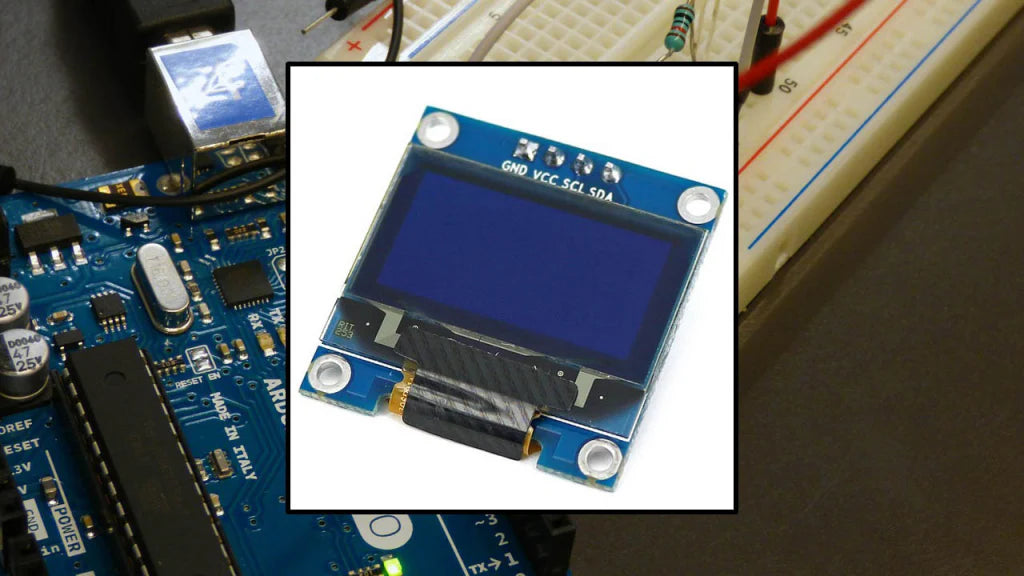
How To Install PMOLED Module Correctly
Installing a PMOLED module is mostly an electrostatic and connector problem, not a soldering one. Handle the panel by its edges with a grounded wrist strap, apply force to the frame or the FPC stiffener rather than the glass, mate the connector fully before any power is applied, and bring the rails up in the order the datasheet specifies. Most installation failures trace back to one of those four steps.
Handle the panel before it is powered
The glass in a PMOLED module is thin, and the organic stack behind it is damaged by current rather than by touch. ESD is the realistic risk: a discharge too small to feel can puncture the gate insulator of a row driver, and the result is a dead line that appears days later. A grounded wrist strap and a conductive mat cost less than one replacement module.
Lift the module by the rigid frame or by the stiffener at the end of the FPC. Bending the tail at the point where it meets the glass puts stress on the anisotropic conductive film bond, which is a mechanical joint with very little tolerance for peel. Peeling the protective film should be done slowly and at a shallow angle, away from the seal, and not with a metal tool near the edge.
Keep the protective film on until the module is mounted. Dust that settles on the polariser before assembly is difficult to remove without touching the surface, and the film is the only cheap protection available.
Know which connector you have
Three constructions are common. A ZIF connector on the host board takes the module's FPC tail and locks it with a latch. A hot-bar or soldered connection attaches the tail directly. A board-to-board connector mates the module to a matching header. Each fails differently.
With ZIF, the two failure modes are inserting the tail only partway, and closing the latch before the tail is seated. Both look assembled and both produce intermittent columns. With hot-bar, the failure is uneven heat: one end of the bond is under-cured and the other is over-pressed. With board-to-board, the risk is mechanical, because a connector that is not fully seated can pass a bench test and fail after the first drop.
A simple check after mating: tug the tail gently along its axis. If it moves, the latch is not engaged.
Follow the power-up sequence
PMOLED modules have more than one supply. The controller logic runs from a low voltage rail, and the panel itself needs a higher voltage that many modules generate on board with a charge pump. Where the datasheet defines an order, the order exists because reversing it forward-biases a junction that should be off.
The sequence that appears most often is: logic supply, then the panel supply or charge-pump enable, then reset released after the specified delay, then initialisation commands. Do not hot-plug a module on a live bus, and do not leave a supply connected while the logic rail is off. Both are common on a bench and both are capable of destroying a module that was working a minute earlier.
Decoupling belongs close to the panel, not only at the regulator. A charge pump switching at high frequency with a long supply path produces a supply that looks correct on a meter and dips at every refresh on a scope.
Match the interface the module expects
Most small PMOLED modules offer more than one interface, selected by strap pins or by a resistor option on the back of the board. A module strapped for SPI will not answer on I2C no matter what address the host scans, and the symptom — a completely silent display — is easily mistaken for a dead panel.
Read the silkscreen and the datasheet's interface table before writing code. Four-wire SPI, three-wire SPI, I2C and parallel 8080 or 6800 modes are all common on the same controller family, and the pin count on the tail tells you which one the module was built for. The PMOLED module range lists the interface alongside each part, which is quicker than deducing it from the tail.
Initialise in the documented order
Controller initialisation is a fixed script, and improvising it is the second most common cause of a blank display. The usual order is reset pulse, display off, clock and multiplex settings, charge pump enable, contrast or brightness, pre-charge period, then display on. A delay after enabling the charge pump is normally specified, and skipping it leaves the panel supply still rising when the first frame is written.
Brightness in a PMOLED is set by drive current, not by a backlight, so the contrast register is a current control. Setting it to maximum to make a dim panel brighter accelerates ageing across the whole display. If the panel looks dim at a normal setting, look for a supply problem before turning the register up. Modules that render graphics rather than characters carry more of this burden in firmware; the graphic OLED range is where a frame buffer and its RAM cost become part of the installation plan.
Mount it without loading the glass
A PMOLED is usually held by a bezel or a foam gasket, and the pressure path matters. The gasket should bear on the frame or on the area outside the seal, not on the active area, because a sustained point load changes the cell gap and shows as a permanent blotch.
Leave clearance in the bezel window for the module's own tolerance plus the adhesive thickness. Modules bonded with double-sided tape on the frame rather than the glass survive thermal cycling far better, since the glass and the housing expand at different rates.
Check current before checking the picture
Measuring supply current at first power-up catches most assembly faults before they become expensive. A module drawing noticeably more than its datasheet figure usually has a shorted tail or a reversed supply; one drawing far less is not initialising.
Then check the picture with patterns rather than a demo screen. A full-white field exposes dim rows and columns. A full-black field exposes pixels that stay lit. A fine checkerboard exposes column driver bonding, where a partially bonded tail shows as alternating light and dark vertical bands.
Uniformity is worth measuring if you intend to compare modules or batches. ISO 9241-307 sets out analysis and compliance test methods for electronic visual displays and refers to the measurement procedures of ISO 9241-305, which gives a defined basis for luminance and uniformity figures.[1]

Faults and what they usually mean
| Symptom | Usual cause | Where to look |
|---|---|---|
| Nothing at all, no current draw | No logic supply or held in reset | Rail voltage, then reset line |
| Silent on the bus | Wrong interface strap | Silkscreen and datasheet interface table |
| Very dim image | Charge pump not enabled | Initialisation sequence |
| One dark row or column | Bond defect at that driver | Tail seating, then bond inspection |
| Alternating vertical bands | Partially inserted tail | Re-seat and close the latch fully |
| Works, then fails after minutes | Overheating or overcurrent | Supply current against datasheet |
Reduce the risk of image sticking
Organic emitters age in proportion to the current that passes through them, so a static bright element fades relative to its neighbours. The practical mitigations are to keep average brightness modest, to avoid a fixed layout with a large white block, and to blank the display when the product is idle.
Where the interface allows it, shifting the image by a pixel every few minutes spreads the wear. It is a small change in firmware and it extends the useful life of a panel that would otherwise show a ghost of its own menu.
A PMOLED install succeeds or fails on four things: static control, a fully seated connector, a supply sequence taken from the datasheet, and an initialisation script that is not improvised. Check current first, then patterns, and most faults will identify themselves before a module is declared faulty.
References
- ISO 9241-307:2008 — Ergonomics of human-system interaction — Part 307: Analysis and compliance test methods for electronic visual displays. International Organization for Standardization. https://www.iso.org/standard/40102.html
En lire plus
NexPCB supports XR displays by delivering tailored PCB solutions, including 12-layer HDI boards with ±25μm micro-via precision to fit compact headset.
To enhance TFT LCD module brightness, tweak the backlight: raise LED current slightly or upgrade to brighter LEDs (e.g., 200nit panels to 300nit) , adjust.
Laisser un commentaire
Ce site est protégé par hCaptcha, et la Politique de confidentialité et les Conditions de service de hCaptcha s’appliquent.