


Industrial TFT LCD vs OLED Module Comparison | Control Panels, Instruments, HMI Devices
In industrial control panels, instruments, HMI devices, portable testing equipment, and smart terminals, both TFT LCD and OLED are common display options. Neither technology is universally better. The correct choice should be based on the operating environment, display content, brightness requirement, power budget, lifetime target, interface compatibility, mechanical space, and mass-production supply plan.
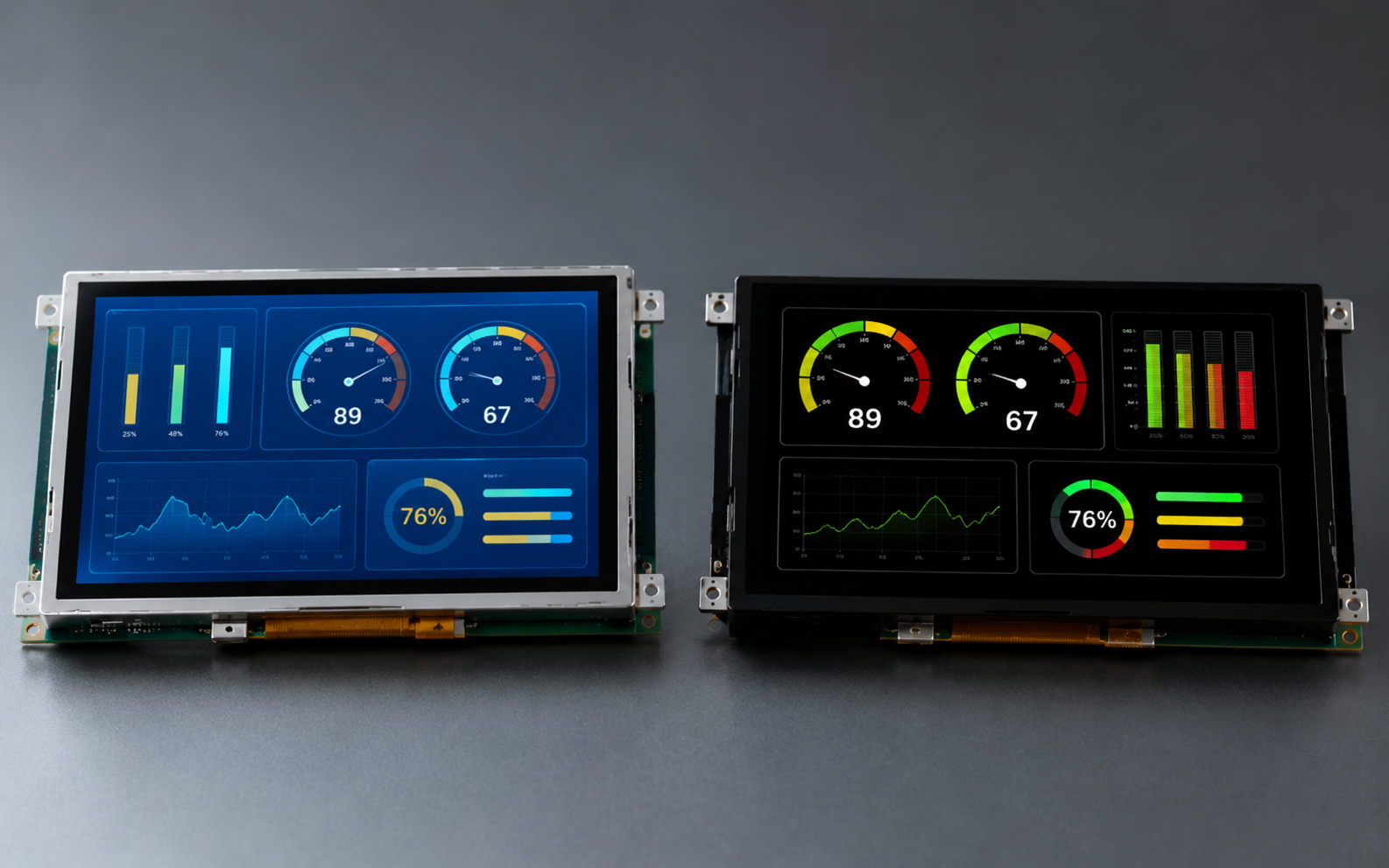
TFT LCD uses a backlight and liquid crystal layer to produce images. It is suitable for projects that require larger display sizes, stable always-on operation, mature supply chains, and multiple interface options. OLED is a self-emissive display technology. Each pixel can emit light independently, making it suitable for high contrast, dark-themed interfaces, thin structures, fast response, and compact high-quality displays.
DisplayModule’s public product lines include TFT LCD, IPS, Graphic OLED, Character OLED, AMOLED, Micro OLED, and other standard display modules. The company also supports sample evaluation, bulk procurement, custom display development, and driver-board design. This article compares TFT LCD and OLED from an engineering selection perspective, helping product managers, hardware engineers, and procurement teams make more reliable decisions during the early project stage.

Display Comparison
TFT Features
TFT LCD stands for Thin Film Transistor Liquid Crystal Display. It is an active-matrix LCD technology. Each pixel is controlled by a thin-film transistor, the liquid crystal layer modulates light, the LED backlight provides the light source, and the color filter forms RGB colors. Since the light source comes from the backlight, the power consumption of a TFT LCD is mainly related to backlight brightness and is less dependent on image content.
In industrial and instrumentation applications, the main advantages of TFT LCD are broad size coverage, multiple interface options, mature supply, stable always-on display performance, and the ability to improve readability through backlight design, cover glass, optical bonding, AG/AR surface treatment, and other optical structures. Public DisplayModule TFT product examples include 1.28-inch 240×240, 1.32-inch 360×360, 2.4-inch 240×320, 2.6-inch 320×240, 2.1-inch 1600×1600 high-PPI, and 3.4-inch 800×800 displays. Interface options include SPI, MCU, RGB, MIPI DSI, and others.
TFT LCD is especially suitable for equipment that needs to continuously display text, menus, charts, dashboards, control interfaces, and industrial status information. For mains-powered devices, automotive controls, industrial HMI, indoor panels, and semi-outdoor equipment, TFT LCD is often the safer starting point.
| Item | TFT LCD Engineering Features | Selection Notes |
|---|---|---|
| Display principle | Liquid crystal modulates light; LED backlight provides the light source | Backlight brightness, uniformity, and lifetime should be evaluated separately |
| Brightness control | Brightness is controlled through backlight current or PWM dimming | Higher brightness increases power consumption, heat, and backlight degradation risk |
| Size range | Used from small control panels to medium and large HMI devices | Specific sizes and resolutions should follow the product page and datasheet |
| Interface type | Common options include SPI, MCU, RGB, LVDS, MIPI DSI, and others | Confirm host interface support, voltage, timing, and bandwidth |
| Long-term display | Suitable for menus, dashboards, fixed icons, and always-on UI | Backlight lifetime, temperature, and pixel-defect standards still need evaluation |
OLED Features
OLED stands for Organic Light Emitting Diode. It is a display technology based on organic light-emitting materials. OLED does not require a backlight. Each pixel can emit light or turn off independently, giving OLED clear advantages in black-level performance, high-contrast interfaces, dark-environment display, and compact high-detail UI.
OLED can include Graphic OLED, Character OLED, PMOLED, AMOLED, Micro OLED, and other types. DisplayModule’s public OLED pages include Character OLED, Graphic OLED, AMOLED, and Micro OLED product categories. Public Graphic OLED examples include 0.42-inch 72×40, 0.91-inch 128×32, 0.96-inch 128×64, 1.5-inch 128×128, and 1.92-inch 128×160 displays. Public AMOLED examples include 1.2-inch 390×390, 1.39-inch 454×454, 1.78-inch 368×448, 2.4-inch 450×600, and 2.69-inch 800×600 models.
The main advantages of OLED are high contrast, excellent black levels, fast response, wide viewing angle, and the ability to support thinner mechanical structures. However, OLED brightness, lifetime, and image-retention risk are closely related to materials, display content, brightness setting, temperature, duty cycle, and driving strategy. For long-term fixed images, white-background always-on interfaces, or high-brightness outdoor display, lifetime and image-retention risk must be carefully evaluated.
| Item | OLED Engineering Features | Selection Notes |
|---|---|---|
| Display principle | Self-emissive pixels; no backlight required | Power consumption is strongly related to image content and brightness |
| Black performance | Black pixels can be turned off, providing strong black levels and contrast | Suitable for dark UI, status displays, and close-range viewing |
| Structural thickness | No backlight layer, supporting thinner mechanical designs | Cover glass, touch layer, FPC, and structural support still need consideration |
| Response speed | Fast response, suitable for dynamic graphics and small animations | Driver IC, interface bandwidth, and refresh method must still be confirmed |
| Lifetime risk | Brightness degradation and image retention require attention | Avoid long-term high-brightness fixed graphics and white-background always-on UI |
Suitable Applications
The suitable applications of TFT LCD and OLED mainly depend on the device environment, display content, and operating duration. Industrial projects should not select a display only by asking “which one looks better.” Real operating conditions, reading distance, power supply method, thermal design, maintenance cycle, and production stability should all be considered.
| Application Scenario | When TFT LCD Is More Suitable | When OLED Is More Suitable |
|---|---|---|
| Industrial HMI | Large display size, always-on interface, menus, and charts | Small status screen, dark theme, premium visual appearance |
| Portable instruments | Color charts, higher brightness, or long screen-on time required | Battery-powered device, dark UI, small amount of key data |
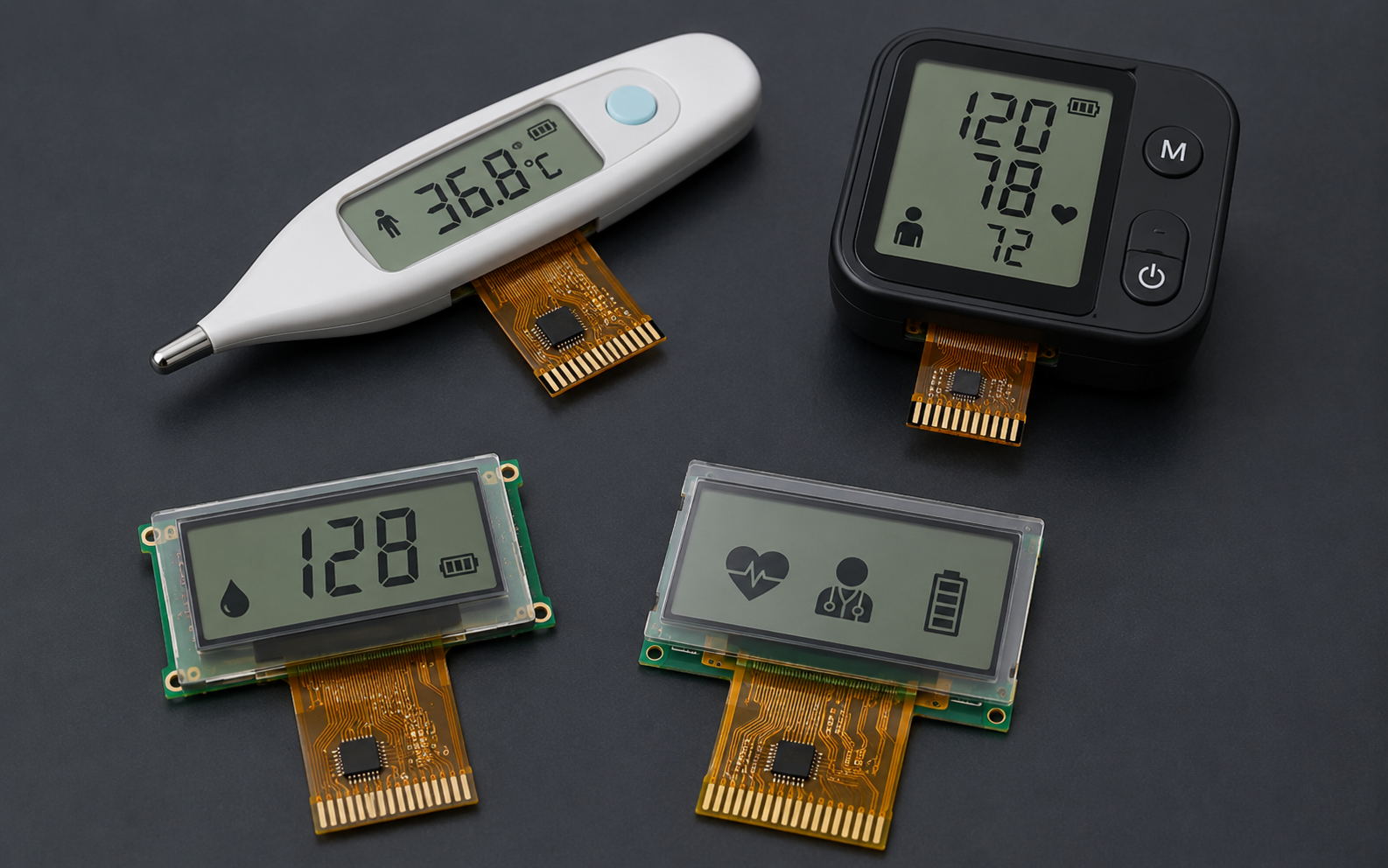
| Medical devices | Long display duration, stable readings, fixed interface content | Small screen for close viewing and high-contrast status alerts |
| Outdoor or semi-outdoor equipment | High-brightness backlight, optical bonding, and anti-reflection design required | Only suitable for low-brightness or short-duration display scenarios |
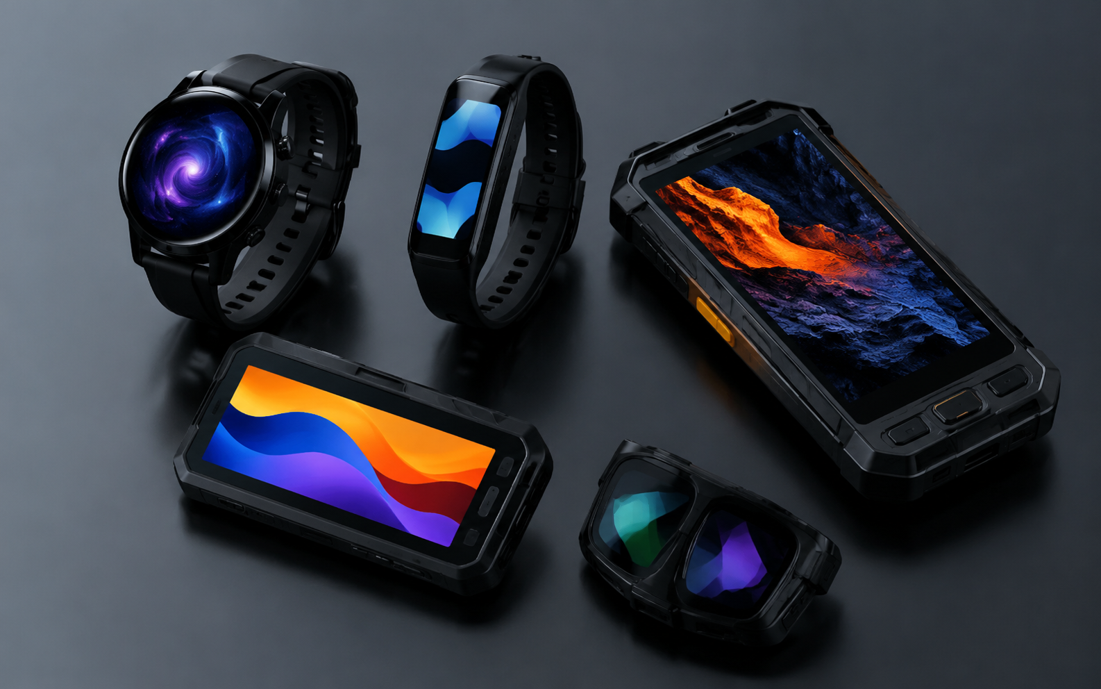
| Wearables and compact terminals | Cost-sensitive projects, simple UI, low refresh requirements | Thin structure, round display, high contrast, and low-duty-cycle display |
For industrial projects, the display technology choice should be discussed as part of the whole-device requirement review, not as a separate screen-parameter comparison. IP rating, drop resistance, EMC, ESD, cleaning-agent resistance, medical regulations, and automotive certification are usually device-level requirements and cannot be replaced directly by display-module specifications.
Performance Considerations
Brightness and Readability
Brightness is an important display-selection parameter, but it is not the only one. Readability in industrial equipment also depends on contrast, cover-glass reflectance, optical bonding, AG/AR treatment, viewing angle, font size, background color, ambient light, and user reading distance. Stating that a certain cd/m² value is suitable for outdoor use can be misleading because different optical structures and cover glasses can significantly affect final readability.
TFT LCD relies on a backlight and can improve brightness through LED backlight design, current control, and optical films. For strong-light or semi-outdoor environments, high-brightness TFT, low-reflection cover glass, optical bonding, and high-contrast UI should usually be evaluated together. OLED performs better in dark environments and dark-themed interfaces, but sustained high brightness increases power consumption, heat, and brightness-degradation risk.
| Use Environment | TFT LCD Recommendation | OLED Recommendation | Validation Focus |
|---|---|---|---|
| Indoor office or equipment panel | Standard-brightness TFT is usually sufficient | Suitable for dark UI and high-contrast status display | Font size, viewing angle, backlight uniformity, minimum brightness |
| Workshop, warehouse, semi-outdoor | Evaluate higher brightness and anti-reflection structure first | Evaluate contrast and brightness margin under ambient light | Actual cover glass, ambient light, heat, and power consumption |
| Strong outdoor light | Prioritize high-brightness TFT, optical bonding, and low-reflection cover glass | Do not rely only on high-brightness OLED to solve sunlight readability | Sunlight simulation, thermal test, long-term brightness degradation |
| Night or dark room | Confirm low-brightness dimming and backlight leakage | Strong advantages in black level, contrast, and dark UI | Minimum brightness, flicker, and visual comfort |
LCD optical testing can refer to the IEC 61747 series for liquid crystal display module measurement methods. OLED electro-optical parameter testing can refer to IEC 62341-6-1. If a display module adds touch, cover glass, or optical bonding, brightness, contrast, color, reflection, and readability should be retested using the final stack structure.
Power Consumption Differences
TFT LCD and OLED have different power-consumption behavior. TFT LCD power is mainly consumed by the backlight LEDs. Therefore, under the same brightness setting, power consumption usually does not vary greatly between white screens, black screens, and normal menu screens. OLED power consumption changes with the proportion of lit pixels, color, brightness, and refresh strategy. A black or low-duty-cycle image consumes less power, while a full-white or large-area high-brightness image consumes more power.
For this reason, it is not accurate to simply say “OLED is always more power efficient than TFT” or “TFT always consumes more power.” For dark UI, standby status, and small amounts of displayed data, OLED may be more efficient. For white-background always-on interfaces, maps, charts, video, or high-brightness interfaces, OLED power consumption may approach or even exceed that of a similar-size TFT.
| Test Scene | TFT LCD Power Behavior | OLED Power Behavior | Engineering Recommendation |
|---|---|---|---|
| Black screen | Backlight still consumes power | Few pixels are lit, so power consumption is lower | OLED is suitable for dark standby interfaces |
| White screen | Mainly determined by backlight setting | Large pixel area is lit, so power consumption is higher | Use OLED carefully for white-background always-on UI |
| Static text | Power is mainly determined by backlight | Depends on text area, color, and brightness | Test with the actual UI, not only datasheet typical values |
| Video or dynamic graphics | Backlight remains stable; host and interface power increase | Changes continuously with average image brightness | Record average power, peak power, and temperature rise |
| Long-term always-on display | Evaluate backlight lifetime and thermal design | Evaluate brightness degradation and image retention | Build lifetime and power budgets based on real duty cycle |
A reliable power test should include at least black screen, white screen, typical UI, maximum brightness, minimum brightness, standby mode, wake-up process, and continuous-operation temperature rise. The test record should include supply voltage, backlight current, OLED brightness setting, refresh rate, ambient temperature, host status, and firmware version.
Lifetime and Reliability
Lifetime is one of the most easily overlooked factors in industrial display selection. TFT LCD lifetime is usually related to LED backlight degradation, liquid crystal material, polarizer, temperature, and driving conditions. OLED lifetime is closely related to organic material degradation, brightness, temperature, display content, duty cycle, and driving method.
For TFT LCD, pay attention to the definition of backlight lifetime, such as L70 or L50 conditions, test temperature, driving current, and brightness-degradation curve. For OLED, pay attention to brightness degradation, color degradation, fixed-pattern image retention, local-area aging, and high-brightness operating time. IEC 62341-5-3 can be used as a reference for OLED image-sticking and lifetime measurement methods.
| Reliability Item | TFT LCD Focus | OLED Focus |
|---|---|---|
| Brightness degradation | Backlight LEDs degrade over time | Light-emitting materials degrade with brightness and time |
| Image retention | Usually lower risk, but abnormal image retention should still be evaluated | Fixed high-brightness icons and white-background interfaces have higher risk |
| High-temperature operation | Affects liquid-crystal response, backlight lifetime, and polarizer | May accelerate material degradation and brightness loss |
| Low-temperature operation | Liquid-crystal response may become slower | Confirm low-temperature startup, brightness, and driving stability |
| Pixel defects | Accept according to agreed pixel-defect class | Also define bright, dark, and sub-pixel defect rules |
Public articles should not promise absolute specifications such as “no bright dots, no dark dots, and permanent freedom from image retention.” Pixel defects should be accepted according to ISO 9241-307 or a customer quality agreement, including the defect class, test pattern, viewing distance, ambient light, and judgment method. Before mass production, appearance standards, pixel defects, brightness range, color tolerance, and failure-analysis process should be written into the quality documents.
Selection Guide
Device Requirements
Display-module selection should start from device requirements, rather than directly choosing a model from the display catalog. It is recommended to clarify the following questions at the early project stage:
- Use environment: indoor, semi-outdoor, outdoor, workshop, medical environment, or low-temperature environment.
- Display content: fixed menu, instrument readings, dynamic charts, video, icons, alarm status, or standby interface.
- Operating duration: intermittent screen-on, several hours per day, 24/7 continuous operation, or only lighting up during alarms.
- Power supply: coin cell, lithium battery, USB, mains power, automotive supply, or industrial power supply.
- Mechanical space: window size, thickness limit, FPC direction, connector position, cover glass, and touch layer.
- Reliability requirements: temperature, humidity, drop, vibration, ESD, EMC, cleaning agents, and long-term supply.
- Mass-production conditions: target annual volume, sample stage, BOM target, certification cycle, lead time, and lifecycle.
If the device needs a larger display, fixed menus, white-background UI, or long-term always-on operation, TFT LCD usually makes it easier to control risk. If the device needs a compact display, dark UI, thin structure, low-duty-cycle display, or high-contrast status indication, OLED should be evaluated first.
Interface Compatibility
Interface compatibility directly affects host-controller selection, PCB routing, driver development, refresh speed, EMI, and BOM cost. Both TFT LCD and OLED may use SPI, MCU, RGB, MIPI DSI, and other interfaces, but common interface choices differ by display size and technology. The datasheet of the exact model must be confirmed instead of judging only by display technology.
| Interface Type | Common Display Applications | Advantages | Notes |
|---|---|---|---|
| SPI / QSPI | Small TFT, Graphic OLED, status screens | Low pin count, simple wiring, broad MCU support | High resolution or video refresh may be limited |
| I²C | Character OLED, small monochrome OLED, touch controllers | Simple bus, can be shared with other low-speed devices | Not suitable for large image-data refresh |
| 8080 / 6800 MCU | Small and medium TFT, graphic LCD, some OLED modules | Parallel data transfer and clear driving logic | Uses more I/O pins and makes PCB routing more complex |
| RGB parallel | Medium-size TFT HMI and industrial panels | Suitable for continuous color image refresh | Requires more data lines and stable clock signals |
| LVDS | Larger TFT displays and longer board-to-board connections | High speed and relatively good noise immunity | Requires matching host, cable, and panel specifications |
| MIPI DSI | High-resolution TFT, AMOLED, smart-terminal displays | High speed, fewer lines, suitable for high pixel density | Debugging must consider lane count, timing, initialization, and compatibility |
During interface review, confirm whether the host supports the required interface, whether the I/O voltage matches, whether level shifting is needed, whether driver code is available, whether a bridge IC is required, whether the FPC pins are easy to route, whether the touch interface uses additional I²C or SPI resources, and whether screen initialization, sleep, and wake-up timing can be controlled reliably by firmware.
Cost Analysis
Display cost should not be evaluated only by module unit price. For industrial equipment, it is better to evaluate total cost of ownership, including module price, driving circuit, backlight circuit, touch, cover glass, mechanical parts, development and debugging, certification, power consumption, thermal design, repair, spare parts, and lifecycle.
| Cost Item | TFT LCD Focus | OLED Focus |
|---|---|---|
| Module cost | Mature sizes often offer more choices and stable supply | Advantages in small-size and high-contrast applications, but some sizes may cost more |
| Driver circuit | Requires backlight driver, PWM dimming, and power design | Confirm OLED power, driver IC, and initialization requirements |
| Mechanical cost | Backlight and module thickness may increase structural space | Thin design is an advantage, but cover glass and protection structure still matter |
| Power cost | Always-on backlight affects battery and thermal design | Dark UI can save power; high-brightness white UI may consume more |
| Maintenance cost | Focus on backlight degradation and field replacement strategy | Focus on image retention, brightness degradation, and UI anti-aging strategy |
| Supply risk | Confirm lifecycle, alternative models, and bulk lead time | Confirm panel supply, driver IC, and long-term availability |
If a product needs years of continuous operation, fixed UI, and stable supply, TFT LCD is often easier to control in terms of total cost. If a product emphasizes thin appearance, low-duty-cycle display, dark theme, and compact high-contrast visuals, OLED may bring more value in user experience and system power consumption.
Sample Validation
Whether choosing TFT LCD or OLED, sample validation should be performed in the real device environment. Lighting up a screen on a development board does not prove that the display solution is suitable for mass production. Final validation should include the actual enclosure, real cover glass, touch layer, final PCB, production firmware, power design, connector, FPC bending path, and typical UI content.
| Validation Item | Test Content | Recommended Record |
|---|---|---|
| Mechanical fit | Outline size, active area, viewing area, thickness, FPC direction, connector position | Assembly photos, 2D drawings, structural interference records |
| Electrical bring-up | Power sequence, reset, initialization, interface communication, sleep and wake-up | Oscilloscope screenshots, firmware version, initialization code |
| Optical performance | Brightness, contrast, viewing angle, color, uniformity, reflection | Test conditions, instrument model, ambient light, cover-glass condition |
| Power and temperature rise | Typical UI, white screen, black screen, maximum brightness, standby, wake-up | Current curve, temperature record, supply condition |
| Reliability | High/low temperature, damp heat, aging, ESD, FPC bending, backlight, or image retention | Test duration, judgment standard, failure photos |
| Appearance quality | Bright dots, dark dots, scratches, stains, light leakage, mura, foreign material | Inspection conditions, pixel-defect class, sample number |
Optical measurement of LCD modules can refer to IEC 61747 methods. OLED electro-optical parameters can refer to IEC 62341-6-1. OLED image retention and lifetime can refer to IEC 62341-5-3. Pixel defects and appearance standards should be clearly defined in the purchasing specification or quality agreement, not judged temporarily after mass production.
Mass Production Recommendations
Before entering mass production, the customer should lock the display model, datasheet version, mechanical drawing, interface definition, initialization code, backlight parameters, touch parameters, cover-glass structure, packaging method, and acceptance standard. Any change involving the driver IC, FPC, interface, backlight, polarizer, touch, cover glass, or supply materials should trigger a new sample evaluation and reliability-risk review.
DisplayModule’s public information shows that its standard display modules can be used for sample evaluation and bulk procurement, and that it supports FPC shape modification, cover-glass customization, small-batch prototypes, and mass-production coordination. Specific MOQ, bulk price, and lead time vary by model, quantity, customization scope, and material availability, and should not be written as fixed commitments in a general article.
When submitting an inquiry or selection request, it is recommended to provide the following information:
- Target application: industrial HMI, medical device, instrument, consumer electronics, automotive, or wearable device.
- Display content: text, icons, charts, video, dark UI, white-background UI, or always-on status bar.
- Size and resolution: target screen size, active display area, pixel density, and outline limits.
- Interface requirement: SPI, I²C, MCU, RGB, LVDS, MIPI DSI, or other interfaces.
- Host information: MCU/SoC model, I/O voltage, available pins, display memory, and system bandwidth.
- Optical requirements: brightness, viewing angle, cover glass, AG/AR, optical bonding, and outdoor readability.
- Power requirements: battery capacity, operating duration, backlight strategy, sleep and wake-up method.
- Reliability requirements: temperature, humidity, ESD, lifetime, image retention, pixel defects, and packaging.
- Production plan: sample quantity, pilot-run timing, annual volume, lifecycle, and alternative-solution requirements.
The final selection can follow a simple principle: if the project requires a larger size, fixed interface, long-term always-on operation, and stable supply, evaluate TFT LCD first. If the project requires a thin structure, high contrast, dark UI, short-duration display, or compact premium visual performance, evaluate OLED first. Whichever technology is selected, it should enter mass production only after sample testing, real-UI power measurement, optical validation, and quality-standard confirmation.
En lire plus
DisplayModule supplies standard AMOLED display modules and supports bulk procurement, custom display integration, FPC modification, cover glass customization, driver-board development, and engineer...
COG LCD display modules are widely used in compact products that need low power consumption, stable readability, simple MCU integration, and a thin mechanical structure. Typical applications includ...
Laisser un commentaire
Ce site est protégé par hCaptcha, et la Politique de confidentialité et les Conditions de service de hCaptcha s’appliquent.