


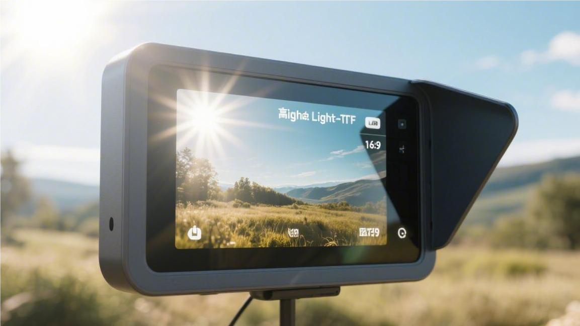
Sunlight Readable TFT Displays | Nits Brightness, Contrast & Anti-Glare
Sunlight readable TFT displays must feature a high brightness of over 1000 nits and a contrast ratio of 800:1.
Operationally, an anti-glare (AG) coating needs to be applied to the screen surface combined with an optical bonding process to reduce the screen's light reflectance to below 1%.
Nits Brightness
Faced with direct sunlight with an ambient illuminance of 80,000 Lux, the image signal of a conventional 300 Nits screen will be completely overwhelmed by the ambient light.
To read data normally under such lighting conditions, the output of the panel's backlight module needs to reach 1000 Nits.
In specific environments, such as offshore drilling platforms in the North Sea or aviation dashboards, hardware specifications are usually set between 1500 and 2500 Nits to counteract optical interference caused by strong light and specular reflections from water surfaces or clouds.
Illuminance Matching Standards
In Florida at noon during summer, the ambient illuminance can reach 107,639 Lux. At this time, the intensity of reflected light on the glass surface becomes the main variable interfering with the image signal.
Conventional 1.1mm thick soda-lime glass has a natural reflectance of approximately 4.5%. If the ambient light is 100,000 Lux, the brightness of the reflected light generated on the screen surface will reach 4,500 Lux.
For operators to see the screen clearly, the luminous intensity of the display must be much higher than the interference intensity of the reflected light. The industrial display field generally requires a Contrast Ratio of 5:1 or higher to ensure the edges of text and graphics are clearly distinguishable.
Below are typical quantitative indicators of illuminance and brightness requirements for different geographical locations and application scenarios:
| Deployment Area | Max Ambient Illuminance (Lux) | Reflectance Control (%) | Recommended Screen Brightness (Nits) | Visual Contrast Effect |
|---|---|---|---|---|
| Nordic Cloudy (Oslo) | 20,000 | 4.0% (Air Bonding) | 500 - 600 | Good Readability |
| California Coast | 85,000 | 1.2% (AR Coating) | 1,000 - 1,200 | Clear under Strong Light |
| Sahara Desert / High Altitude | 120,000 | 0.5% (Optical Bonding + AR) | 1,500 - 2,000 | Ultra-High Fidelity |
| Antarctic Research Station (Snow) | 90,000 | 0.2% (Custom AG/AR) | 1,800 | Eliminates Snow-Blinding Reflections |
The calculation formula can be simplified as: Screen Brightness / (Screen Brightness × Surface Reflectance + Ambient Illuminance / π × Reflectance) + 1. In an 80,000 Lux environment, to maintain a minimum readability of 3:1, a screen with 5% reflectance must provide at least 1,200 Nits.
When the ambient illuminance climbs from 30,000 Lux to 100,000 Lux, the human eye's perception of brightness does not increase linearly. On solar power plant maintenance terminals in Nevada, simply increasing the Nits value is not enough to solve the problem; the backlight system's color temperature needs to be locked between 6500K and 7500K.
In high-latitude regions like Alaska, although the sun's elevation angle is low, the albedo of the surface ice and snow is as high as 0.8 to 0.9. The bottom of the screen will also be exposed to strong secondary reflected light, making the tight coordination between the sealed light-shielding design of the device's bottom bezel and screen brightness crucial.
-
1500 Nits Threshold: For unsheltered gas pump displays, increasing the brightness to 1500 Nits can cover 95% of extreme global sunlight periods.
-
0.5% Reflectance: Through the vacuum magnetron sputtering process, the 4% glass reflectance is reduced to 0.5%, yielding a visual improvement equivalent to doubling the brightness.
-
10-bit PWM Dimming: To adapt to the massive span from 5 Lux deep in the night to 100,000 Lux at noon, the driver circuit must support 1024 levels of brightness adjustment stepping.
In automated ticket machines in Arizona, the Ambient Light Sensor (ALS) samples the ambient Lux value at a frequency of 10 times per second. The control circuit adjusts the LED drive current based on a preset logarithmic curve, keeping the Nits output consistently within 1.2 to 1.5 times the ambient brightness.
Without this dynamic matching, if the backlight system remains at a full load of 2000 Nits for a long time, the LED bead Junction Temperature will quickly exceed 125°C. This would result in screen brightness degradation of over 30% within 24 months, failing to maintain long-term outdoor visibility standards.
In the trade-off between Reflection and Luminance, Optical Bonding eliminates the air gap between the LCD panel and the protective glass by filling it with OCA adhesive with a refractive index of 1.49. This eliminates 90% of the internal reflection paths, making an 800 Nits screen perform better in sunlight than a 1200 Nits air-bonded screen.
For maritime navigation equipment, salt spray and high humidity will alter the optical characteristics of the glass surface. Engineers will select a hydrophobic coating with a 110° water contact angle. This prevents rainwater from forming scattering light spots, ensuring that on a sea surface with 50,000 Lux illuminance, symbols at the screen edges still maintain a high dynamic contrast ratio of 15:1.
The fine-tuning logic for Nits requirements across different materials is as follows:
-
Standard Tempered Glass: Reflectance is about 4.2%, making 1000 Nits the basic threshold.
-
AG (Anti-Glare) Etched Surface: Scattered light reduces specular interference but will lose 3% to 5% of the original brightness.
-
AR (Anti-Reflective) Multi-layer Coating: Allows over 98% of backlight penetration, which is standard for ultra-high brightness screens over 2000 Nits.
-
PET Polarizer: For users wearing polarized sunglasses, a Quarter-wave plate must be added to the outermost layer to prevent the screen from going black.
In outdoor charging station tests in German industrial parks, data shows that when illuminance exceeds 60,000 Lux, the human eye's visual focus will fatigue due to high contrast differences. Therefore, the Uniformity of high-brightness screens must be maintained above 80% to avoid excessively bright or dark local color patches.
The backlight lifespan (MTBF) must also be considered during selection. When outputting a full 1500 Nits, the working life of an LED is usually rated at 50,000 hours. If the device is located in Texas, where the actual operating ambient temperature is consistently above 40°C, its physical lifespan will shorten to about 60% of the original factory nominal value.
To offset this long-term degradation, a brightness compensation space of 200 to 300 Nits is reserved in the circuit design. When the sensor detects that the total LED operating time reaches 20,000 hours, the motherboard will automatically slightly increase the PWM duty cycle, forcibly maintaining the illuminance matching level set at the factory.
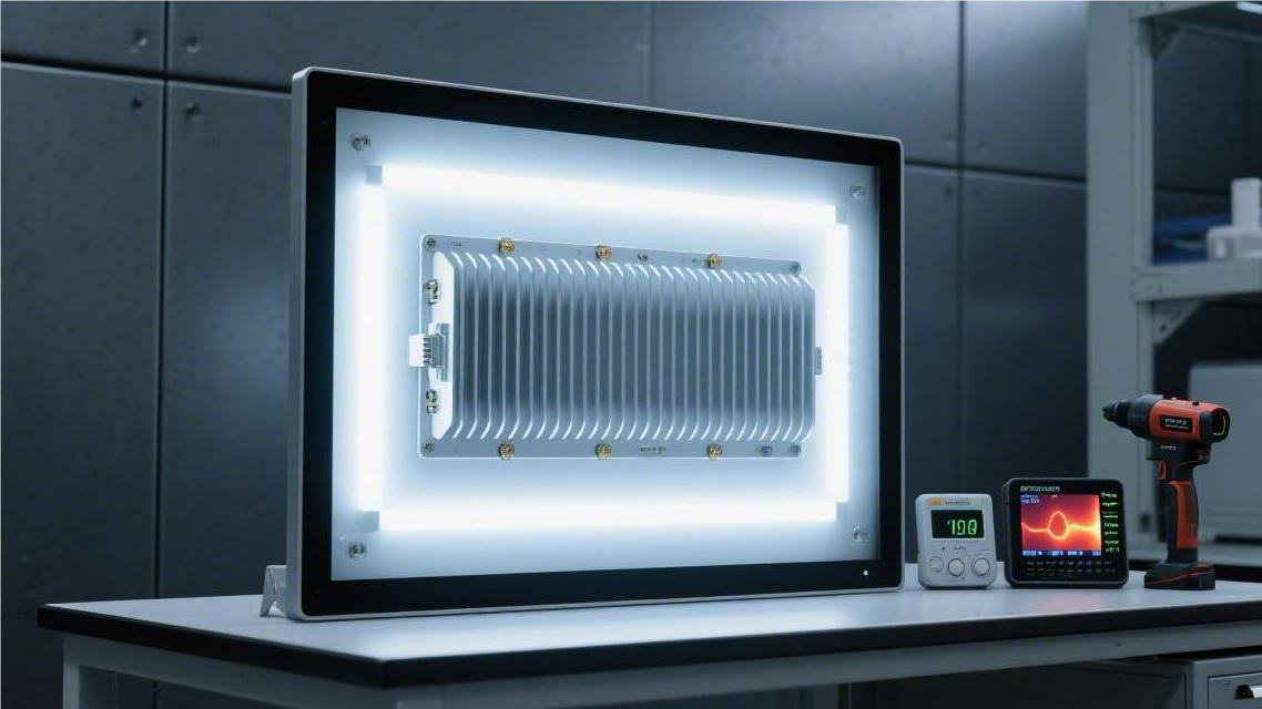
Power Consumption and Thermal Design
Elevating a TFT panel's brightness from the standard 300 Nits to 1500 Nits results in a non-linear increase in the backlight module's energy consumption. The Luminous Efficacy of white LED beads degrades when the current exceeds 60 mA. Engineers push the drive current to 120 mA or even 150 mA. Taking a 15-inch panel as an example, the power consumption climbs from 8 watts to 35 watts.
Of the 35 watts of electrical energy input into the backlight system, about 30% is converted into visible light, while the remaining 70% is transformed into heat. A 24.5-watt thermal load is concentrated on the backlight side bezel, which is less than 2mm thick. Every square centimeter of the aluminum frame must withstand a Heat Flux of 5 watts.
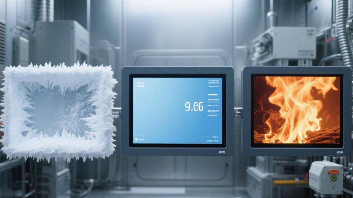
Different components have strict physical limits regarding temperature tolerance; exceeding these boundaries causes irreversible damage:
-
LED Junction Temperature (Tj): Exceeding 125°C causes the phosphor to carbonize.
-
Polarizer: Shrinkage and yellowing occur above 85°C.
-
Driver IC Chip: Leakage current multiplies at 105°C.
-
Backlight Light Guide Plate: Acrylic material warps at 90°C.
Ambient light radiation further drives up the temperature on the panel surface. At noon in summer in Texas, solar irradiance reaches 1000 watts per square meter. Anti-glare glass and liquid crystal layers absorb infrared rays, causing a 15-inch screen to absorb an additional 18 watts of environmental heat per hour. With internal and external heat sources combined, the screen surface temperature can breach 85°C within 45 minutes.
When conventional Nematic liquid crystal materials reach 75°C, the orderly arrangement of molecules is destroyed. The liquid crystal transitions into an Isotropic liquid state, losing its ability to deflect light. From a user's perspective, huge black patches appear on the screen, a phenomenon the industry calls "Solar Clearing".
Brightness Degradation Redundancy
According to the IES LM-80 test standard, industrial-grade high-brightness LED beads running continuously for 50,000 hours in a 55°C environment will trigger the L70 degradation node.
Upon reaching the L70 node, a panel that originally output 1500 Nits can only emit a maximum of 1050 Nits. For highway toll terminals in Texas, equipment is required to run 24/7 without downtime, amounting to 8,760 working hours a year.
Calculated at 8,760 hours of full-load energy consumption, after 5.7 years, the screen surface brightness would fall below the 1000 Nits outdoor visibility baseline. To combat the optical law of light decay, hardware engineers introduce a mandatory reservation mechanism on the circuit side.
The nominal Nits value on the purchasing specification sheet must be 25% to 40% higher than the project's actual illuminance demand. Assuming an ATM deployed in Nevada requires 1200 Nits to resist noon sunlight, the initial custom panel selection will usually be locked at 1600 Nits or a higher spec.
Physical redundancy is not simply adding more LED beads inside the backlight cavity; its foundation relies on dynamic suppression and long-cycle release of the underlying drive current.
During the first three years of device deployment, the Constant Current Source driver IC on the motherboard actively limits the power delivered to the backlight layer. The factory sets the full-load rated drive current of a single LED at 120 mA, but the control system only allocates 85 mA initially.
-
Duty Cycle Suppression: Locks the Pulse Width Modulation (PWM) duty cycle at 75%, making 1600 Nits hardware output only 1200 Nits.
-
Junction Temperature Control: Reducing the power supply by 35 mA quickly drops the surface operating temperature of the aluminum-based light bar by 12°C to 15°C.
-
Crystal Aging Delay: The lower junction temperature slows down the carbonization rate when the internal blue LED chip excites the yellow phosphor, extending the L70 lifespan from 50,000 hours to 75,000 hours.
The Ambient Light Sensor (ALS) and the internal clock chip of the Microcontroller Unit (MCU) build a closed-loop compensation link together. The motherboard records the cumulative lighting time of the backlight module.
When the cumulative running time crosses the 15,000-hour mark, LED luminous efficacy naturally drops by about 8%. The system will automatically modify the internal parameters of the backlight control register, fine-tuning the PWM duty cycle from the initial 75% up to 81%.
The compensation circuit uses a detection cycle of every 5,000 hours, gradually releasing the 400 Nits of brightness space sealed off in the early stages.
Stepped current compensation operations are invisible to the end user. Over an 8-year life cycle, the screen brightness of an outdoor parking meter in California at 12 noon consistently remains at the value of 1200 Nits.
If the 400 Nits redundancy was not planned at the beginning of the project, the LED panel would degrade to 850 Nits by the 4th year due to natural decay. Under the intense summer light of 80,000 Lux, the screen contrast would slip below 2:1, causing a massive amount of reading errors.
Redundancy calculations for polar environments utilize a different formula architecture. At oil and gas pipeline monitoring stations in Alaska, winter polar night temperatures often drop to -30°C. Although low temperatures significantly extend the luminous life of LEDs, they stretch the response time of liquid crystal molecules from 15 milliseconds to a massive 120 milliseconds.
-
Low-Temperature Heating Loss: A layer of 15-watt transparent ITO heating film must be attached to the back of the screen to heat the liquid crystal layer to above 0°C.
-
Optical Path Obstruction: The insertion of the heating film results in an optical transmittance loss of about 7% to 9%.
-
Baseline Upward Adjustment: While 1000 Nits could originally meet snow anti-reflection needs, to offset the optical obstruction caused by the heating film, the panel's initial procurement standard must be raised to 1200 Nits.
Brightness safety standards in the aerospace and marine sectors are even more stringent. The backlight architecture of the Primary Flight Display (PFD) in Boeing aircraft cockpits uses a dual-channel cross-power supply design. Behind a 15-inch panel, 480 LED beads are arranged, divided into two independent interlaced power circuits, A and B.
During daily flights, circuit A operates at 60% power to provide 1000 Nits, while circuit B is in a 5% power sleep standby state. If the driver chip of circuit A suffers a thermal breakdown, circuit B will instantly switch to 60% power within 50 milliseconds to take over illumination.
Aviation displays utilize 100% physical channel duplication to ensure that over a 15-year service period, any single-point component aging or damage will not trigger a sudden drop in overall machine Nits.
The Polarizer of industrial LCD modules also faces lifespan degradation. Eroded by the constant high-humidity air of over 85% in Florida, the transmittance of an iodine-based polarizer will drop from 42% to 38% within 5 years. Reserving a 300 Nits emission margin can completely mask the image darkening phenomenon caused by the yellowing of the polarizer.
Contrast
For a screen with a darkroom contrast of 1000:1, under direct sunlight of 10,000 Lux, the ACR usually drops below 2:1, making it unreadable.
Industrial standards for outdoor equipment in Europe and America require a minimum ACR of 5:1, with an ideal state being greater than 10:1.
By introducing the Optical Bonding process to eliminate the air layer between liquid crystals, internal light reflection can be reduced by 4.3%, boosting ambient contrast by 300% to 400%, thus ensuring black depth and text sharpness under strong light.
Outdoor Contrast
The contrast parameters marked by panel suppliers in specifications are usually measured by colorimeters in controlled laboratories with an ambient illuminance of 0 Lux. For instance, a typical 12.1-inch industrial-grade panel showing a full-white brightness of 1200 Nits and full-black brightness of 1.2 Nits is labeled with a static contrast ratio of 1000:1.
When this panel is exposed to the direct sunlight of a typical North American summer noon, the external ambient illuminance can easily exceed 85,000 Lux. Ambient light hitting the screen glass and polarizer surface will produce about 4.5% physical reflection. This reflection adds an equivalent brightness of about 3825 Lux on top of the original brightness.
The actual readability at this time is defined by the Ambient Contrast Ratio (ACR). Physical calculation superimposes the reflected light onto the light emitted by the display, turning the formula into (1200 + 340) / (1.2 + 340). Because the reflected brightness dominates, the calculation result is about 4.5:1. According to physiological visual research, when this value is below 3:1, the human eye cannot distinguish image edges.
Aviation instruments and industrial handheld terminals have clear, mandatory numerical requirements for outdoor readability. For equipment operated under intense sunlight, engineers usually pursue an ACR baseline higher than 5:1. If complex dynamic maps or high-resolution surveillance footage need to be displayed, this value should be maintained in the range of 10:1 to 15:1.
Contrast degradation under different brightness gradients is non-linear:
-
A 500 Nits display under 10,000 Lux has an ACR of about 2.1:1; visually, it appears severely washed out.
-
A 1000 Nits display under 10,000 Lux raises the ACR to 3.2:1, making it barely readable.
-
A 1500 Nits display combined with 4.5% reflectance hits an ACR of 4.3:1, meeting initial visibility requirements.
-
A 1000 Nits display combined with 1.5% reflectance allows the ACR to jump to 7.5:1, presenting a clear and readable state.
Simply increasing the brightness of the LED backlight module to counter reflected light is highly inefficient. Raising the backlight from 1000 Nits to 2000 Nits causes the module's power consumption to spike from 12W to over 28W. However, under the same reflective environment, the contrast only improves from 4.4:1 to 6.7:1, while bringing excessive heat accumulation.
An effective method is to reduce physical reflectance. Panels using AR (Anti-Reflective) coatings can push surface reflectance down from 4.5% to below 0.5%. Under 85,000 Lux sunlight, reflected light brightness plummets from 380 Nits to 38 Nits. This single modification can surge the ACR of a 1000 Nits panel from 4.4:1 to 26:1.
MIL-STD-3009 Aviation Standard: Specifies that Electronic Flight Instrument Systems (EFIS) must have a contrast greater than 3.0 in a 10,000 fL (foot-lamberts) environment.
SAE J1757-1 Automotive Standard: Specifies that in-vehicle displays under specific test fixtures must meet specific thresholds for high-light reflection contrast to ensure drivers recognize warning icons within 0.5 seconds.
The physical loss of contrast leads to the collapse of the Color Gamut. A panel with 72% NTSC color gamut in a pitch-black lab will have its effective color gamut shrink to less than 15% under direct sunlight because dark pixels are physically covered by reflected light. Colored icons will look like faded photos in a fog.
Improving the ACR value effectively locks in color saturation. When ACR reaches 10:1, the screen can restore about 50% of the original color gamut space. In automated agricultural machinery navigation or outdoor GPS devices, accurate color contrast can distinguish vegetation, roads, and water boundaries on a map, reducing operational errors caused by visual blurring.
The arrangement of liquid crystal molecules also affects the upper limit of outdoor contrast. Normally, the darkroom contrast of IPS (In-Plane Switching) panels is around 1000:1, while VA (Vertical Alignment) panels can reach 3000:1. But under the severe interference of 80,000 Lux light, since reflected light dominates the optical path, the outdoor ACR performance of both panels converges.
The Haze value of the screen surface has a secondary impact on contrast performance. To prevent specular glare, AG (Anti-Glare) glass is etched with micro-bump structures that scatter incident light in all directions. While this eliminates glaring reflections, the scattered light forms an even layer of white background noise, making black pixels look less deep.
In a maritime environment, reflected light from the sea surface is highly polarized. The interference model of ambient light changes from omnidirectional diffuse reflection to specific-angle polarized interference. If the angle of the internal polarizer of the TFT screen aligns with the axial direction of the environmental reflected light, the effective contrast of the screen will instantly drop below 1.5:1.
The solution to physical polarization interference is to introduce a Quarter-wave Plate (QWP). The compensator can convert the reflected linearly polarized light into circularly polarized light, which is then blocked by the display's outermost polarizer. After introducing this technology, marine radars can maintain an operational contrast above 7:1 even in environments with intense water surface reflection.
Here are optical parameter comparisons in typical application scenarios (based on 50,000 Lux standard sunlight):
-
Outdoor Bus Shelters: 1200 Nits, 4.0% reflectance, ACR is approx. 7.0:1, readable from a normal standing distance.
-
Gas Station Pumps: 1500 Nits, 4.5% reflectance, ACR is approx. 7.6:1, meets high-frequency outdoor operational needs.
-
Military Rugged Tablets: 800 Nits, 0.8% reflectance, ACR is approx. 21.0:1, suitable for high-detail map display.
-
Standard Laptops: 300 Nits, 5.0% reflectance, ACR is approx. 2.2:1, presents a black screen state in sunlight.
High contrast design also significantly improves touchscreen operation accuracy. In infrared or capacitive touch solutions, users need to clearly identify the boundaries of UI elements for precise tapping. Boosting the ACR from 3:1 to 8:1 shortens the user's visual confirmation time by 45%, effectively reducing queue waiting times at outdoor self-service terminals.
ISO 9241-307 Standard Recommendation: To guarantee comfort during prolonged reading, the contrast ratio of display devices in typical working environments should not be lower than 10:1 to prevent excessive strain on ocular focusing muscles.
Contrast gain data for different bonding processes:
-
Air Bonding: Internal air gap contributes about 4.3% reflectance; total reflectance is approx. 9%; under 50,000 Lux, ACR is only 3.6:1.
-
Optical Bonding: Eliminates air gap reflection; total reflectance drops to 0.5%-1.5%; under 50,000 Lux, ACR can reach 15:1 or above.
By precisely controlling the etching depth (Ra value) of the protective glass surface and the sputtering thickness of the AR coating layer, engineers can customize contrast curves according to customer needs. For outdoor audiovisual equipment demanding extreme black purity, top-tier AR glass with a reflectance below 0.2% is usually selected in exchange for excellent visual depth.
Optical Bonding
Traditional TFT screens have a 0.1mm to 0.5mm air gap between the protective glass and the liquid crystal layer. Due to the difference between the refractive index of air (1.0) and glass (1.5), light undergoes two physical reflections at the interface. Each reflection causes a luminous flux loss of about 4.2% to 4.5%, allowing strong external light to wash directly over the screen content.
Optical Bonding unifies the refractive indices of the glass, adhesive, and polarizer by filling the gap with transparent Optically Clear Adhesive (OCA) or Optically Clear Resin (OCR) with a refractive index of 1.49. This physical filling eliminates the internal air layer, driving the overall reflectance from a high of 8.5% down to between 0.2% and 1.5%.
When outdoor illuminance hits 10,000 Lux, the reflected brightness generated by an ordinary air-bonded screen is about 850 Nits. In contrast, a screen using optical bonding has a reflected brightness of only 150 Nits. The 700 Nits reduction in background interference significantly broadens the dynamic range, making dark details clearly visible in sunlight.
Tailored for different industrial scenarios, optical bonding materials exhibit differentiated physical characteristics:
-
Rigid OCA tape: Thickness ranges from 50um to 250um, suitable for automated assembly of smart wearables.
-
Liquid OCR resin: Fill thickness can reach 0.5mm to 2.0mm, compatible with curved screens with large uneven surfaces.
-
Anti-UV adhesive: For outdoor aging tests, it must pass over 1000 hours of QUV ultraviolet irradiation experiments.
-
High-transmittance materials: Transmittance in the visible light band (380nm-780nm) must be 99% or above.
-
Wide temperature tolerance: Operating temperature range covers -40°C to +85°C to prevent delamination under extreme hot-cold cycling.
| Physical Metrics | Air Bonding | Optical Bonding |
|---|---|---|
| Internal Reflectance | Approx. 4.3% | < 0.2% |
| Visible Light Transmittance | ~86% - 91% | > 98% |
| Impact Resistance Rating | Below IK06 | Elevated to IK08/IK10 |
| Moisture Resistance | Prone to internal condensation | Physically sealed, zero moisture intrusion |
| Heat Dissipation Efficiency | Air insulates, high thermal resistance | Gel conducts heat, efficiency up by >20% |
Hot air forms a thermal resistance layer in the 0.3mm gap, causing the panel center temperature to be 15°C higher than the ambient temperature. Optical bonding uses the thermal conductivity of solid media to rapidly transfer heat generated by the backlight to the front glass.
In terms of physical protection, the bonding layer acts as a pressure buffer. Upon enduring an external 10-Joule impact, the adhesive layer distributes the impact force evenly across the entire panel surface. This structural reinforcement allows ordinary 1.1mm thick tempered glass to meet the impact resistance standards required for marine-grade equipment, preventing the risk of flying glass shards.
Selecting the optical bonding process also requires considering repair rates and material waste. Liquid OCR dispensing has fluidity before curing, allowing it to compensate for surface flatness tolerances within 0.05mm of the panel. The curing process is triggered by 365nm wavelength UV light; shrinkage must be strictly controlled within 1.5% to avoid pressure-induced yellow spots on the screen body.
Outdoor handheld terminals frequently face salt spray corrosion and condensation risks. The optical bonding process completely seals the gap between the display screen and the touch layer via physical encapsulation. Even in tropical rainforests with 95% humidity or polar research equipment at minus 30°C, internal fogging that obstructs the view will not occur.
For high-altitude flight instruments, optical bonding effectively counters inter-layer expansion caused by air pressure changes. In low-pressure environments at an altitude of 30,000 feet, gases inside air-bonded screens physically expand, generating Newton's rings (interference fringes). The optically bonded structure eliminates the gas medium, ensuring geometric image consistency under pressure variations.
The specific performance gains of optical bonding in system design are as follows:
-
Power saving: For the same visual clarity, LED drive current can be reduced by 30%, extending battery life by 2-3 hours.
-
Thickness reduction: Removing the air gap trims the total module thickness by approx. 0.3mm to 0.8mm, suiting slim designs.
-
Color saturation: Reduces environmental light dilution of the color space; NTSC color gamut fidelity in sunlight increases by 40%.
-
Parallax elimination: The gap between the touch layer and display layer shrinks, keeping spatial deviation of stylus input within 0.1mm.
Currently, mainstream European and American display suppliers prioritize the OCR process for panels over 10.1 inches to handle glass deformation. Automated dispensing systems paired with vacuum bonding chambers can keep the bubble residue rate below 0.01%. In ship navigation instruments in high-salt, high-humidity environments, this is the only encapsulation solution capable of passing long-term reliability tests for the IP67 rating.
Screen Reflection Sources
When intense sunlight of 100,000 Lux hits the surface of an outdoor device, the first physical barrier the light encounters is the outermost cover glass. The refractive index constant of air is about 1.0, while standard soda-lime silicate glass has a refractive index of about 1.52. When light crosses the boundary between two media of different densities, due to the physical discontinuity of the refractive index, a strong initial surface reflection is produced.
Fresnel's equations define the reflected luminous flux of an untreated glass interface to be about 4.26%.
Under direct midday sunlight, the first layer of glass alone generates an interfering reflection of over 4200 Lux. When receiving an instantaneous reflection higher than 2000 Nits, the human pupil naturally constricts to under 2 millimeters. This drastic reduction in retinal light intake makes the screen's originally emitted 600 Nits backlight visually extremely weak.
After penetrating the first layer of protective glass, the remaining roughly 95% of light continues to penetrate inward, subsequently hitting the air gap between the traditional capacitive touch module and the underlying TFT liquid crystal panel. Industrial-grade display devices usually have an air gap thickness set between 0.3 mm and 1.2 mm. As light passes from glass with a refractive index of 1.52 back into the air layer (1.0), a second physical reflection occurs.
The internal air boundary rebounds about another 4.2% of the incident luminous flux.
The non-rebounded light travels further and strikes the top Polarizer of the TFT panel. The substrate of the polarizer is usually made of Cellulose Triacetate (TAC) film, with a refractive index constant between 1.48 and 1.50. The light passes from 1.0 air into the 1.48 solid film, generating a third interfacial reflection of about 4% here.
Physically superimposing all these interfacial reflectances, the comprehensive environmental reflectance of a standard, untreated TFT touchscreen assembly can reach the 12% to 15% range. If the device is equipped with a 1000 Nits high-brightness backlight system, under an ambient illuminance of 10,000 Lux, the screen surface will generate up to 1200 Nits of parasitic reflected light.
Besides air and glass interface reflections, the microscopic physical structures inside the LCD panel are also significant sources of reflection:
-
Indium Tin Oxide (ITO) conductive films in touch sensors inherently have a specular reflectance of 1.5% to 2.5%.
-
Metal traces (like aluminum or copper pins) at the bottom of the TFT array possess light reflection capabilities of 60% to 80%.
-
The Black Matrix between the Color Filter array absorbs light, but 1% still escapes.
These components are layered on the Z-axis with gaps of tens of micrometers. When light penetrates the sandwich structure consisting of the ITO layer, PET film (refractive index 1.57), and OCA adhesive (refractive index 1.49), a refractive index difference of 0.05 or more at a boundary triggers a parasitic reflection on the microscopic level. Multiple internal diffuse reflections wash out the color pixels.
The repetitive refraction of ambient light inside a multi-layer panel causes the original 1000:1 darkroom contrast ratio to drop exponentially.
To tackle multiple reflections, aviation-grade displays introduce a multi-layer Anti-Reflective (AR) Coating onto the outermost glass. This coating is alternately evaporated from materials like Magnesium Fluoride (MgF2, refractive index 1.38) and Titanium Dioxide (TiO2, refractive index 2.3), with thickness strictly controlled to 1/4 of the visible light wavelength (approx. 125 nanometers).
Physical interference effects forcefully suppress the 4.2% first-surface reflectance to below 0.5%. Combined with internal optical bonding, total reflectance is restricted to a rigorous standard of 1.5%.
In Projected Capacitive (PCAP) touch solutions, two layers of 0.125 mm thick PET conductive films are typically attached beneath the cover glass. With every PET film substrate added, the system introduces two new optical interfaces. Without Index Matching technology, users can distinctly see the grid-like or diamond-shaped etched patterns of ITO with the naked eye under sunlight.
Optical Index Matching technology sputters a 20 to 50 nm thick high/low refractive index matching layer between the ITO layer and the PET substrate. High-refractive-index layers often use Niobium Pentoxide (Nb2O5, 2.2), while low-refractive-index layers use Silicon Dioxide (SiO2, 1.46). This smooth refractive index transition reduces the reflectance difference in etched areas to less than 0.1%.
Changes in environmental factors also alter light reflection paths at external and internal interfaces:
-
Water droplets (refractive index 1.33) on the screen surface act as micro convex lenses, causing localized light distortion.
-
Prolonged exposure to UV light (315-400 nm) yellows the polarizer surface, altering its light absorption rate.
-
At 85 degrees Celsius, PET films suffer thermal deformation, increasing inter-layer diffuse scattering surfaces.
Maritime navigation displays must process intensely polarized reflected light from water surfaces. Reflected light from water is mostly horizontally polarized, with illuminance instantly spiking to 120,000 Lux. Equipping the display's outer layer with a circular polarizer and a Quarter-wave phase retardation film blocks specular reflections from the water surface from penetrating the glass and entering the internal light path.
Anti-Glare
Untreated display glass will generate a 4% to 8% specular reflectance under 100,000 Lux of direct light.
The Anti-Glare (AG) process primarily utilizes precise chemical etching with hydrofluoric acid to create rough textures with an Ra value of 0.1 to 0.5 micrometers on the outer glass layer, scattering parallel light into diffuse reflection.
From the user's perspective, screen Gloss Units (GU) are usually reduced from 100 GU down to within 40 GU.
Equipped with a 1000-nit high-brightness backlight, when used outdoors at noon, the screen surface won't mirror the operator's reflection, ensuring accurate information reading.
Diffuse Reflection Principle
In Arizona, the outdoor ambient illuminance at noon remains around 107,000 Lux year-round, and the refractive index of ordinary silicate glass surfaces is roughly 1.52. According to Fresnel equations, when external light enters at a perpendicular angle, the air-glass interface generates about a 4.25% specular reflectance.
To disrupt this reflection path, the Anti-Glare (AG) process utilizes Chemical Etching to alter the topographical structure of the glass surface. In a 35°C constant temperature environment, float glass is precisely immersed in hydrofluoric acid (HF) solution for 180 to 300 seconds, forming countless microscopic pits on the surface ranging from 10 to 50 micrometers in diameter.
These micro-structures increase surface geometrical complexity, forcing parallel incident beams to undergo macroscopic displacement at all angles. When photons hit these irregular microscopic inclines, their reflection vectors no longer concentrate at a single angle but are distributed across a 2π solid angle in hemispherical space, an effect compliant with Lambert's Cosine Law for scattering.
The previously blinding sunspot reflection is transformed into a larger, lower-brightness flare; the core brightness of the flare usually decays to less than 1/10 of the original specular reflection intensity. In optical engineering, this scattering effect is usually evaluated using Gloss Units (GU). Standard smooth glass has a gloss level above 100 GU, whereas treated panels are suppressed to 35 GU to 70 GU.
Anti-Glare Surface Optical Performance Parameters:
Haze: Per the ASTM D1003 standard, outdoor-grade screens are set between 12% and 25%.
Clarity: High-grade AG etched glass must maintain over 90% transmission clarity.
Roughness (Ra): The average surface roughness Ra value is precisely controlled to 0.1μm to 0.3μm.
Total Transmittance: The total light transmittance of a single piece of etched glass remains above 91%.
If the brightness of the background noise is far below the 1500 Nits peak brightness provided by the TFT panel, the perceived contrast by the user remains within a readable range. In outdoor navigators, this diffuse reflection layer stops operators from seeing their facial silhouette on the screen, allowing their sight to focus on the map data generated by the underlying liquid crystal.
When it involves high pixel density (PPI) displays, the size of AG particles becomes critically important. If the average diameter of AG particles is close to the pixel pitch of the display (e.g., a 12.3-inch 2K screen's pixel pitch is approx. 0.11mm), light passing through the AG layer experiences interference, producing a "Sparkle" effect similar to colored noise.
AG Surface Physical Properties and Protection Performance:
Surface Hardness: Chemically strengthened AG glass typically reaches a Mohs hardness of 7H.
Coefficient of Friction (CoF): The dynamic friction coefficient of the etched surface is about 30% lower than that of plain glass.
Anti-Fingerprint Performance: Bump structures lower the visual residual of fingerprints by 45% compared to specular glass.
Temperature Fluctuation Tolerance: In -40°C to +85°C cycling tests, the diffuse reflection parameter fluctuation rate is under 2%.
In maritime radar or ship cabin display systems, diffuse reflection solves the interference issues of large-angle viewing. Since waves generate multi-angle stray light, an AG surface softens all incident light from these different angles. Even at 60 degrees off the screen's normal axis, captains can still read course parameters without their line of sight being blocked by intense bright spots coming through side windows.
This technology is fundamentally different from AR (Anti-Reflective) coatings. AR utilizes destructive interference of light waves to eliminate reflection, while AG uses physical structures to scatter reflections. In high-end industrial solutions, engineers first perform AG etching on the glass, then vacuum sputter one or more AR layers, plunging total reflectance directly from 4.2% to below 1%.
The spatial distribution curve of reflected light (BRDF) shows a severe drop in peak reflection intensity after AG treatment, while the expansion angle of reflected light widens. On self-service terminals at Texas gas stations, the AG surface allows customers to clearly read operating instructions from any standing position. Without this diffuse reflection mechanism, customers would have to frequently adjust their heads to avoid the mirror image of the sun reflecting directly into their eyes.
Polarized light emitted from the backlight components passes through the liquid crystal layer and is ultimately processed by the AG layer. Although this results in minimal loss of polarization contrast, in high-illuminance outdoor scenarios, this loss is far less destructive than the masking caused by specular reflections. The display brightness of 1000 Nits paired with calibrated AG haze ensures the display system maintains long-term resistance against 100,000 Lux of interfering ambient light.
Haze Level Classification
As defined by the ASTM D1003 standard, Haze represents the percentage of scattered luminous flux deviating more than 2.5 degrees from the incident light direction compared to the total transmitted luminous flux. In 10.1-inch to 15.6-inch outdoor industrial TFT displays, variations in the haze value alter how the screen surface processes 100,000 Lux of ambient light. When photons pass through an AG coating with a specific roughness, the density distribution of scattering angles dictates the balance between image clarity and reflection suppression capabilities.
These optical metrics are quantified by an integrating sphere, with total transmittance usually maintained between 91% and 94%. If the haze is set in an ultra-low range of 3% to 8%, the screen surface still retains a high gloss, usually around 85 GU to 95 GU (Gloss Units). While this can preserve pixel edge sharpness at 4K resolutions, in high-illuminance environments like Texas, the low-haze layer cannot effectively scatter the sun's mirror image on the glass.
| Haze Percentage (Haze %) | Gloss Range (GU) | Typical Application Scenario | Visual Performance Detail Data |
|---|---|---|---|
| 3% - 10% | 80 - 100 | Semi-outdoor handheld terminals | Maintains over 95% image contrast, crisp text edges, weak reflection suppression. |
| 12% - 25% | 50 - 75 | Industrial forklift dashboards | Reflectance drops below 2%, balances 1000 Nits backlight penetration, suits 200 PPI screens. |
| 40% - 50% | 25 - 45 | Full-outdoor gas station pumps | Thoroughly eliminates mirror images, gloss drops to 30 GU, minor ghosting may appear on small fonts. |
| 70% - 90% | 10 - 20 | Maritime collision avoidance radar displays | Extremely strong light diffusion, ideal for ultra-low PPI monochrome or large-size displays. |
As the haze value ascends to a medium range of 15% to 25%, the density of scattering particles increases, with surface Ra values typically distributed between 0.15μm and 0.25μm. This range of anti-glare layer can evenly distribute vertically incident parallel light over a larger solid angle. For heavy machinery displays in Australian open-pit mines, this haze, paired with 1200 Nits of peak brightness, ensures that operators still see a contrast above 10:1 when viewing from a 45-degree angle off the normal.
Haze levels are precisely controlled by chemical etching times; in acidic baths at 30°C to 45°C, every additional 60 seconds of reaction time usually raises the haze by 3.5 percentage points. When haze exceeds 40%, dense micrometer-scale craters are formed on the glass surface. While this high-density structure curtails ambient light reflection intensity to under 5% of its original value, it also causes the light emitted by the TFT panel to undergo multiple refractions upon exit.
Evolution of Optical Parameters in High Haze Environments:
-
Brightness Loss Rate: 50% haze can cause a drop in effective axial brightness of about 5% to 8%.
-
Black Level Shift: Ambient light scattered on the surface forms a hazy white background noise, causing the black state luminance (Lmin) to rise from 0.5 Nits to over 2 Nits.
-
Pixel Sparkle: For displays with pixel pitches smaller than 0.08mm, high-haze particles easily induce sparkle, lowering reading comfort.
-
Color Saturation: Diffuse reflection leads to an approximate 15% visual contraction in the gamut volume within the Lab color space under strong light.
For high-definition screens exceeding 250 PPI, haze selection must reference the pixel pitch. If the median diameter (D50) of AG particles is larger than the pixel aperture size, users will observe randomly distributed colored noise. When designing outdoor interactive kiosks for London streets, engineers typically restrict haze to a strict tolerance of 12%±3%. Paired with chemical strengthening, the glass requires a Mohs hardness of 7H to endure frequent physical touch friction.
The scattering of ambient light is affected not only by the haze percentage but also by the incident angle. BRDF (Bidirectional Reflectance Distribution Function) testing shows that at a 60-degree incident angle, the peak reflection on a 25% haze surface is nearly 12 decibels lower than on smooth glass. For applications like gas station payment terminals, the haze layer diffuses the sun's mirror image, allowing human eyes to look past the superficial diffuse reflection layer and capture the 1500 Nits high-light signals generated by the LCD below.
-
10% Haze: Prioritizes preserving original picture quality, common in high-end automotive center consoles under California sunlight.
-
25% Haze: Focuses on versatility, striking a balance between reflection suppression and text clarity.
-
45% Haze: Geared toward functionality in extreme environments, mostly seen in marine gauges or agricultural tractor displays.
-
Particle Spacing: The average spacing between etched micro-craters must remain at 10μm to 30μm to prevent light interference.
-
Photoresist Distribution: The haze layer needs consistent scattering efficiency for different wavelengths of light (380nm-780nm).
Under outdoor 100,000 Lux illuminance, display readability is governed by the Ambient Contrast Ratio (ACR). The ACR formula factors in surface reflectance. High haze processing converts unidirectional specular reflection into multidirectional faint diffuse reflection, thereby pushing down the intensity of localized reflected light entering the eyes. Even though haze increases overall background scattering brightness, it eliminates the most visually disruptive bright spots, allowing ACR to maintain an acceptable standard of over 5:1 at high noon.
Physical etching depth typically fluctuates between 1.5μm and 3μm, and this thickness remains stable during -40°C to +85°C thermal cycle testing. Unlike spray-on anti-glare coatings, the haze layer created through etching is inherently part of the glass material, meaning it won't yellow or peel under UV radiation. In extreme UV environments like the Sahara Desert or high-altitude weather stations, the fluctuation of etched glass haze parameters is typically under 0.5%, ensuring visual consistency for long-term use.
When the haze climbs to a high-tier grade of 70% and above, the glass takes on a frosted visual appearance. This level is usually deployed for diffusion sheets inside backlight modules or specialized alarm panels with extremely low image quality requirements but zero tolerance for reflections. Because the scattering is so severe, photons from the TFT pixels beneath lose most of their directionality, resulting in observers 3 meters away seeing only color patches rather than legible text.
High-precision display systems typically apply an Anti-Reflective (AR) multi-layer film below the AG haze layer. While keeping a 20% haze to scatter light, this approach utilizes optical interference to further squash the overall photon reflection probability from 4% to below 0.5%. In 12.3-inch vehicular and maritime map displays, this dual-optical combination can yield an extreme environmental contrast of near 15:1, while keeping color shift ΔE*ab under 3.
Calibrating haze levels also requires considering the thickness of the cover glass. The mechanical properties of common 1.1mm or 1.8mm glass shift slightly post-etching. In Drop Ball Tests, the stress distribution across the etched surface is more uniform than on flat glass. This structural attribute at a physical level, combined with specific haze data, jointly dictates an outdoor display screen's information delivery efficiency under light bombardment.
Surface Physical Tactile Feel
On outdoor interactive terminals in Arizona or cargo ship decks sailing the North Sea, Anti-Glare (AG) glass acts as more than just an optical layer; it directly determines the operator's physical interaction quality. The microscopic morphology of hydrofluoric acid-etched glass morphs from a flat specular surface into peak-and-valley structures of specific heights, with Ra values consistently stabilizing between 0.1μm and 0.3μm.
This alteration in micro-topography induces a fundamental change in contact mechanics. According to Hertzian contact mechanics, when a user's finger presses down on AG glass, the actual contact area is merely 20% to 35% of ordinary smooth glass. This sharp plunge in contact points directly lowers the van der Waals forces and capillary adhesion of water molecules on the surface.
In practice, this physical trait manifests as a significant optimization of the Dynamic Coefficient of Friction (Dynamic CoF). The friction coefficient of untreated soda-lime glass in dry conditions is roughly 0.5 to 0.7, whereas a premium chemical-etched AG surface stabilizes this metric between 0.15 and 0.25.
Core Parameters of AG Surface Physical Interaction:
-
Dynamic Coefficient of Friction (CoF): Under 0.2N pressure, sliding resistance drops by about 40% compared to standard glass.
-
Pencil Hardness: After ion-exchange chemical strengthening, surface hardness reaches 9H.
-
Water Contact Angle: The initial angle usually exceeds 90°, displaying exceptional hydrophobicity.
-
Wear Life: After 500,000 steel wool abrasion test cycles, haze fluctuation stays below 0.3%.
-
Surface Roughness (Rz): The maximum peak-to-valley height difference is precision-controlled between 1.5μm and 3.0μm.
Due to the micro-craters, sebum and sweat secreted by the skin no longer form large continuous thin films upon touching the screen. Under the glaring 100,000 Lux environment, fingerprints on ordinary glass will show prominent total internal reflection, while the micrometer-scale particles on the AG surface fragment fingerprint oils into countless disconnected micro-droplets.
This physical segmentation of oils massively weakens the visual footprint of fingerprints. Based on lab-measured "Fingerprint Visibility Index", an AG glass lowers the residual imprint visibility by over 45% relative to regular cover glass. This is pivotal for interactive guide kiosks in London public squares, helping screens maintain visual cleanliness for much longer between manual cleanings.
For industrial TFT modules equipped with Projected Capacitive (PCAP) touch screens, the physical tactile feel of AG surfaces also solves "screen skipping" or "stickiness" issues. In tropical rainforest climates with humidity reaching 90%, plain glass surfaces are highly prone to forming water films that cause touch signal anomalies, while the etched surface's discontinuity helps rapid moisture dispersion and evaporation.
Specific Advantages at the Physical Touch Layer:
-
Anti-stick feel: Swiping at high speeds (>100mm/s) won't trigger sudden stuttering akin to suction cups.
-
Haptic feedback: Delivers a matte texture resembling high-end drafting paper, boosting input precision.
-
Scratch Resistance: The bumpy structure effectively diffuses the normal pressure from sharp objects, curbing deep scratch formation.
-
Chemical Tolerance: Since the etched structure is inherently glass, it resists prolonged wiping with 75% isopropyl alcohol.
-
Stress Distribution: The Depth of Layer (DoL) in chemical strengthening usually achieves 30μm to 50μm, enhancing glass impact resilience.
When solid particulates in the environment (such as sand dust with a Mohs hardness of 7) hit the display surface at high velocity, the bumpy AG structure acts as a buffer. In contrast to long visible scratches formed on smooth surfaces, the micro peaks on an etched surface absorb the mechanical energy first, largely localizing damage down to the micrometer scale, making it barely perceptible and incapable of impeding the 1500 Nits backlight.
On self-pay kiosks at Texas gas stations, this tactile edge translates into smooth user operations. Due to consistent friction resistance, users wearing work gloves can still perform accurate slide unlocks or signatures. This physical consistency experiences extremely minimal fluctuation across a broad temperature spectrum from -40°C to +85°C, vastly outperforming spray-on AG solutions that depend on organic coatings.
The micro-level precision also influences the Optical Bonding process between the cover glass and TFT panel. The reverse side of the etched surface is typically kept flat to ensure a bubble-free bond with 0.5mm thick OCA or OCR adhesives. This dual structure—matte on one side, flat on the other—provides the mechanical foundation for achieving outdoor sunlight visibility.
For tablets featuring stylus functions, the Ra value of the AG surface is specially tuned to simulate the friction of graphite on paper. For this distinct application, the AG surface imparts a lateral resistance of roughly 50g to 150g, which makes fine route plotting or engineering drafting in outdoor sunlight as natural as operating on physical mediums.
Over extended timeframes, regular spray coatings might flake off due to polymer chain breaks caused by UV radiation. However, the AG structure created by chemical etching shows virtually a zero decay rate in its surface roughness and tactile parameters after enduring 2000 hours of intense ultraviolet (UVA-340) irradiation.
These surface physics also engage in a microscopic interplay with backlight polarization. Though AG micro-particles induce minuscule photon deflection, manipulating the etching solution concentration (such as the ratio of HF to NH4F) can round out particles into hemispheres rather than sharp polygons. This optimized micro-morphology restricts contrast loss to within 3%, without sacrificing anti-glare touch feel.
En lire plus
Industrial LCD screen selection must look for the wide temperature standard of -20°C to 70°C. In terms of lifecycle, it is essential to verify data reports showing an MTBF greater than 50,000 hours...
High-brightness LCD panels often reach a brightness of 2500 nits. Since a 55-inch panel consumes approximately 250W, it requires an aluminum substrate and forced convection cooling via fans. During...
Laisser un commentaire
Ce site est protégé par hCaptcha, et la Politique de confidentialité et les Conditions de service de hCaptcha s’appliquent.