









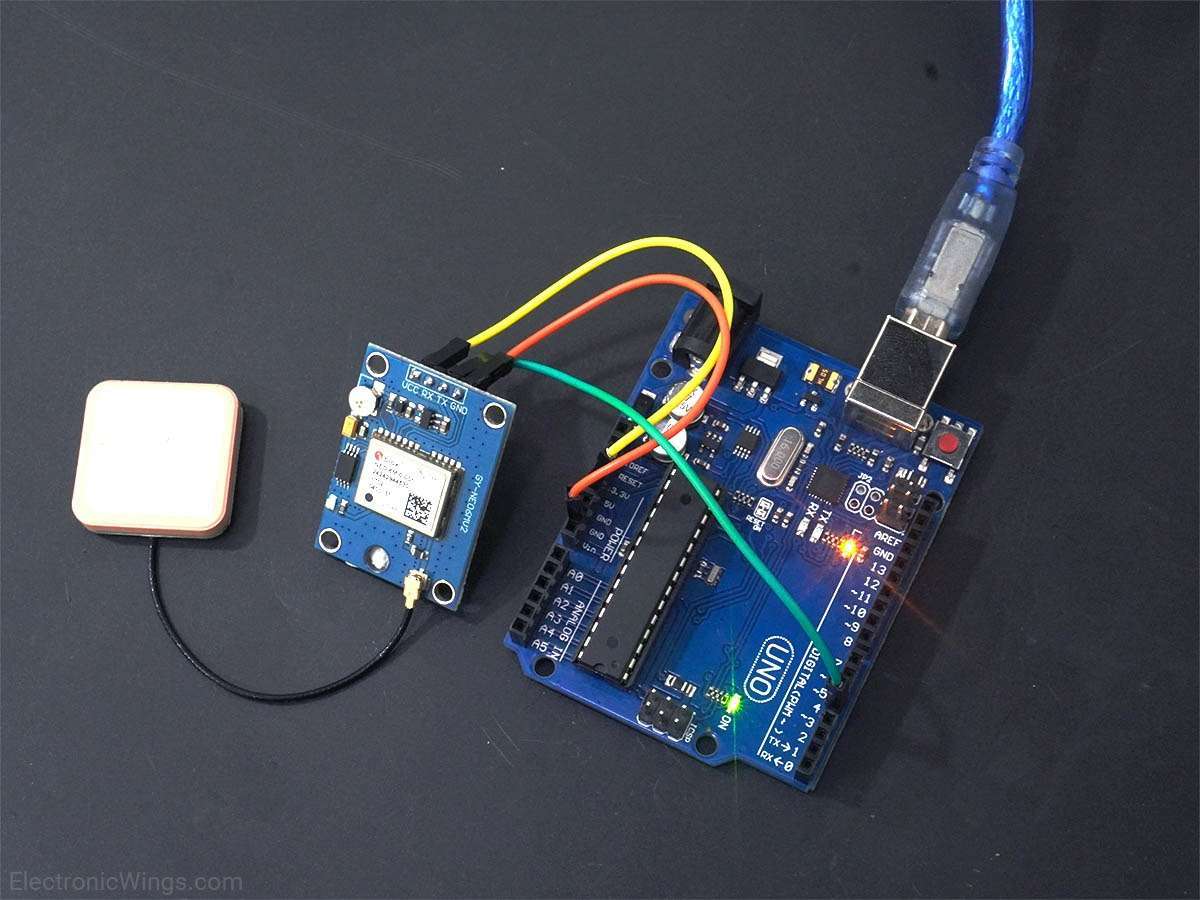
Are NexPCB Displays Modules Compatible With Arduino
Yes. Most NexPCB display modules can be driven from an Arduino, provided three things line up: the interface the module exposes, the logic level it accepts, and a library that matches its controller. Modules with I2C or SPI and a 3.3 V-tolerant controller are the straightforward case. Parallel panels are not excluded, but they need more pins than a small board has.
Interface is the first filter
Every module falls into one of three groups. Serial modules expose I2C or SPI and need two to five signal lines. Parallel modules expose an 8080 or 6800 bus and need a dozen or more. Bare RGB panels have no controller at all and expect a continuous pixel stream with its own clock and sync.
The groups differ in cost as much as in wiring. I2C is cheapest in pins and slowest in throughput, because every byte travels over one data line. SPI trades a few more pins for a much higher clock, and a parallel bus is fast but pin-hungry.
Serial modules also carry a controller with its own display RAM. That matters more than the interface, because the host sends a frame once and the module holds it.
Logic level is the second filter
An Uno runs its I/O at 5 V. Many display controllers run at 3.3 V and are not specified as 5 V tolerant, so a direct connection puts the controller outside its ratings even when it appears to work. Two arrangements are acceptable: a module with an on-board regulator and level shifting, or an external level shifter on the signal lines.
What is not acceptable is the resistor divider shortcut on the data line alone. It leaves the pull-ups on the bus pulling to 5 V, and it does nothing for the return path. A four-channel bidirectional shifter costs less than the module and removes the question entirely.
Power is a separate decision from logic. A module rated for a wide supply range can take 5 V on VCC while its logic pins remain 3.3 V devices, and the datasheet is the only reliable guide to which pins belong to which domain.
Wiring a four-wire module
Four-wire I2C modules are labelled VCC, GND, SCL and SDA, and the labels are usually printed on the silkscreen. The pin positions differ between manufacturers, so wire by label rather than by position, and check the order once more before applying power.
| Module pin | Function | Uno | Mega 2560 |
|---|---|---|---|
| VCC | Supply | 5 V or 3.3 V per datasheet | Same |
| GND | Ground | GND | GND |
| SCL | Clock | A5 | D21 |
| SDA | Data | A4 | D20 |
Those pin assignments are board-specific rather than universal: Leonardo uses D2 and D3, and the MKR series uses D11 and D12. The Arduino reference for the Wire library lists the default I2C pins for each board, which is worth checking before assuming an Uno pinout.[1]
Addresses and bus conflicts
The Wire library works in 7-bit addresses, and addresses below 8 are reserved, so the first usable device address is 8.[1] Many 128×64 OLED modules built on the common SSD1306 controller answer at 0x3C, with 0x3D as the alternate selected by a resistor or a solder bridge on the back of the board.
Two devices at the same address cannot share a bus. When a second module is added, either change its strap or move it to a second bus where the board provides one. A scanner sketch that reports nothing usually means wiring or power, and a scanner that reports an unexpected address usually means the module is strapped differently from the listing.
The buffer limit nobody reads
The Wire library holds a 32-byte buffer, and bytes beyond that in a single transmission are dropped.[1] A full 128×64 monochrome frame is 1,024 bytes, so it cannot be sent in one call. Libraries handle this by splitting the frame into pages or chunks, and hand-written code has to do the same.
The symptom of getting it wrong is characteristic: the first part of the screen updates, the rest keeps whatever was there before. If a display shows a correct top strip and a stale bottom, the buffer is the first thing to check.
Wire timeouts are also worth enabling. Recent versions of the library can time out on a stuck bus, but the feature is off by default, and a display that holds SDA low will otherwise hang the sketch rather than return an error.[1]
SPI modules need five lines
An SPI display adds a chip-select, a data/command line and usually a reset, on top of clock and data. Most modules do not need the return data line, since the host only writes. On an Uno the hardware SPI pins are fixed, which is convenient, and any other pin can serve as chip select and data/command.
The gain is throughput: a serial clock in the megahertz range moves a full frame in a fraction of the time I2C needs. The cost is three more wires and a slightly more involved library setup, since the constructor has to be told which pins carry chip select, data/command and reset.
Keep the wires short at higher clocks. A breadboard with long jumpers adds capacitance and inductance that show up as occasional corrupted frames rather than as a clean failure, which is the hardest kind of fault to chase.
Parallel and RGB panels
An 8-bit parallel bus needs eight data lines plus control, read and write strobes, and often a reset. That is most of an Uno's digital header before anything else is connected. A Mega has enough pins, and larger modules with their own display RAM and a parallel interface are usually paired with it.
Bare RGB panels belong in a different category. They have no frame buffer, so the host must supply pixels continuously with correct timing, which an Arduino cannot do at any useful resolution. The practical answer is a controller board that generates the timing and exposes a simpler interface. The TFT module range shows the distinction, since most parts there include a controller with a serial or parallel host interface.
Memory is the real constraint
An Uno has 2 KB of SRAM, and a 1,024-byte frame buffer consumes half of it before the sketch allocates anything else. Text-only modules avoid the problem because the controller stores characters itself. Graphic modules do not, which is why graphics libraries offer a page-buffer mode that renders one horizontal band at a time.
That mode is the reason many small displays work at all on an AVR board. The trade-off is that drawing outside the current page needs a second pass, so animations show as they are composed.
Powering the module
Small monochrome modules draw little enough to run from the board's regulated rail. Colour TFT modules with a backlight do not: the backlight alone can exceed what the on-board regulator is rated for, and the result is a brown-out that resets the microcontroller whenever the screen brightens.
Give any backlit module its own supply, share the ground, and switch the backlight through a transistor rather than from a GPIO pin. A pin rated for a few tens of milliamps will not survive a backlight string, and the failure is usually the pin rather than the module.

When it does not work
| Symptom | Likely cause | Check |
|---|---|---|
| Scanner finds nothing | Wiring, power or pull-ups | Rail voltage, then SDA and SCL continuity |
| Address present, screen blank | Initialisation or contrast register | Library constructor, then contrast value |
| Top strip updates, rest stale | Transmission longer than the buffer | Send in pages of 32 bytes or less |
| Random corruption | Long leads or shared pull-ups | Shorten wiring, count the pull-ups |
| Resets when the screen brightens | Backlight current on the board rail | Separate supply and a switching transistor |
| Sketch hangs | Bus held low, no timeout | Enable the Wire timeout |
For character-based parts the integration is simpler still, because the controller owns the font and the host sends text rather than pixels; the character OLED range is the place to start when a project only needs numbers and short labels.
Compatibility comes down to three matches: interface, logic level and controller library. Get those right and an Arduino drives most display modules without any custom driver. Check the datasheet's pin domains before applying power, and the rest is firmware.
References
- Arduino. Wire — Arduino Language Reference (I2C communication, default pins per board, 7-bit addressing, 32-byte buffer, timeouts). https://docs.arduino.cc/language-reference/en/functions/communication/wire/
Weiterlesen
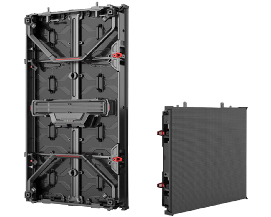
For Standard XR Display Modules, purchase options include major e-commerce platforms like Amazon , which hosts 200+ verified suppliers with an average.
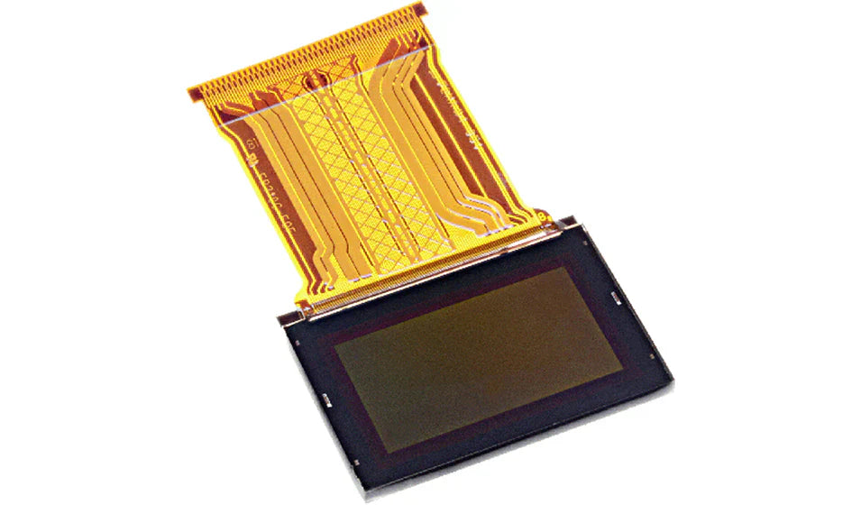
Micro OLED modules, commonly used in compact AR/VR devices and wearables, generally feature resolutions from 1280×720 pixels in entry-level models to.
Hinterlasse einen Kommentar
Diese Website ist durch hCaptcha geschützt und es gelten die allgemeinen Geschäftsbedingungen und Datenschutzbestimmungen von hCaptcha.