









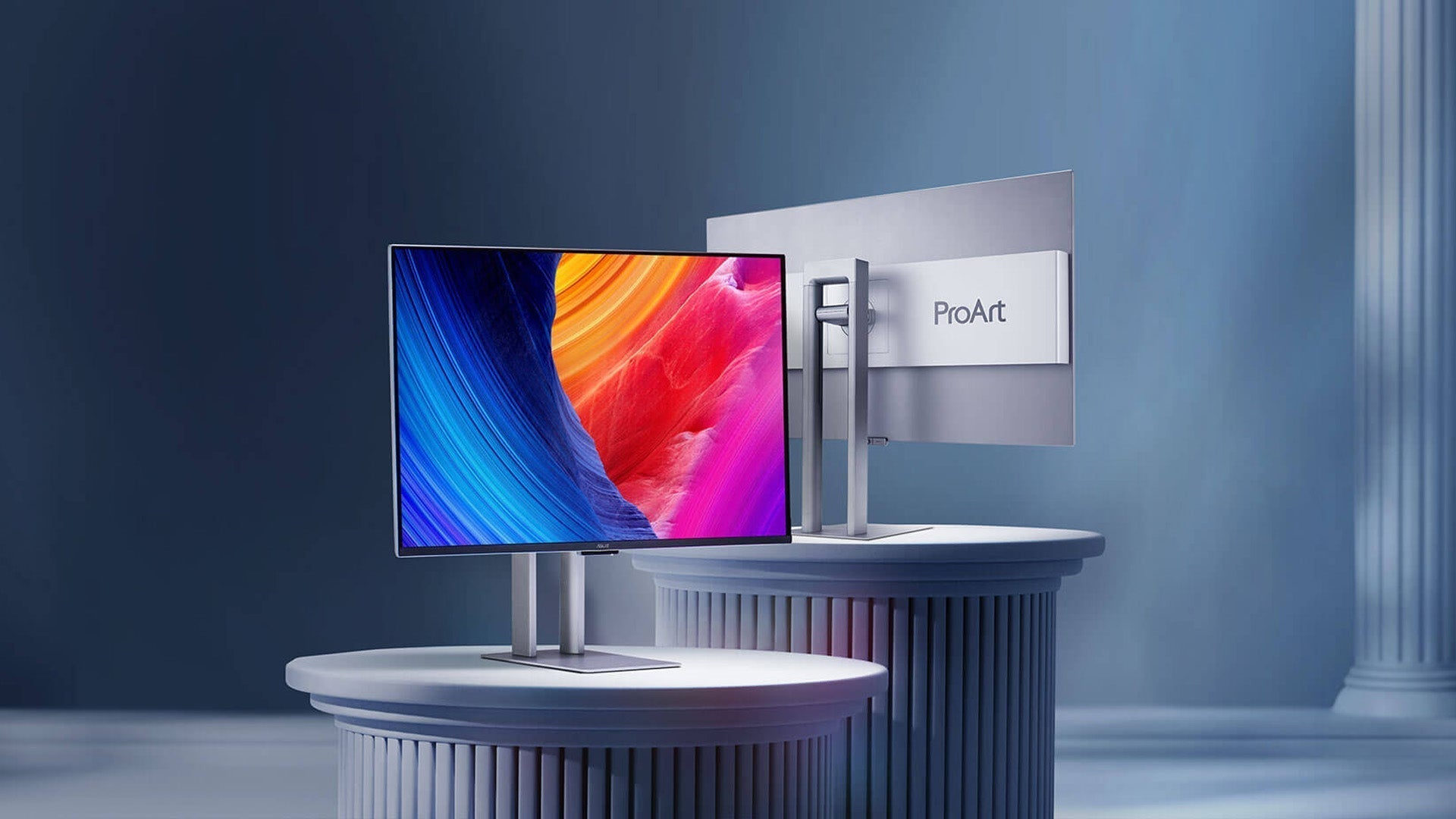
Character OLED Displays: A Comprehensive Guide to Working Principles and Design-In
A character OLED display is a small self-emissive module that draws characters from a built-in font instead of arbitrary graphics. The panel, a passive-matrix driver and a controller with character ROM sit in one package, and the host writes to it over I²C or SPI. Choose one by font cell size, controller family, interface budget, temperature range and stated lifetime conditions.
What sits inside the module
Three parts decide what you can do with the part. The glass carries a passive-matrix grid of organic pixels. A controller IC holds the frame buffer, the font ROM and the charge pump. A flex tail or pin header exposes supply, ground, reset and the serial bus.
Because the font patterns live in ROM, the host does not send bitmaps for ordinary text. You send a character code, and the controller copies the matching pattern into the buffer at the cursor position. That is why a character module needs almost no RAM on the host side, and why it suits timers, sensor readouts and status panels where a full graphics stack would be overkill.
How the pixels emit light
An OLED is a stack of thin organic layers between two electrodes. The anode injects holes, the cathode injects electrons, and the two meet in an emissive layer where they recombine and release photons. Separate hole and electron transport layers steer each carrier type toward the emissive layer so that recombination happens where it is wanted.[2]
Light appears within microseconds of current flow because the conversion is direct. There is no liquid-crystal reorientation to wait for and no backlight to modulate, so an unlit pixel is genuinely dark. That is the structural difference from an LCD: the black state does not depend on a shutter holding light back.

Passive matrix addressing
Character modules are commonly built around passive-matrix drive. Columns and rows are driven directly, with no transistor at each pixel. The controller energises one row at a time, sets the column currents for the pixels that should light on that row, then moves on.
Duty cycle follows from the row count. A 64-row panel gives each row roughly one sixty-fourth of the frame time, so the instantaneous drive has to be far above the perceived brightness. That trade-off sets the practical ceiling on size and resolution: more rows mean shorter pulses, higher peak current and faster aging. Passive matrix is the reason character OLEDs occupy the small-panel range rather than competing with graphics modules.
Controller and font ROM
A controller in the SSD1306 family integrates display RAM, font ROM, charge pump and timing generator. On a 128×64 panel the buffer is 1,024 bytes, one bit per pixel, so buffer size and pixel count are the same number viewed two ways.
Font ROMs usually carry a 5×7 or 5×8 glyph cell plus a column of spacing, which is what allows twenty-one characters across a 128-pixel row. Taller variants use 8×16 cells for numeric readouts meant to be read at a distance. Confirm the exact cell size, character count and supported code pages in the controller datasheet before you fix the layout, because the font table and not the panel is what limits your text.
Since one bit maps to one pixel, partial updates are cheap. Rewriting a single changed value costs a handful of bytes, while a full refresh of a 128×64 buffer costs a kilobyte plus command overhead. Designs that update every field on every cycle waste most of that bandwidth.
Interface choices
I²C keeps the wiring to four conductors and is the default for a single board with a short run. SPI needs more pins but moves far more data. Neither is better in isolation; the answer depends on three numbers together — target update rate, colour depth and bus clock.
Run the arithmetic before committing. A monochrome 128×64 frame is 1,024 bytes, and at a 400 kHz I²C clock the payload alone occupies tens of milliseconds once addressing and control bytes are counted. Smooth full-screen animation at video rates is out of reach on that bus. Refreshing a few characters several times per second is comfortable. SPI clocked in the megahertz range changes the picture, and if you genuinely need motion, the module class is wrong rather than the interface.
Check logic levels in both directions. A 5 V host driving a 3.3 V module needs level shifting on the signal lines, and a 3.3 V host with a module specified for 5 V logic is a separate problem. Module datasheets rarely spell this out, so read the controller datasheet as well.
Supply and decoupling
Most character modules run from a single 3.3 V rail and generate the higher OLED drive voltage internally. Current draw tracks the lit-pixel count: a screen showing a few characters draws a fraction of what an all-pixels-on test pattern needs, which matters when you size a battery or a regulator.
Place a 100 nF ceramic capacitor within a few millimetres of the supply pins and add a bulk capacitor of a few microfarads nearby. The charge pump draws current in fast steps, and a long thin supply trace turns those steps into rail droop that appears as flicker or an unexplained controller reset.
Power-up sequence
Bring the supply up, then wait for the internal regulator to stabilise before the first command. Datasheets specify a delay from supply valid to first command in the AC characteristics table; treat it as a minimum, not a target.
Reset timing matters for the same reason. Hold the reset line low for at least the stated pulse width, and copy the vendor's initialisation table in the order given rather than tidying it. A module that stays dark after a plausible-looking init sequence usually has a timing fault, not a wiring fault.
Set contrast deliberately. Maximum contrast raises current and accelerates aging, so a mid-scale value is usually enough for indoor use and leaves headroom for a bright room.
Lifetime and burn-in
Organic emitters fade as charge accumulates, and the colour systems do not fade at the same rate. Blue is the usual constraint in a full-colour stack, which is why white-point drift shows up long before total failure. Monochrome modules avoid differential aging between colours but still lose luminance with hours of operation.
Ask what test condition a lifetime figure refers to: initial luminance, constant-current or constant-voltage drive, duty cycle, and the definition of end of life. Luminance and contrast are only comparable when the measurement conditions are stated, which is the point of standardised display measurement.[1] An unqualified hour count is a marketing number.
Static content is the practical risk. A fixed colon, a logo or a border that does not move ages the same pixels continuously while the rest of the panel rests. Blank the panel after a period of inactivity, shift static elements by a pixel or two on a schedule, and reduce brightness in a dark room. None of these cost anything at design time.
Selection checklist
- Resolution and glyph cell size that fit your longest line without scrolling.
- Controller family, because your driver library is tied to it.
- Interface with the bus budget checked against your real update rate.
- Operating temperature range covering the coldest start and the hottest soak your enclosure will see.
- Outline dimensions, mounting holes and connector orientation relative to the window.
- Lifetime and luminance conditions stated explicitly by the supplier.
Standard parts in several sizes and colours are listed in our character OLED collection, and related passive-matrix parts appear in the PMOLED range. For modules that need graphics rather than text, the graphic OLED collection covers the same interface families at higher pixel counts.
A character OLED rewards early decisions: pick the controller and the interface before the enclosure, confirm the font cell against your longest string, and design the supply and the blanking routine as part of the schematic rather than as a firmware patch.
References
- ISO 9241-307:2008 — Ergonomics of human-system interaction — Part 307: Analysis and compliance test methods for electronic visual displays. International Organization for Standardization. https://www.iso.org/standard/40102.html
- Hilsum, C. (2010). Flat-panel electronic displays: a triumph of physics, chemistry and engineering. Philosophical Transactions of the Royal Society A, 368(1914), 1027–1082. https://doi.org/10.1098/rsta.2009.0247
Weiterlesen
2025’s character OLED guides highlight self-emissive tech (1000:1 contrast, μs response), used in industrial dashboards/smart home panels. Select via.
Character OLEDs use I2C/SPI interfaces (100kHz/1MHz), paired with SSD1306/SH1106 controllers. Drive via 3-5V, ~20mA; initialize with commands (set.
Hinterlasse einen Kommentar
Diese Website ist durch hCaptcha geschützt und es gelten die allgemeinen Geschäftsbedingungen und Datenschutzbestimmungen von hCaptcha.