


COG LCD Display Module | Medical Devices, Instruments, Low-Power Products
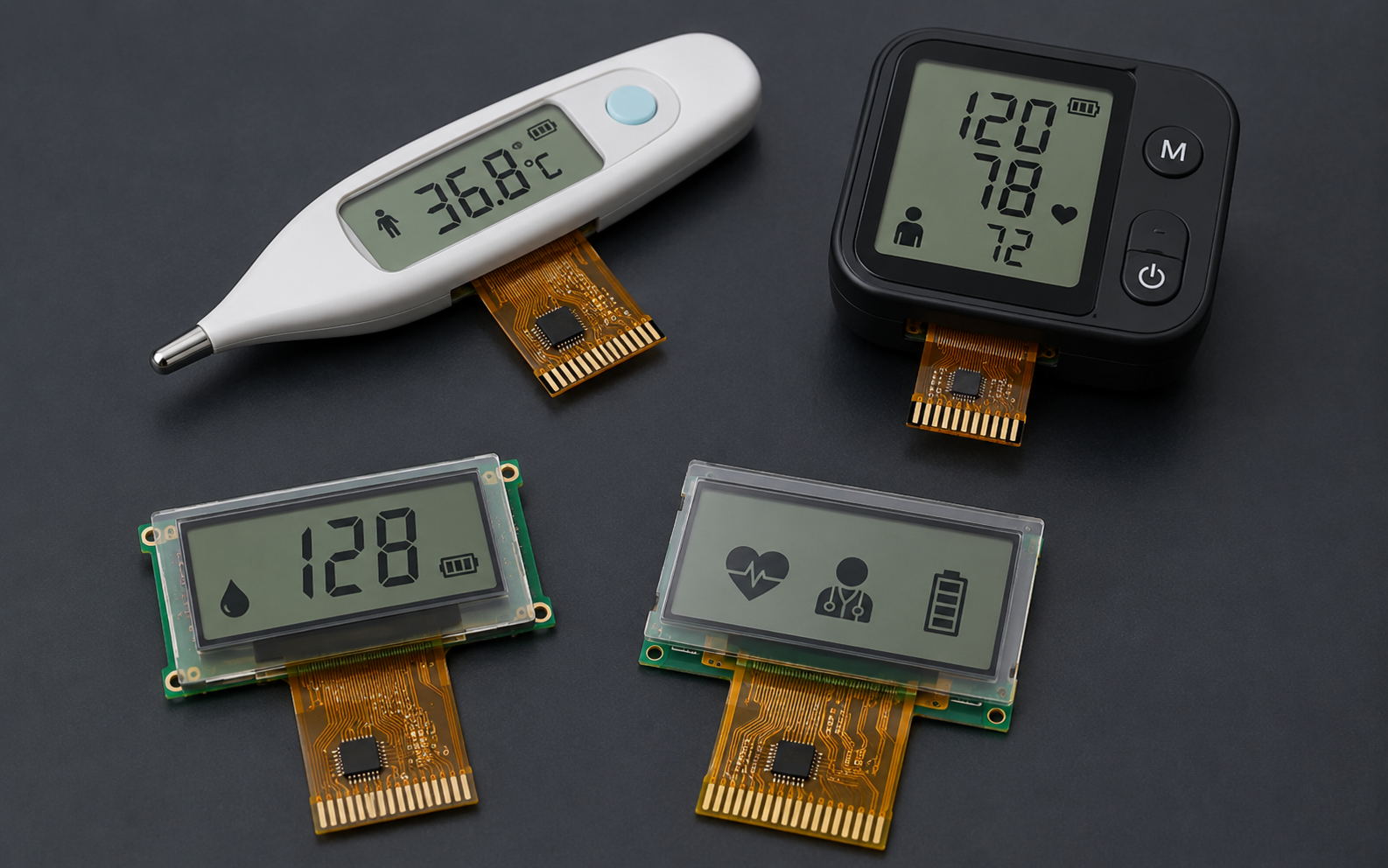
COG LCD display modules are widely used in compact products that need low power consumption, stable readability, simple MCU integration, and a thin mechanical structure. Typical applications include medical measurement devices, handheld instruments, industrial meters, thermostats, access-control products, wireless sensors, home appliances, and other battery-powered equipment.
COG stands for Chip-on-Glass. In a COG LCD module, the LCD driver IC is bonded directly onto the glass substrate instead of being mounted on a separate PCB. This structure can help reduce module thickness, shorten signal paths, and simplify the mechanical stack. However, the final display performance still depends on the selected LCD mode, resolution, controller IC, interface, backlight, voltage, operating temperature, viewing direction, firmware initialization, and the customer’s device-level design.
DisplayModule provides standard COG LCD modules for sample evaluation and bulk supply. Public product examples include 16×2 character COG LCDs, 20×2 character COG LCDs, 128×32 graphic COG LCDs, and 128×64 graphic COG LCDs with SPI, I²C, MCU, 8080, or 6800 interface options depending on the selected model. Before design-in, engineers should confirm the official product page, drawing, datasheet, interface timing, controller IC documentation, and sample test results.

Module Basics
Size Selection
COG LCD size selection should start with the information that must appear on the screen. A product that only displays numbers, units, and simple status messages may work well with a character LCD. A product that needs icons, menus, small charts, or custom bitmap fonts should use a graphic LCD.
The display diagonal or character count is not enough for mechanical design. Engineers should confirm the module outline, viewing area, active area, thickness, pin or FPC position, connector type, viewing direction, mounting structure, bezel allowance, and the space required by the enclosure window. In compact medical devices and handheld meters, even a small difference in module thickness or connector position can affect the PCB layout, gasket design, battery placement, and assembly process.
For example, a 16×2 SPI COG LCD module can use a compact 41.4 × 24.3 × 4.0 mm maximum module size, 3.0 V supply, STN blue negative transmissive mode, edge white LED backlight, SPI interface, and ST7032 or equivalent controller IC. This type of module is suitable for simple text and numeric interfaces where a compact footprint and low pin count are important.
A 128×32 SPI graphic COG LCD can provide more layout flexibility while keeping a compact module size. One public example uses 128×32 resolution, FSTN transflective technology, 4-line SPI MPU interface, ST7565R controller IC, 3.0 V power supply, 41.4 × 24.3 × 4.0 mm maximum module dimension, and 5.6 g weight. This format can display icons, small menus, sensor values, and simple status graphics.
For more screen area, 128×64 COG LCD modules are commonly used in instruments and industrial controls. A 2.61-inch example uses 128×64 resolution, FSTN transflective technology, ST7565R controller IC, 8080/6800 MPU interface, 3.3 V ± 0.3 V power supply, edge white LED backlight, and -20°C to +70°C operating temperature. A 3.07-inch example uses 128×64 resolution, STN negative blue transmissive mode, ST7565P controller IC, parallel or serial MPU interface, 3.0 V power supply, and white LED backlight.
| Example Module Type | Format / Resolution | Interface | Controller IC | Typical Design Use |
|---|---|---|---|---|
| Character COG LCD | 16×2 characters | SPI or I²C, depending on model | ST7032 / ST7032I or equivalent | Simple values, units, menu labels, and status text |
| Character COG LCD | 20×2 characters | I²C | ST7036I | Longer text labels and compact instrument interfaces |
| Graphic COG LCD | 128×32 pixels | 4-line SPI MPU | ST7565R | Icons, compact dashboards, and simple graphic UI |
| Graphic COG LCD | 128×64 pixels | 8080/6800 MCU or serial interface, depending on model | ST7565R / ST7565P | Meters, industrial instruments, multi-line menus, and basic graphics |
A practical size-selection workflow is: define the required content, choose character or graphic format, check the module outline and viewing window, confirm the interface and voltage, review viewing direction and backlight, then order samples for mechanical and electrical validation.
Use Cases
COG LCD modules are suitable for products where the display must be compact, efficient, and easy to integrate. They are not a universal replacement for TFT, OLED, or ePaper. The correct choice depends on the user interface, lighting condition, power budget, viewing distance, operating temperature, and product lifecycle.
- Medical measurement devices: blood pressure monitors, glucose meters, thermometers, handheld diagnostic tools, and portable monitoring accessories may use COG LCDs for clear numeric display and low power operation. Medical compliance, cleaning resistance, electrical safety, and usability validation remain device-level responsibilities.
- Industrial instruments: panel meters, counters, thermostats, data loggers, process controllers, and handheld test tools often need stable text or monochrome graphics in a compact display window. Selection should focus on viewing direction, contrast, temperature range, backlight behavior, and interface stability.
- Battery-powered products: wireless sensors, locks, remote controllers, portable tools, and low-duty-cycle devices can benefit from low LCD logic current and simple MCU control. Backlight current should always be calculated separately.
- Consumer and home devices: appliances, chargers, audio equipment, smart-home panels, and small control boxes may use COG LCDs when the UI is simple and color is not required.
Requirements such as IP rating, drop resistance, chemical cleaning, EMC, ESD, and enclosure sealing should be treated as device-level requirements. The LCD module supports the system design, but waterproofing, impact protection, cleaning durability, and regulatory compliance depend on the final cover lens, gasket, adhesive, enclosure, PCB, firmware, and assembly process.
Power Consumption Constraints
COG LCD power consumption should be separated into LCD logic current and backlight current. The LCD driver may consume a small current during normal display operation, while the LED backlight can become the largest display-related load when it is turned on.
Public product examples show why the selected model matters. A 128×32 SPI COG LCD example lists 3.0 V operation and 0.25 mA typical consumption current. A 16×2 SPI COG LCD example lists 0.3 mA typical current at 3.0 V. A 16×2 I²C transflective COG LCD example lists 0.18 mA typical operation current at 3.3 V, while its white LED backlight is listed separately. These values are model-specific and should not be generalized to every COG LCD module.
The backlight should be measured as a separate circuit. White edge LED backlights are common in compact COG LCD modules, but current depends on LED configuration, forward voltage, current-limiting resistor or constant-current driver, PWM duty cycle, brightness target, and ambient-light strategy. For battery-powered products, firmware should avoid keeping the backlight on continuously unless the use case requires it.
| Power Item | What to Check | Why It Matters |
|---|---|---|
| LCD logic current | Driver IC current, voltage, display mode, sleep mode | Defines baseline display consumption |
| Backlight current | LED current, PWM duty, brightness level, driver circuit | Often the largest display current in low-light use |
| Standby current | LCD sleep mode, MCU sleep mode, leakage paths | Critical for long-life battery products |
| Startup current | Initialization, reset timing, charge pump, backlight ramp | Prevents unstable startup or brownout |
| Temperature behavior | Current, contrast, response, and backlight behavior at temperature limits | Important for industrial and outdoor equipment |
A recommended power test should include display off, display on without backlight, display on with backlight at several PWM levels, sleep mode, wake-up, and a full battery-life simulation using the real product duty cycle. Record supply voltage, current, ambient temperature, contrast setting, backlight duty cycle, MCU state, and firmware version in the same test log.
Display Features
Resolution
COG LCD modules can be divided into character displays and graphic displays. Character displays are simpler to drive and are suitable for numbers, letters, units, and basic menu text. Graphic displays provide pixel-level control and are better for icons, custom fonts, progress bars, simple diagrams, and multi-line UI layouts.
Character formats such as 16×2 and 20×2 reduce firmware complexity because the layout is character-based. Graphic formats such as 128×32 and 128×64 require the MCU to manage pixels, pages, font libraries, display buffers, and update timing.
| Display Format | Best For | Firmware Consideration | Main Limitation |
|---|---|---|---|
| 16×2 character | Simple numeric values, units, status labels | Low complexity | Limited layout flexibility |
| 20×2 character | Longer labels and two-line text screens | Low to medium complexity | No flexible bitmap layout |
| 128×32 graphic | Icons, compact dashboards, small sensor UI | Requires pixel or page-based drawing | Limited vertical UI space |
| 128×64 graphic | Menus, meters, multiple values, simple charts | Requires more display memory and refresh planning | Higher firmware workload than character LCD |
For monochrome graphic LCDs, memory requirements can be estimated from pixel count. A 128×32 1-bit frame buffer requires 512 bytes of RAM. A 128×64 1-bit frame buffer requires 1,024 bytes of RAM. If the MCU has limited RAM, the firmware can update the display page by page, but this may increase code complexity and affect refresh behavior.
Resolution should be selected by content density and viewing distance. Before choosing a module, list every value, unit, icon, warning, and menu label that must appear on the screen. Then test the layout using the actual font size, expected viewing distance, and device orientation. A display that seems large enough in a spreadsheet may still be hard to read if the font is too small, the contrast is low, or the viewing direction does not match the product orientation.
Brightness Range
COG LCD readability depends on LCD mode, polarizer, backlight, contrast setting, viewing direction, cover lens, ambient light, and the user’s viewing angle. Unlike OLED, an LCD does not emit light from each pixel. It modulates light from the backlight, ambient light, or both, depending on whether the display is transmissive, reflective, or transflective.
Transmissive LCDs rely on a backlight and are suitable for controlled indoor lighting or devices that need a lit display in dark environments. Transflective LCDs use both ambient light and backlight, which can be useful for products that must be readable across different lighting conditions. Public COG LCD examples include STN blue negative transmissive, FSTN positive transflective, and FSTN transflective display technologies.
Brightness should not be described with one universal value for all COG LCD modules. A fixed statement such as “300 to 500 cd/m² is readable in direct sunlight” can be misleading unless it is measured with the final module, cover lens, backlight setting, optical stack, and ambient-light condition. Outdoor readability depends on contrast, reflection, viewing angle, surface treatment, font size, and user distance, not only on luminance.
- No backlight or backlight off: useful only when ambient light and LCD mode provide enough readability.
- Standard LED backlight: improves readability in indoor or low-light conditions but increases current consumption.
- PWM dimming: helps balance readability and power, but the PWM frequency should avoid visible flicker and system noise issues.
- Cover lens and bonding: can improve mechanical protection but may reduce readability if reflections are not controlled.
- Viewing direction: must match how the final device is held, mounted, or viewed.
For engineering validation, record luminance, contrast, viewing angle, ambient light, backlight current, PWM setting, cover lens condition, and test pattern. LCD optical measurement should use defined conditions and calibrated equipment rather than subjective visual judgment alone.
Interface Types
The display interface affects MCU pin count, update speed, firmware structure, FPC routing, and EMI behavior. DisplayModule COG LCD examples include SPI, I²C, 6800 MCU, and 8080 MCU interfaces depending on the selected product. The interface should always be confirmed per model instead of assuming one default interface for the whole COG LCD category.
SPI is useful when the MCU has limited pins and the UI does not require frequent full-screen updates. I²C is convenient for character LCDs and low-pin-count systems, but it is usually not the first choice for high-refresh graphic screens. 6800 and 8080 parallel interfaces require more pins but can support faster updates and simple timing control in many MCU systems.
| Interface | Typical Benefit | Main Trade-Off | Typical Use |
|---|---|---|---|
| SPI | Low pin count and simple wiring | Lower throughput than parallel interfaces | 16×2 character LCDs, 128×32 graphics, compact 128×64 UI |
| I²C | Two-wire connection and shared bus | Limited speed and bus-address management | Simple character display applications |
| 6800 MCU | Parallel data transfer and flexible control | More MCU pins required | Graphic LCD modules where update speed matters |
| 8080 MCU | Common parallel display-controller interface | More routing and pin count than serial interface | 128×64 graphic LCDs and instrument interfaces |
Before schematic design, confirm the controller IC, interface mode, voltage level, reset pin, chip-select pin, data/command selection, read/write timing, backlight pins, and initialization sequence. For graphic LCDs, also confirm whether the MCU has enough RAM and processing time for the intended refresh rate.
A safe interface workflow is: select the target module, read the datasheet, check host voltage compatibility, confirm pin count, verify firmware support for the controller IC, build a prototype driver, test full-screen update time, then lock the schematic and FPC routing.
Production Support
Sample Validation
Sample validation should prove that the selected COG LCD module works inside the real device, not only on a bench test board. Standard samples are useful for early evaluation, but final approval should include the actual enclosure, final PCB, real firmware, power supply, backlight circuit, cover lens, gasket, and assembly method.
A practical validation plan should include specification review, mechanical fit check, electrical bring-up, firmware display test, contrast adjustment, backlight test, power measurement, visual inspection, temperature test, and user readability review. For medical, industrial, or outdoor products, additional device-level validation may be required by the customer’s regulatory or quality system.
| Validation Step | What to Check | Recommended Evidence |
|---|---|---|
| Datasheet review | Resolution, module size, voltage, interface, controller, temperature range | Marked datasheet and requirement checklist |
| Mechanical fit | Window alignment, outline, thickness, FPC path, connector clearance | Photos, drawing overlay, and assembly notes |
| Electrical bring-up | Power sequence, reset timing, communication, initialization, contrast setting | Scope captures and firmware version record |
| Display quality | Missing lines, contrast, viewing direction, uniformity, backlight, defects | Inspection record and sample photos |
| Power test | Display-on current, backlight current, sleep current, wake-up behavior | Current log under defined operating modes |
| Temperature check | Cold start, high-temperature operation, contrast drift, response behavior | Test condition, duration, result, and failure photos if any |
LCD testing should be tied to recognized standards when appropriate. IEC 61747-1-1 provides a generic specification framework for liquid crystal display devices, including electrical and optical characteristics, climatic and mechanical tests, and endurance tests. IEC 61747-30-1 covers measurement methods for transmissive LCD modules, including transflective modules with backlights on. Temperature-change testing can be planned with reference to IEC 60068-2-14 when the product must withstand changing ambient temperatures.
Pixel and appearance acceptance should be defined before mass production. Avoid promising “zero defects” unless a special inspection class and commercial agreement support that requirement. Pixel defects, line defects, scratches, stains, bubbles, foreign material, contrast variation, and backlight non-uniformity should be controlled by an agreed inspection standard or customer-specific quality agreement.
Customization Services
Customization can include display format, FPC or pin assignment, backlight, interface support, cover lens, surface treatment, connector choice, packaging, and driver-board development. However, customization scope, MOQ, cost, and lead time should be confirmed by model and project requirements. They should not be stated as one fixed number for all COG LCD products.
DisplayModule’s public information supports standard module supply, direct sample purchase, bulk supply, custom display and driver-board solutions, and engineering assistance. Its COG LCD category also states that standard display modules are available for direct sample purchase, while bulk pricing, MOQs, and lead time depend on the selected model and quantity.
A reliable customization inquiry should include:
- Target product type and estimated annual quantity
- Preferred display format or resolution
- Required module outline, viewing area, and maximum thickness
- Interface requirement: SPI, I²C, 6800, 8080, or other MCU interface
- Operating voltage and host MCU model
- Backlight color, brightness target, and dimming requirement
- Viewing direction and intended mounting orientation
- Operating temperature and storage temperature requirements
- Cover lens, surface treatment, touch requirement, or sealing requirement
- Required documentation, inspection standard, and packaging requirement
Recommended customization flow: requirement review → standard model comparison → datasheet and drawing confirmation → sample purchase or prototype build → firmware bring-up → optical and power validation → reliability review → quality agreement → pilot order → production order.
For products with strict temperature, long service life, cleaning, or outdoor requirements, the display should be tested under real product conditions. Wide-temperature operation, alcohol wiping, high humidity, outdoor exposure, or repeated mechanical stress should not be assumed from a general product description unless the selected module and final assembly have been validated for those conditions.
Mass Production Assurance
Mass production assurance should be based on documented process control and agreed inspection criteria. For COG LCD modules, important production concerns include glass handling, COG bonding quality, FPC or pin alignment, backlight assembly, visual defects, electrical testing, packaging, ESD protection, and traceability.
Unsupported statements such as fixed monthly capacity, fixed yield, no stockout history, exact AOI precision, guaranteed miss rate, or one universal lead time should not be used unless they are supported by current factory documentation and an approved quality agreement. A more accurate public statement is that bulk orders, lead times, MOQs, and delivery plans should be confirmed by the selected model, quantity, material availability, and customization scope.
The production quality plan should define:
- Incoming material control: glass, driver IC, polarizer, backlight, FPC, connector, and packaging materials.
- Process control: COG bonding parameters, alignment, cleaning, handling, and ESD protection.
- Electrical test: power, communication, display pattern, missing line, contrast, sleep, and wake-up behavior.
- Optical and visual inspection: contrast, uniformity, scratches, stains, foreign material, bubbles, white spots, black spots, and line defects.
- Reliability test: temperature operation, storage, humidity, temperature change, backlight aging, and FPC bending if required.
- Traceability: lot number, inspection record, date code, packaging label, and failure-analysis process.
Pixel defect rules should be written into the purchase specification or quality agreement. ISO 9241-307 is commonly referenced for pixel defect classification in flat-panel displays, but the exact class, inspection distance, ambient light, test pattern, and acceptance method should be agreed between supplier and customer.
For stable production, the customer should lock the approved sample, drawing, firmware version, backlight setting, contrast setting, packaging requirement, and inspection criteria before the pilot build. Any change to controller IC, interface, FPC routing, backlight, LCD mode, polarizer, or mechanical stack should trigger a design review and, when necessary, new validation.
A production-ready COG LCD project is not defined only by resolution or price. It should have a verified module, confirmed electrical interface, readable UI, measured power profile, validated backlight behavior, approved mechanical fit, agreed quality criteria, and a supply plan that matches the project volume and lifecycle.
Hinterlasse einen Kommentar
Diese Website ist durch hCaptcha geschützt und es gelten die allgemeinen Geschäftsbedingungen und Datenschutzbestimmungen von hCaptcha.