


Custom AMOLED Display Manufacturer | Wearables, Handheld Devices
DisplayModule supplies standard AMOLED display modules and supports bulk procurement, custom display integration, FPC modification, cover glass customization, driver-board development, and engineering support for product teams. This article covers practical AMOLED selection questions for wearable devices, handheld terminals, smart equipment, and compact visual interfaces, with focus on screen size, active area, interface, touch integration, brightness, power, validation, and production planning.
AMOLED stands for Active Matrix Organic Light Emitting Diode. Unlike LCD modules, AMOLED pixels are self-emissive, so there is no backlight layer. This affects power behavior, module stack-up, optical design, lifetime evaluation, and user-interface strategy. For any design-in project, final decisions should be based on the official drawing, datasheet, interface timing, power sequence, and sample validation of the selected module.

Project Basics
Screen Size
When selecting or customizing an AMOLED module, the display diagonal is only the starting point. Mechanical engineers should confirm the active area, panel outline, module thickness, FPC position, connector direction, viewing window, cover glass size, and tolerance stack-up before the enclosure is finalized.
Active area is especially important because it defines the real visible image area. A 1.39-inch round display, a 2.4-inch rectangular display, and a 3.92-inch handheld display can have very different active-area shapes, interface requirements, and mechanical constraints even when they are all described as AMOLED modules.
For example, one DisplayModule 1.39-inch round AMOLED module lists a 454×454 resolution, 35.41×35.41 mm active area, 42(H)×42.6(W)×2.227(D) mm module size, 350 cd/m² typical luminance, capacitive touch, MIPI/SPI interface, 3.3 V supply voltage, and SH8601A driver IC. This type of compact round module is suitable for wearable interfaces where high pixel density, touch response, and thin mechanical design matter.
For handheld equipment, a 2.4-inch AMOLED module may use a 450×600 resolution, 36.72×48.96 mm active area, 311 PPI pixel density, SPI/MCU/MIPI DSI interface, LTPS backplane, and RM690B0 driver IC. Another 2.4-inch option lists 450×600 resolution, 36.72×48.96 mm active area, 38.6784×51.56×0.5 mm module dimensions, 4 g weight, MIPI/MCU/SPI interface, ICNA3312 driver IC, 2.7 V to 3.8 V operating voltage, and -30°C to 85°C operating temperature.
These examples show why a project should not be specified only by diagonal size. Two modules with the same 2.4-inch diagonal can still differ in driver IC, outline size, thickness, operating voltage, temperature range, and integration method.
| Example Module Type | Size | Resolution | Active Area | Interface | Driver / Touch Notes |
|---|---|---|---|---|---|
| Round wearable AMOLED | 1.39" | 454×454 | 35.41×35.41 mm | MIPI, SPI | SH8601A, capacitive touch, 350 cd/m² typical |
| Compact handheld AMOLED | 2.4" | 450×600 | 36.72×48.96 mm | SPI, MCU, MIPI DSI | RM690B0, 311 PPI, 60 Hz frame rate |
| Thin handheld AMOLED | 2.4" | 450×600 | 36.72×48.96 mm | MIPI, MCU, SPI | ICNA3312, 0.5 mm thickness, 4 g weight |
| High-resolution portable AMOLED | 3.92" | 1080×1240 | 65.448×75.144 mm | 4-lane MIPI DSI | SD5302, on-cell touch FT3519, 500 cd/m² typical |
| Large handheld AMOLED | 6.39" | 1080×2340 | 68.04×147.42 mm | 4-lane MIPI | SD5207, RGB vertical stripe, 9 g weight |
Before sending an inquiry, prepare at least four files or data points: a mechanical drawing, required active area, interface preference, and target application. If touch, cover glass, optical bonding, or special FPC routing is required, those should be listed at the beginning because they can change the stack-up and tooling approach.
Use Cases
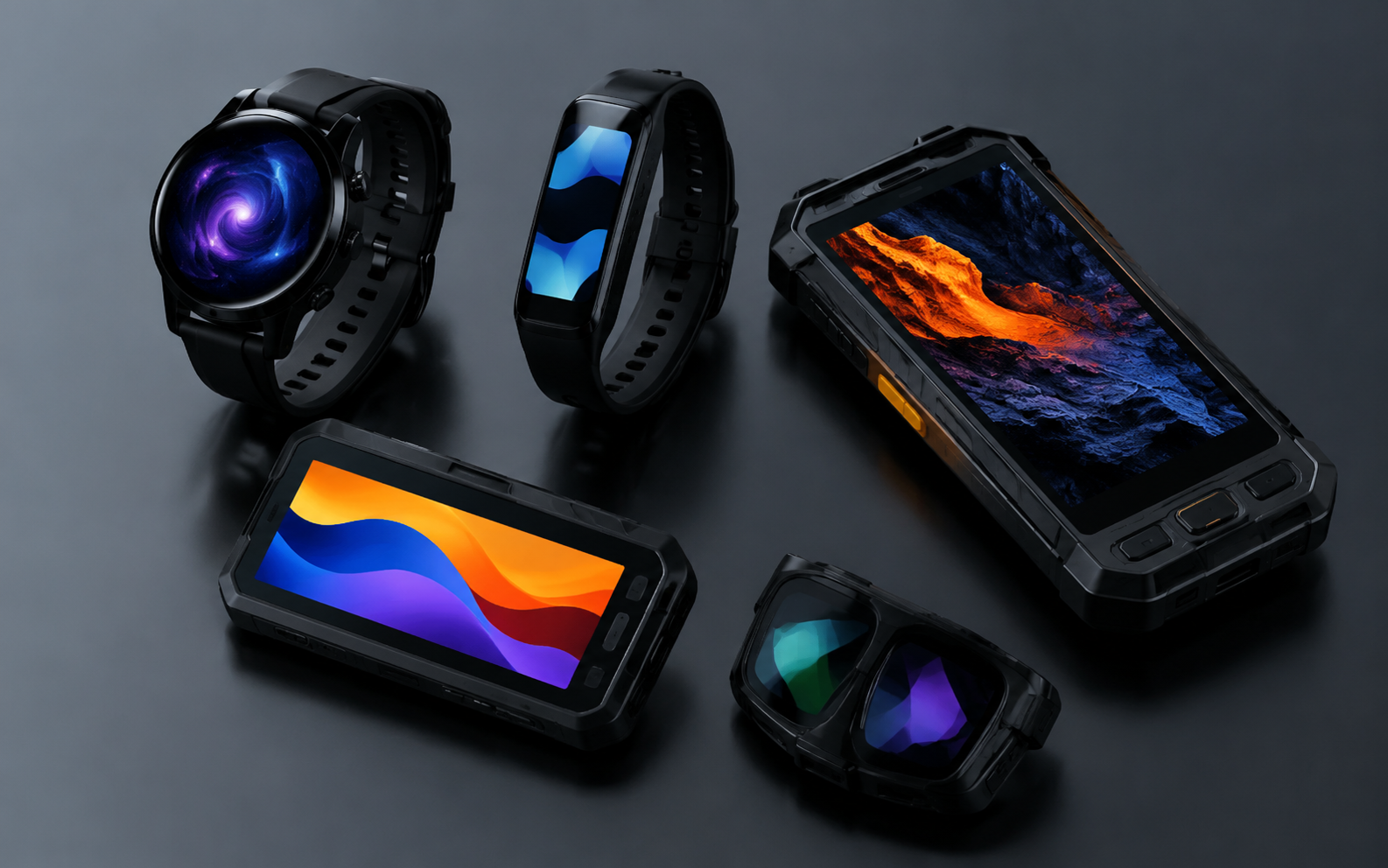
AMOLED modules are widely used in wearables and handheld devices because they combine high contrast, compact structure, wide viewing performance, and dark-state power advantages. The best specification depends on the product category rather than a universal “highest brightness and highest resolution” target.
Wearable devices such as smartwatches and fitness trackers normally prioritize round or compact rectangular screens, thin stack-up, low system power, touch response, outdoor readability, and good visual quality at close viewing distance. A 1.2-inch to 1.9-inch AMOLED range is common for wrist-based products, but the final choice should be driven by active area, enclosure shape, battery capacity, and user-interface density.
Handheld terminals, portable instruments, field devices, medical handheld equipment, and smart controllers usually require larger rectangular displays. For these products, the selection focus shifts to interface compatibility, readability under the expected lighting condition, cover glass, cleaning resistance, operating temperature, ESD design, and long-term supply planning.
For AR, EVF, or near-eye applications, product teams should distinguish between standard AMOLED modules and Micro OLED / OLEDoS displays. Near-eye systems usually require very high pixel density, low latency, compact optical alignment, and strict mechanical tolerances. These projects should be reviewed separately from standard wearable or handheld AMOLED designs.
- Smartwatch / wristband: prioritize active area, round or slim outline, touch, low power UI design, and outdoor readability.
- Medical handheld device: prioritize readability, cleaning process compatibility, electrical safety integration, operating temperature, and validation documentation.
- Industrial handheld terminal: prioritize interface stability, cover glass, ESD, vibration at device level, and sunlight-readable system design.
- Portable consumer electronics: prioritize color quality, UI smoothness, compact thickness, and cost-controlled supply.
- Near-eye display systems: prioritize pixel density, optical engine compatibility, brightness at the optical path, and thermal behavior.
Requirements such as IP65 protection, drop resistance, cleaning chemicals, and button layout should be treated as device-level requirements. A display module can support the system design, but waterproofing, impact protection, and drop performance are normally achieved by the final product structure, gasket design, cover lens, adhesive, enclosure, and assembly process.
Device Constraints
AMOLED selection is often limited more by device constraints than by the display catalog itself. A technically strong panel can still fail a project if the FPC exits in the wrong direction, the connector is too tall, the cover glass creates glare, or the host processor cannot support the required MIPI lane configuration.
The most important constraints are mechanical stack-up, active-area alignment, FPC bend radius, connector placement, supply voltage, interface bandwidth, display initialization, power sequencing, touch controller compatibility, operating temperature, and the battery-life target.
For a wearable product, every fraction of a millimeter matters. The display, touch layer, cover lens, adhesive, foam, bracket, gasket, and enclosure lip all compete for the same limited z-height. For a handheld terminal, the mechanical budget may be more relaxed, but the design may require stronger cover glass, optical bonding, larger battery capacity, or more robust FPC strain relief.
Power planning should not use one generic AMOLED formula. AMOLED power changes with average picture level, brightness setting, refresh rate, color content, driver IC mode, and temperature. A dark UI with a small lit area can draw much less display power than a full-white test pattern at high brightness. For this reason, the power budget should be measured under defined UI patterns rather than estimated from diagonal size alone.
A practical AMOLED design review should answer these questions before sample approval:
- What are the exact active area, panel outline, and module thickness limits?
- Does the host processor support the required MIPI, SPI, MCU, or RGB interface?
- Is the driver IC supported by available initialization code and timing documentation?
- Is touch required, and if yes, is the touch controller compatible with the system I²C/SPI resources?
- What is the maximum cover glass thickness, and is glove or wet touch required?
- Will the product be used indoors, outdoors, in sunlight, or in low-temperature environments?
- What are the target brightness, refresh rate, and battery-life assumptions?
- What are the acceptance criteria for pixel defects, luminance uniformity, color, and appearance?
Display Options
Touch Type
Touch integration should be selected according to the product structure, not only according to cost. AMOLED modules may be display-only, capacitive-touch modules, on-cell touch modules, or display modules paired with a custom cover lens and external touch solution.
Out-cell touch uses a separate touch sensor above the display. It can be flexible for customized cover glass and replacement strategy, but it may increase thickness and require careful optical design. On-cell touch integrates the touch sensor closer to the display stack and can help reduce thickness, but it requires closer review of touch controller, cover glass, noise immunity, and firmware tuning. In-cell touch is commonly associated with highly integrated mobile display systems and may not be available for every custom industrial or wearable project.
DisplayModule product examples show that touch implementation differs by model. The 1.39-inch round AMOLED module integrates capacitive touch and supports MIPI/SPI interfaces. The 3.92-inch AMOLED module lists integrated on-cell touch with FT3519 and I²C interface. A 2.4-inch display project may focus first on the display interface and driver IC, then add touch and cover glass according to the device design.
| Touch Approach | Typical Benefit | Main Design Risk | Best-Fit Use Case |
|---|---|---|---|
| Display-only | Lower stack complexity | External buttons or separate input method required | Indicators, meters, simple handheld equipment |
| Capacitive touch module | Fast integration and familiar UI | Cover glass thickness, ESD, wet touch, and noise tuning | Wearables, portable controls, consumer electronics |
| On-cell touch | Thin structure and integrated touch layer | Controller compatibility and firmware tuning | High-resolution compact handheld devices |
| Custom cover lens + touch | Better mechanical and brand design flexibility | Optical bonding, adhesive selection, and tolerance control | Industrial terminals, medical handhelds, outdoor devices |
Important touch parameters include touch controller model, report rate, I²C/SPI address, ESD target, cover glass thickness, glove touch, wet touch, palm rejection, active touch area, and mechanical alignment. These details should be confirmed before EVT or prototype tooling.
Brightness Requirements
Brightness should be selected according to the real use environment. A module that is bright enough indoors may not be readable under strong outdoor light, while excessive brightness can increase power consumption and shorten usable battery life if it is sustained for long periods.
Official module specifications should be used rather than generic AMOLED claims. For example, a 1.39-inch round AMOLED module lists 350 cd/m² typical luminance. A 3.92-inch AMOLED module lists 500 cd/m² typical luminance in white mode. These values are module-specific; they should not be used as a universal brightness promise for all AMOLED products.
Readability is not only a nit number. It also depends on cover glass reflectance, air gap, optical bonding, anti-glare treatment, anti-reflective coating, UI contrast, font size, viewing angle, ambient light sensor logic, and thermal limits. For outdoor products, a moderate-brightness display with good optical bonding and low-reflection cover glass may read better than a higher-brightness display behind reflective glass.
AMOLED optical and electro-optical measurements should be performed under defined conditions. IEC 62341-6-1 specifies measurement conditions and methods for optical and electro-optical parameters of OLED displays. For engineering review, record the test pattern, luminance level, ambient condition, measurement distance, viewing angle, refresh rate, and warm-up condition.
- Indoor UI: confirm typical luminance, contrast, color, viewing angle, and low-brightness comfort.
- Bright indoor / shaded outdoor: test readability with actual cover glass and final UI colors.
- Direct outdoor use: evaluate brightness, optical bonding, reflection, heat, and battery impact together.
- Night mode: confirm minimum brightness, dimming method, color shift, and user comfort.
- Always-on display: test static content, burn-in risk, and power under the real AOD layout.
A safe specification should define typical luminance, peak luminance if applicable, measurement method, allowed tolerance, and whether the value is measured before or after cover lens and bonding. Avoid writing a fixed brightness requirement such as “all outdoor products require 2,000 nits” unless that number has been validated for the specific optical stack and use case.
Power Consumption
AMOLED power behavior is different from LCD power behavior. Since AMOLED pixels are self-emissive, dark pixels consume little or no light-emission power, while bright full-screen content increases current. LCD modules usually require a backlight, so their power profile does not follow the same lit-pixel behavior.
For battery-powered devices, power should be measured with several defined patterns: black screen, low-brightness UI, typical UI, full-white screen, video or animation, and always-on display mode. The measurement should also record brightness, refresh rate, supply voltage, temperature, touch status, and sleep mode configuration.
Three design levers are especially important:
- UI color strategy: dark themes and small lit areas can reduce AMOLED display power compared with full-white layouts.
- Refresh-rate strategy: static screens, AOD pages, and simple dashboards may not require high refresh rates all the time.
- Driver IC modes: sleep, partial update, low-power mode, and brightness control should be verified in firmware.
Power optimization should not be described with a single pixel-current value because current changes by material, brightness, color, temperature, driver IC, and content. A better engineering practice is to define a power test table and measure the selected module under real UI conditions.
| Power Test Scene | What to Record | Why It Matters |
|---|---|---|
| Black screen | Panel supply current, driver IC state, leakage behavior | Checks baseline and standby behavior |
| Typical UI | Average current at target brightness | Represents normal battery-life calculation |
| Full-white screen | Peak current and temperature rise | Defines worst-case design margin |
| AOD layout | Current with small lit area and low refresh | Important for watch and standby products |
| Outdoor brightness mode | Current, luminance, thermal behavior, duration limit | Prevents battery and lifetime surprises |
Factory Support
Sample Testing
Sample testing is the bridge between a display that works on the bench and a display that can be released into a product. The goal is not only to turn the screen on, but to confirm optical performance, electrical stability, mechanical fit, firmware compatibility, touch behavior, reliability risk, and acceptance criteria.
For AMOLED modules, optical and electro-optical testing should include luminance, uniformity, chromaticity, contrast, viewing angle, response behavior if required, and power consumption under defined patterns. IEC 62341-6-1 is a relevant OLED measurement reference for optical and electro-optical parameters. Image sticking and lifetime evaluation should be considered for static UI, always-on display, and high-brightness products; IEC 62341-5-3 specifies measurement methods for image sticking and lifetime of OLED display panels and modules.
Pixel defects should not be described as “no bright or dark spots” unless the commercial agreement and inspection class explicitly require that level. In display supply, pixel defects are commonly controlled by an agreed defect class or customer acceptance standard. ISO 9241-307 is often referenced for pixel defect classes, and the exact class should be defined in the purchase specification or quality agreement.
- Visual inspection: scratches, cracks, stains, foreign material, mura, polarizer defects, and cover glass defects.
- Mechanical inspection: active area, panel outline, thickness, FPC length, connector, and alignment tolerance.
- Optical inspection: luminance, uniformity, color point, contrast, viewing angle, and black-state appearance.
- Electrical inspection: supply voltage, current, display initialization, reset timing, interface stability, and sleep mode.
- Touch inspection: report rate, accuracy, edge performance, multi-touch behavior, ESD impact, glove or wet touch if required.
- Reliability review: temperature range, humidity exposure, thermal cycling, static-image risk, FPC bend, and connector durability.
Sample approval should include both the display supplier and the customer engineering team. The customer should test the module inside the real enclosure, with the real cover glass, final FPC bend path, production host board, real firmware, and representative UI content. Many display issues only appear after the optical stack and final electronics are combined.
Customization Process
DisplayModule supports off-the-shelf modules for quick evaluation as well as OEM customization such as FPC shape modification, cover glass changes, display integration, and driver-board development. The website also states that DisplayModule works with NexPCB to support broader development and mass production needs.
A reliable AMOLED customization process should be organized around documented deliverables rather than informal verbal requirements. Typical deliverables include the requirement sheet, recommended module list, mechanical drawing, electrical interface review, driver IC documentation, power sequence, sample test report, quality agreement, packaging requirement, and production delivery plan.
Recommended customization flow: requirement review → module selection → mechanical and electrical confirmation → sample purchase or prototype build → firmware bring-up → optical and power validation → reliability review → quality agreement → pilot order → production order.
Lead time should not be stated as a fixed number for all products. DisplayModule’s public FAQ states that bulk lead time depends on model and quantity. Some product pages list sample purchase availability and factory bulk lead time for that specific model, but those values should not be generalized across all AMOLED projects.
For a faster and more accurate quotation, prepare the following information:
- Target product type and expected annual quantity
- Display size, active area, resolution, and preferred module shape
- Mechanical drawing or maximum outline size
- Required interface: MIPI, SPI, MCU, RGB, or other
- Host processor or main board information
- Touch requirement, cover lens, bonding, and surface treatment
- Brightness target and use environment
- Operating temperature, storage temperature, and reliability requirements
- Required documentation, inspection standard, and packaging requirement
Custom display projects should avoid changing core requirements after sample approval. Changes to active area, FPC routing, connector position, cover glass, touch controller, or driver IC may require new drawings, new samples, firmware changes, or additional validation.
Mass Production
The mass production stage should convert the verified sample design into a stable supply process. For AMOLED modules, production planning should cover incoming material control, COG bonding, FPC integration, optical and electrical QA, appearance inspection, packaging, traceability, and customer acceptance criteria.
DisplayModule publicly describes its capability as including Chip-on-Glass bonding, automated FPC integration lines, ISO Class cleanroom environment, micron-level COG and FPC assembly, and 100% optical and electrical QA. These are appropriate statements to use because they are supported by the company website. Avoid unsupported claims such as a specific city factory location, fixed yield target, fixed MOQ, fixed payment term, or fixed 5,000-unit lead time unless those terms are confirmed for the specific order.
Mass production planning should define the quality standard before the order is placed. The quality agreement should specify pixel defect class, visual inspection conditions, luminance tolerance, color tolerance, mechanical tolerances, FPC handling rules, packaging method, barcode or lot traceability, sampling plan, and failure-analysis process.
- MOQ and pricing: confirm by model, customization scope, and order quantity.
- Lead time: confirm by model, quantity, material availability, and customization requirement.
- Yield and defects: define by agreed inspection standard, not by a universal marketing number.
- Pixel defects: define allowed bright, dark, and sub-pixel defects by agreed class or customer standard.
- Packaging: define ESD protection, tray or reel method, label content, humidity control, and carton requirements.
- Traceability: keep lot, date code, inspection record, and failure-analysis path for production support.
A production-ready AMOLED project should have a locked drawing, approved sample, confirmed BOM, validated driver code, defined power sequence, approved cover glass or touch stack, signed quality criteria, and a clear communication path for engineering changes. This is more reliable than relying on general claims about yield, delivery speed, or one-size-fits-all specifications.
For wearable and handheld products, the strongest AMOLED design is usually not the brightest or thinnest module in the catalog. It is the module whose active area, interface, touch structure, power behavior, optical performance, mechanical stack, documentation, and supply plan match the product requirements from the beginning.
Weiterlesen
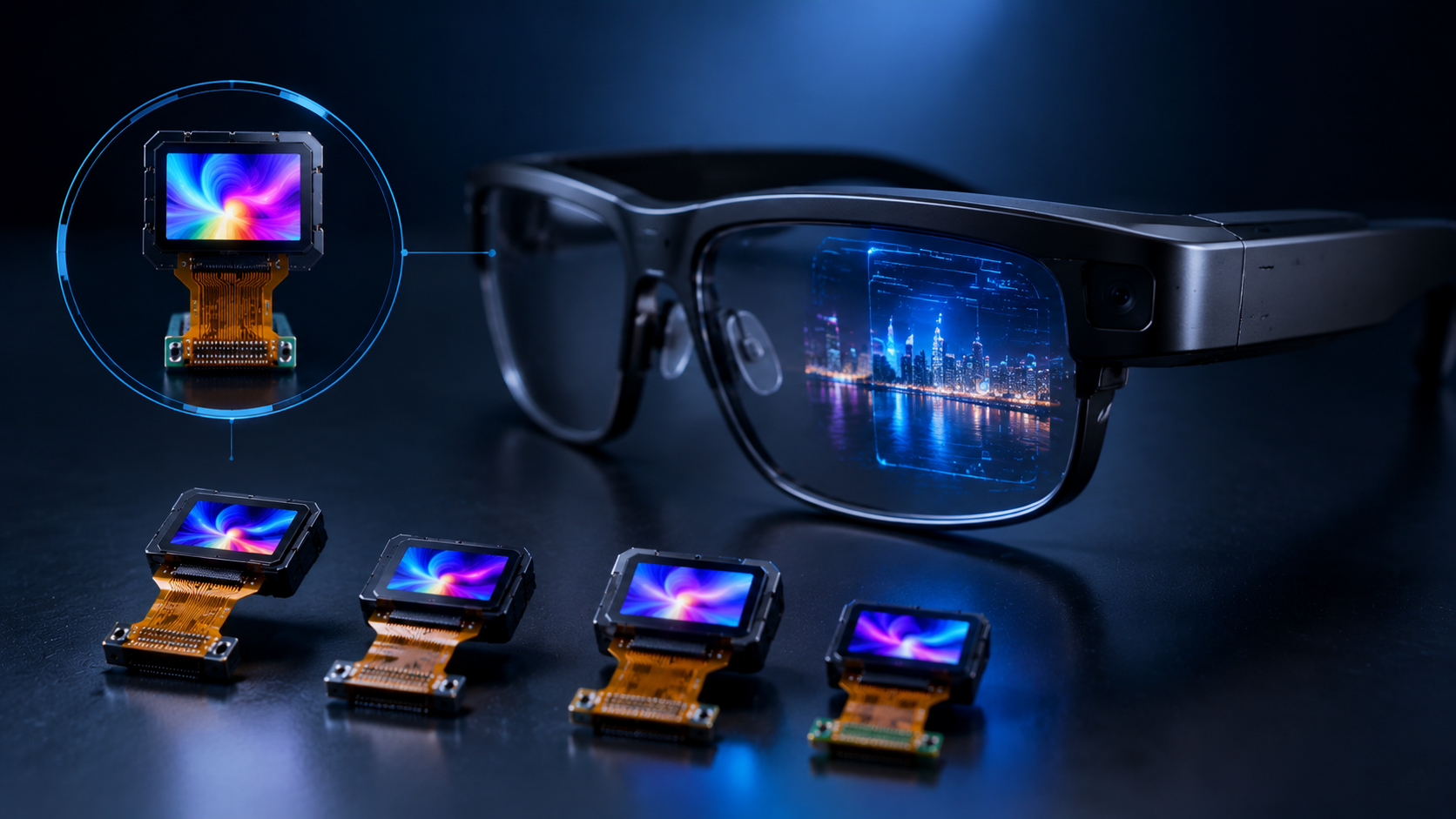
Micro OLED, also known as OLED-on-silicon or OLEDoS, is a high-density microdisplay technology used in electronic viewfinders, wearable display glasses, AR/VR optical engines, scopes and other c...
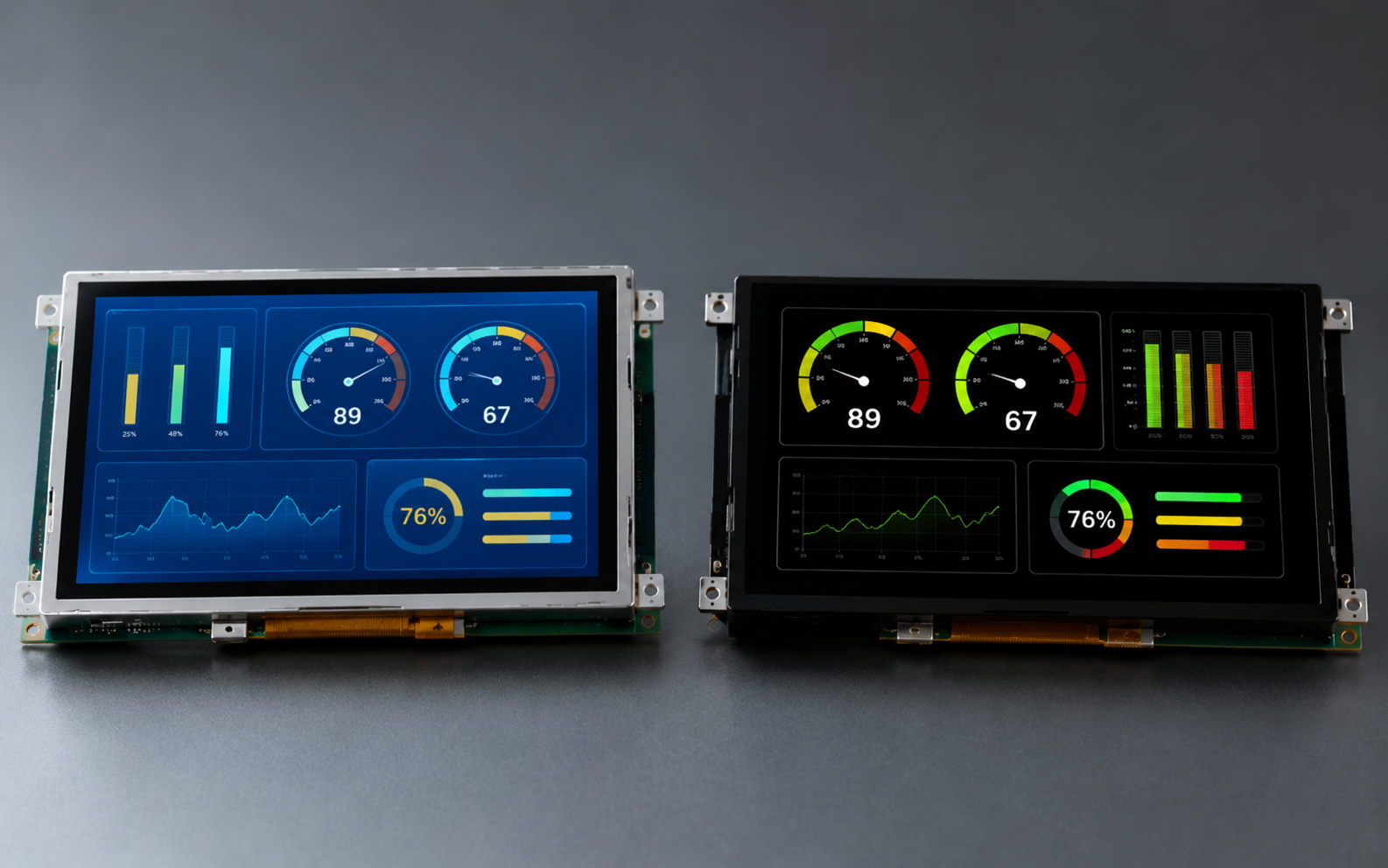
In industrial control panels, instruments, HMI devices, portable testing equipment, and smart terminals, both TFT LCD and OLED are common display options. Neither technology is universally better. ...
Hinterlasse einen Kommentar
Diese Website ist durch hCaptcha geschützt und es gelten die allgemeinen Geschäftsbedingungen und Datenschutzbestimmungen von hCaptcha.