


Custom Micro OLED Modules for AR Glasses | Brightness, Size, Power and Validation
Micro OLED, also known as OLED-on-silicon or OLEDoS, is widely used in compact AR and VR optical engines because it combines self-emissive contrast, high pixel density and a small active display area. Public commercial examples include compact FHD panels around 0.44 inch with pixel pitch near 5 μm, as well as larger high-resolution panels used in VR and mixed reality systems. Peak luminance varies significantly by model, color architecture, drive duty, thermal design and lifetime target, so panel brightness should not be treated as the same number as eye-side brightness after the optics.

What It Is
Module Basics
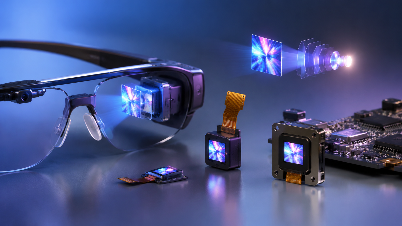
A Micro OLED module uses an OLED emitting stack integrated with a silicon backplane, rather than the larger glass backplanes used in conventional mobile OLED panels. The silicon backplane enables very small pixel pitches, high pixel density and integrated drive circuitry, making it suitable for near-eye displays where the image must be magnified by an optical system.
For AR glasses, the most important specification is not a single headline number. A useful module evaluation should separate panel-level luminance, optical-engine throughput, eye-side luminance, power consumption, thermal derating and lifetime. A module that performs well in a lab at short duty cycles may not deliver the same brightness when operated continuously inside a thin glasses temple or coupled into a waveguide.
- Substrate and backplane: OLED-on-silicon modules typically use a CMOS or single-crystal silicon backplane.
- Pixel density: Commercial OLED microdisplays commonly reach several thousand pixels per inch, with recent public examples around 4,000–5,000 ppi.
- Pixel pitch: Recent AR-oriented products can be around 5 μm pixel pitch; exact values depend on the supplier, resolution and panel size.
- Contrast: OLED microdisplays can achieve very high native contrast because black pixels emit little or no light, but system contrast also depends on optics, ambient light leakage and waveguide design.
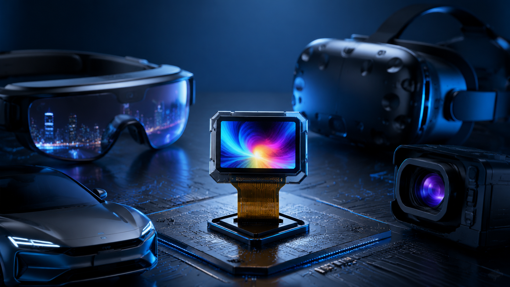
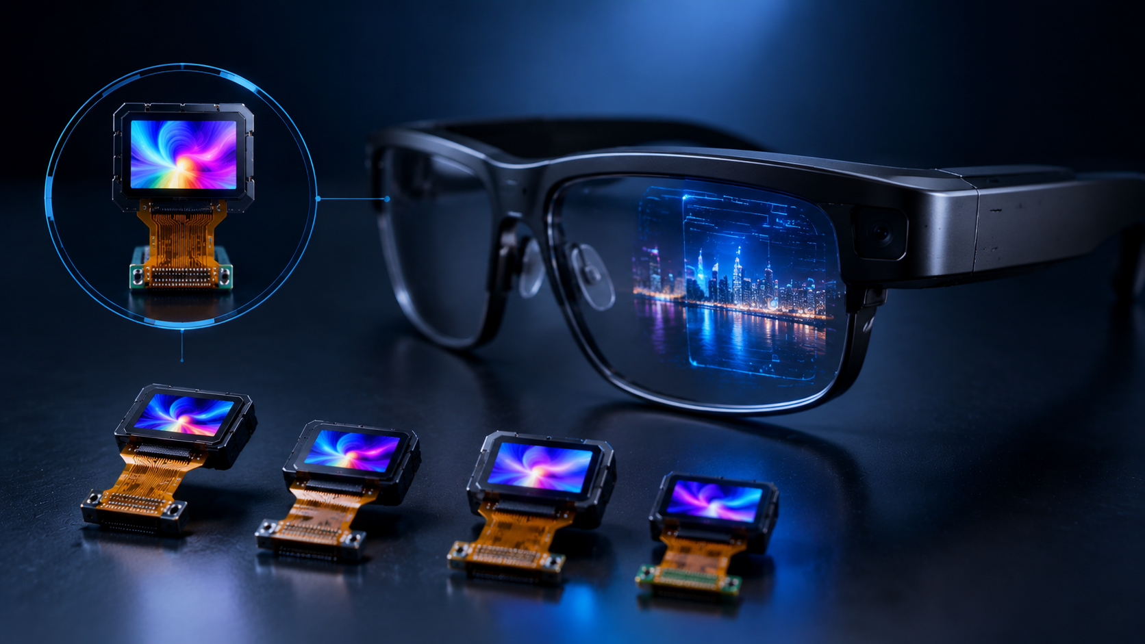
- Display sizes: AR and VR microdisplays commonly appear in the 0.4–1.3 inch class, selected according to field of view, resolution, optical architecture and industrial design constraints.
- Power: Power consumption is content-, brightness-, frame-rate- and driver-dependent. It should be measured at the intended average picture level, duty cycle and operating temperature.
AR Use Cases
AR glasses create a difficult three-way trade-off: outdoor readability requires high luminance, all-day comfort requires low power and low heat, and consumer-style industrial design requires a compact optical engine. No single Micro OLED specification optimizes all three at the same time. Selection should therefore begin with the use case, not with the highest available brightness figure.
| Scene | Priority | Key Requirement | Suitable Micro OLED Direction |
|---|---|---|---|
| Outdoor navigation / field maintenance | Brightness and thermal stability | Readable virtual image under bright ambient conditions | High-luminance OLED-on-silicon module; verify sustained panel luminance and measured eye-side luminance through the actual optics |
| Indoor warehouse picking / logistics | Power endurance | Long operating time with simple graphics and moderate brightness | Compact FHD-class module with adaptive dimming, low average picture level and validated thermal headroom |
| Training, gaming or immersive visualization | Resolution and refresh rate | High pixel density, high frame rate and low motion blur | Larger high-resolution module or dual-display architecture; confirm optical magnification, field of view and frame-rate support |
| Low-light inspection or night operation | Black level and contrast | Low light leakage and clear overlays in dark scenes | OLED microdisplay with validated black level, low mura and controlled minimum luminance |
User Pain Points
Engineering teams most often encounter three problems during Micro OLED selection: confusing peak brightness with sustained brightness, underestimating optical losses after waveguide coupling, and discovering thermal derating too late in the mechanical design cycle.
Always ask for both panel-level luminance and system-level eye-side luminance. The useful AR brightness is the brightness delivered to the eye after relay optics, polarization losses, in-coupling, pupil expansion and out-coupling, not just the number printed in the display datasheet.
Datasheets may report peak luminance under specified duty ratio, temperature and measurement geometry. In a real AR waveguide system, only a fraction of the emitted light reaches the eye. The fraction depends on relay optics, coatings, polarization, waveguide material, grating efficiency, eyebox expansion and the target field of view. For this reason, a supplier quotation should include the exact drive condition, duty ratio, test temperature and measurement point.
Key Performance
High Brightness
High brightness is one of the most important specifications for AR glasses, but it is also one of the easiest to misread. The same panel can show different luminance under short-pulse drive, continuous drive, different average picture levels and different thermal conditions. For product design, sustained brightness at the target operating temperature is more useful than an isolated peak value.
Do not compare brightness values unless the drive duty, frame rate, temperature, color point, average picture level and measurement location are known. Peak luminance, sustained luminance and eye-side luminance are different specifications.
| Technology | Brightness Characteristic | AR Suitability | Key Limitation |
|---|---|---|---|
| Micro OLED / OLED-on-silicon | Commercial products can range from roughly 1,000 cd/m² to 10,000 cd/m² depending on model and drive condition | Strong fit for compact near-eye systems requiring high pixel density and high contrast | Thermal management, lifetime at high luminance and optical throughput |
| LCOS | Depends heavily on the external LED or laser illumination system | Useful where brightness and optical architecture can justify a larger illumination path | Polarization loss, illumination volume and lower native black level than OLED |
| DLP | Can support high brightness with suitable illumination | Useful in some industrial and projection-style AR systems | Optical-engine size, power and mechanical integration |
| MicroLED | Potentially very high brightness | Promising for outdoor AR, especially waveguide systems | Full-color integration, yield, cost and availability at consumer scale |
Compact Size
Compact size is critical because AR glasses must fit display, optics, battery, processor, sensors and thermal structures into a lightweight frame. A smaller Micro OLED panel can reduce optical-engine volume, but the final module thickness also depends on the driver board, FPC routing, cover glass, relay lens, heat spreader and waveguide coupling structure.
Size reduction can introduce new risks. Dense routing can increase EMI sensitivity, the available thermal path becomes smaller, and mechanical tolerance becomes harder to control. For this reason, the module should be evaluated as part of the complete optical engine rather than as a loose display panel.
| Display Class | Common Use Direction | Benefit | Integration Risk |
|---|---|---|---|
| 0.4–0.55 inch | Compact AR glasses and lightweight monocular/binocular engines | Small active area and easier industrial-design packaging | Demanding optics, high magnification and tight thermal path |
| 0.6–0.75 inch | Higher aperture AR optical engines and development platforms | More active area for optical coupling and resolution options | Larger engine volume and higher thermal load |
| 1.0 inch and above | VR, MR, industrial viewers or projector-style architectures | Higher resolution options and easier optical magnification | Less suitable for ultra-thin consumer glasses |
Low Power Use
Power consumption is a system-level constraint. A 1,000 mAh battery at 3.7 V stores about 3.7 Wh before conversion and usability losses. If a product targets 8 hours of operation, the average power budget for the entire device must be managed carefully across display, processor, wireless, sensors, audio and standby functions. The display engine often needs to stay well below the total device average, especially for all-day wearable modes.
- Measure at the intended content: OLED power depends on average picture level. A mostly black UI can consume much less power than a full-white test pattern.
- Separate panel and system power: Include display panel, driver IC, bridge board, sensors, illumination support if any, and thermal control overhead.
- Use adaptive brightness: Ambient-light-based dimming and UI design can reduce average power without reducing perceived readability.
- Validate flicker and artifacts: PWM or pulsed drive can help power and thermal control, but must be checked for flicker, camera banding and motion artifacts.
- Check thermal derating: Sustained high brightness may reduce lifetime or trigger derating, especially inside sealed or low-airflow glasses temples.
How To Choose
Optics Match
Optical matching is often more important than the display panel specification alone. A Micro OLED panel emits over a wide angular distribution, while a waveguide or relay optical system accepts only a limited cone of light. The design must therefore manage numerical aperture, etendue, polarization, color spectrum, pupil expansion and mechanical tolerance.
For waveguide-based AR glasses, engineers should estimate the full optical throughput from the display plane to the eye. This includes relay-lens transmission, aperture clipping, polarization effects, in-coupler efficiency, propagation loss, out-coupler efficiency and eyebox expansion. The final acceptance metric should be measured at the eyebox whenever possible.
- Collect panel-level data: active area, resolution, pixel pitch, luminance, contrast, color coordinates, spectrum, angular emission and drive conditions.
- Confirm optical input requirements: numerical aperture, angular acceptance, polarization state, chief-ray angle and mechanical alignment tolerance.
- Estimate throughput from panel to eye, including relay optics, waveguide coupling and pupil expansion.
- Measure eye-side luminance, uniformity, color shift and contrast using near-eye display measurement conditions appropriate for AR eyewear.
- Repeat measurements at high and low operating temperatures to check thermal drift, luminance derating and color stability.
Custom Options
Standard Micro OLED modules may be sufficient for prototypes, but production AR products often need customization. The highest-impact customizations are usually luminance/color binning, custom drive settings, optical interface treatment, FPC layout, EMI shielding and thermal/mechanical interfaces.
For binocular AR glasses, left-right matching is especially important. Even when two panels come from the same supplier, the system should still verify luminance, white point, gamma curve and color uniformity for each eye. Per-eye calibration through driver registers or the application processor can reduce visible mismatch.
For binocular systems, define acceptance limits for luminance difference, white-point difference, gamma tracking and uniformity before mass production. Do not rely only on the supplier's batch label.
| Customization | Impact on AR System | Planning Note | What to Verify |
|---|---|---|---|
| Color and luminance binning | Reduces visible mismatch between left and right eye | Usually requires supplier-side sorting and extra incoming inspection | White point, luminance, gamma and uniformity per eye |
| Custom driver firmware, gamma or LUT | Optimizes brightness, power, color and thermal behavior | Requires clear test patterns and acceptance criteria | Frame rate, flicker, grayscale tracking and thermal derating |
| Optical bonding or cover-glass treatment | Can reduce reflection and improve coupling stability | Must be validated for reliability and rework process | Transmission, haze, reflection, delamination and stress birefringence |
| FPC, connector and EMI shielding | Improves packaging inside thin glasses temples | Should be co-designed with the mechanical stack | Signal integrity, EMI, bend radius and assembly yield |
| Thermal interface design | Improves sustained brightness and lifetime margin | Requires system-level thermal simulation and measurement | Panel temperature, driver IC temperature and user-touch temperature |
Testing Tips
Supplier datasheets are useful, but they rarely replace system-level qualification. AR glasses place the display module near the user's face, inside a compact mechanical envelope, and often behind waveguide or relay optics. The qualification plan should therefore combine display tests, optical-engine tests, environmental tests and user-safety constraints.
For image-quality measurement, use near-eye display methods suitable for AR eyewear, including eyebox position, eye-side luminance, image uniformity, color shift and see-through characteristics. For environmental reliability, damp heat, thermal cycling, high-temperature operation, mechanical shock and flex testing should be selected according to the final product environment and the supplier's rated conditions.
- Initial optical characterization: Measure panel luminance, eye-side luminance, contrast, color coordinates, color temperature, uniformity and angular behavior before stress testing.
- Thermal operation test: Run the module at the intended brightness, frame rate and UI average picture level inside the real mechanical enclosure. Record panel temperature, driver temperature and brightness derating over time.
- Damp heat and humidity exposure: Use an agreed standard such as IEC 60068-2-78 or a supplier-approved equivalent. The test condition should match the module's material limits and final product risk profile.
- Humidity bias for electronics: For driver boards or non-hermetic IC packages, consider JEDEC-style temperature-humidity-bias testing where applicable.
- Mechanical shock and drop: Use board-level and product-level drop or shock tests according to the final product category. Do not treat component-level drop testing as a full replacement for finished-device testing.
- Flex and hinge cycling: Test FPC routing, connector retention and optical bonding under repeated temple opening, closing and torsion.
- Image retention and burn-in: Test static UI elements, high-brightness icons and high-contrast overlays under realistic operating profiles.
- Post-stress remeasurement: Repeat luminance, color, contrast, uniformity and pixel-defect inspection after every major stress sequence.
For Micro OLED module selection in AR glasses, use four decision gates: panel capability, optical-engine throughput, thermal/power headroom and reliability evidence. A high peak-brightness number is useful only when it is tied to drive condition, temperature, lifetime target and measured eye-side performance.
Weiterlesen
Micro OLED displays, also known as OLED-on-Silicon displays, combine high pixel density, fast response, high contrast, compact size, and efficient power performance under suitable drive condition...
Micro OLED, also known as OLED-on-silicon or OLEDoS, is a high-density microdisplay technology used in electronic viewfinders, wearable display glasses, AR/VR optical engines, scopes and other c...
Hinterlasse einen Kommentar
Diese Website ist durch hCaptcha geschützt und es gelten die allgemeinen Geschäftsbedingungen und Datenschutzbestimmungen von hCaptcha.