


High Brightness LCD Panels | Heat Dissipation, Nits Level & Power Draw
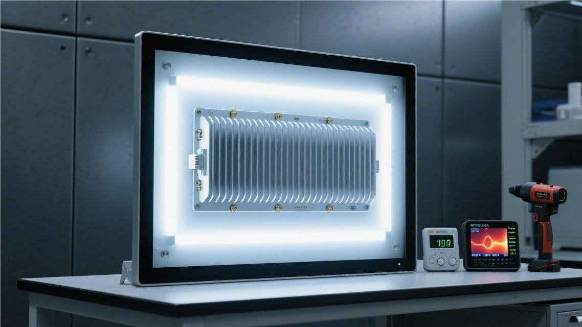
High-brightness LCD panels often reach a brightness of 2500 nits. Since a 55-inch panel consumes approximately 250W, it requires an aluminum substrate and forced convection cooling via fans.
During operation, the backlight current should be limited to within 85% of its rated value, and a chassis heat dissipation gap of 5 cm must be ensured to prevent black screen failures caused by heat accumulation.
Heat Dissipation
When high-brightness LCD panels output 2500–5000 nits, the heat converted by the backlight module accounts for more than 80% of the total power consumption.
If the LED Junction Temperature exceeds 85°C, the luminous efficacy decreases by approximately 3%-5% for every 10°C rise in temperature.
The thermal architecture must be able to control the liquid crystal layer temperature below the critical threshold of 70°C under an ambient temperature of 40°C accompanied by a solar radiation heat load of 1100W/m², preventing isotropic black spots.
Heat Source Distribution
When a high-brightness LCD panel outputs 3000 nits, the overall power consumption of a 55-inch device is typically between 250W and 350W. The electrical energy conversion process is accompanied by intense energy loss, with the current physical upper limit of photoelectric efficiency remaining at around 25%. The remaining 75% of input electrical energy is entirely converted into pure thermal energy accumulation within the enclosed chassis.
Light-emitting diode (LED) arrays account for the vast majority of global heat sources, and their heating mechanism is closely related to the packaging architecture. Between 1000 and 3000 high-power SMD packaged lamp beads are densely arranged on the bottom edges or the back. When a forward voltage (Vf) of 3.0V to 3.2V is applied, the operating current of a single lamp bead can soar to 150mA or higher.
Semiconductor P-N junctions generate a large number of phonons during non-radiative recombination. Lattice vibrations at the microscopic level manifest macroscopically as a rapid increase in temperature. Once the LED junction temperature exceeds the physical boundary of 85°C, the quantum yield of the phosphor will drop exponentially.
Heat accumulation in the backlight module is restricted by multiple electrical and physical factors:
- Forward current overload heating
- Non-radiative recombination loss at the P-N junction
- Photothermal changes in the phosphor layer
- Substrate thermal impedance bottlenecks
When light leaves the Light Guide Plate (LGP) and penetrates upward through the optical film stack, it encounters a secondary thermal evolution. The inherent optical transmittance of liquid crystal display panels is extremely low, usually only 5% to 7% of the backlight can actually penetrate the front polarizer to reach the human eye.
Up to 93% of high-intensity photons are physically absorbed by the bottom polarizer, color filters, and the liquid crystal molecule layer itself. The polyethylene terephthalate (PET) substrate at the bottom of the polarizer has an absorption rate of about 18% for the blue light band, and the absorbed light energy is converted into heat on the spot.
The TFT array layer contains cross-densely packed Indium Tin Oxide (ITO) transparent conductive circuits. The ITO impedance value is 50 to 100 ohms/square, and high-frequency addressing pulses passing through will generate microampere-level leakage current and Joule heat.
Red and green pigments in color filters have strong absorption characteristics for short-wave blue light. When the 450nm blue light emitted by the backlight passes through the filter, the light intensity attenuates by more than 60%, and the attenuated portion completely turns into a photothermal effect.
In an outdoor environment with 100,000 lux of intense sunlight, the LCD glass substrate surface simultaneously withstands dual heating from internal photon absorption and external infrared radiation. The thermal conductivity of the glass substrate is only about 1.0 W/m·K, making it very easy for heat to accumulate locally in the liquid crystal layer.
The Power Supply Unit (PSU), as a secondary heat source, is responsible for converting 110V/220V AC power into multiple low-voltage DC outputs. The peak energy transfer efficiency of industrial-grade switching power supplies generally fluctuates between 88% and 92%.
Taking a high-brightness display running at a full load of 300W as an example, 24W to 36W of electrical energy will dissipate in the form of heat on the power board. Heat is highly concentrated on the surfaces of active power devices and magnetic components.
Switching transistors (MOSFETs) generate high temperatures due to conduction resistance (Rds(on)) and switching losses during tens of thousands of high-speed opening and closing actions per second. Under high-load conditions, the surface temperature of MOSFETs is maintained at 70°C to 80°C year-round.
Local hotspots inside the power board are distributed across the following components:
- Switching transistors (MOSFETs)
- Main transformer cores and coils
- Large-capacity aluminum electrolytic capacitors
- Rectifier bridges and diodes
The ferrite core of the main transformer generates significant hysteresis and eddy current losses in an alternating magnetic field of 50kHz to 100kHz. The Direct Current Resistance (DCR) of copper wire windings increases by about 3.9% for every 10°C rise in temperature.
The increase in resistance leads to a positive feedback loop of copper loss (I²R) heating. Large-capacity electrolytic capacitors adjacent to the transformer are extremely sensitive to high temperatures; for every 10°C rise in ambient temperature, the evaporation rate of the internal electrolyte doubles, and the lifespan is reduced by 50%.
The Timing Control board (T-CON) and Source/Gate addressing ICs also cannot be ignored when processing massive video data streams. Under 4K resolution combined with 60Hz or 120Hz refresh rates, the microprocessor needs to execute billions of operations per second.
The flipping actions of millions of TFT transistors require the source control chip to provide continuous and precise analog voltages. Control ICs using COF (Chip on Film) flexible packaging technology are closely attached to the panel edge glass, resulting in extremely high operating current density.
Although the power consumption of a single addressing chip is only 1.5W to 2.5W, the heat dissipation area is usually less than 0.5 square centimeters. Local heat flux density can even far exceed that of the backlight module area, appearing as obvious narrow-band high-temperature red zones under a thermal imager.
A 55-inch 4K panel edge usually has 12 to 16 Source ICs attached. Each chip integrates up to 960 output channels, with a synchronous switching frequency reaching 150MHz.
The polyimide (PI) flexible film at the bottom of the chip has extremely poor thermal conductivity, only 0.12 W/m·K. If additional thermal silicone pads are not added, heat will flow back into the liquid crystal cell along the glass substrate.
Thermal Technology Comparison
In semi-outdoor environments with brightness below 1500 nits, passive cooling with an aluminum backplane is the standard architectural choice. The thermal conductivity of aluminum alloy 6061 is approximately 167 W/m·K. Thermal capacity is improved by increasing the backplane thickness to 2.5mm to 3.0mm. This solution relies entirely on natural convection, and the temperature difference (ΔT) between the panel interior and the environment is usually maintained between 20°C and 25°C.
When brightness requirements cross the 2500 nits threshold, the surface area limitations of passive cooling lead to heat accumulation. At this point, Heat Pipe technology is introduced, utilizing the phase change process of pure water or ethanol within a vacuum. The equivalent thermal conductivity of a heat pipe can soar to over 10,000 W/m·K, which is dozens of times that of pure copper (385 W/m·K).
Heat pipes use sintered capillary structures with diameters of 6mm or 8mm to quickly migrate heat from the LED backlight module to heat dissipation fin areas far from the liquid crystal layer. The maximum heat transfer capacity (Qmax) of a single 6mm heat pipe is approximately 35W to 50W. On the back of a 55-inch high-brightness panel, 4 to 6 heat pipes are usually arranged in a cross pattern to cover heat points.
The following is a physical parameter comparison of three mainstream passive and semi-active heat dissipation media:
| Thermal Physical Medium | Thermal Conductivity (W/m·K) | Thermal Impedance (℃·cm²/W) | Max Operating Temp (℃) |
|---|---|---|---|
| Conductive Aluminum Plate (Al 6061) | 167 | 0.85 | 150 |
| Nano-Carbon Coating (Carbon) | 300 - 600 | 0.45 | 200 |
| Copper Heat Pipe (Heat Pipe) | 10,000+ (Equivalent) | 0.05 | 120 |
This heat migration logic faces severe challenges in 4000 nits full-outdoor devices, as ambient temperatures of 45°C render passive cooling ineffective. Active Air Cooling systems use ball-bearing fans with speeds up to 3500 RPM for forced convection. The wind pressure generated by the fans must overcome a pressure loss of 50 Pa to 80 Pa caused by air filters.
Air cooling architectures are divided into open-loop and closed-loop cycles. Open-loop cycles directly suck in external air, requiring filter screens with 100-mesh stainless steel weaving precision. Closed-loop cycles rely on internal dual-way Heat Exchangers (HEX), where clean internal air transfers heat to external cold air through a heat exchange core, with heat exchange efficiency (ε) usually between 0.6 and 0.75.
When ambient radiation heat reaches 1120 W/m², single air cooling cannot stop heat from penetrating the liquid crystal layer. Liquid Cooling systems use Micro-channel Cold Plates to directly cover the back of the LED driver substrate. The internal water channel width of the cold plate is only 0.5mm, and the water flow rate is maintained at 1.5 L/min to 2.0 L/min.
The coolant used in liquid cooling systems is mostly an ethylene glycol aqueous solution, which has a specific heat capacity as high as 3.7 kJ/(kg·K). Compared to the 1.005 kJ/(kg·K) specific heat capacity of air, liquid can carry away several times more heat with a smaller temperature rise. Under 5000 nits ultra-high-brightness backlighting, liquid cooling can control the LED junction temperature below 60°C, extending the lifespan to 100,000 hours.
Thermal performance quantification table for different brightness levels and environmental loads:
- 1500 nits Indoor: Natural convection, wind speed < 0.2 m/s, total system thermal resistance > 1.2 ℃/W
- 2500 nits Semi-Outdoor: Powerful fans, wind speed 2.5 m/s, total system thermal resistance 0.6 - 0.8 ℃/W
- 4000 nits Full Outdoor: Heat exchanger + high static pressure fan, total system thermal resistance 0.3 - 0.5 ℃/W
- 5000 nits Industrial Area: Liquid cooling/Phase change cooling, total system thermal resistance < 0.2 ℃/W
Between the high-brightness LCD and the protective glass, Optical Clear Resin (OCR) or special silicone oil is filled. This Optical Bonding technology eliminates the air layer, increasing thermal conductivity from 0.026 W/m·K (air) to over 0.15 W/m·K.
Heat is no longer trapped in the LCD glass but is conducted along the optical glue to the outermost layer of protective glass for dissipation. This path can reduce the working temperature of the liquid crystal surface by about 8°C to 12°C. Additionally, the ITO insulation layer coated on the inside of the protective glass can block over 85% of near-infrared rays (780nm-2500nm), significantly reducing external heat input.
To ensure that the cooling solution does not fail under high and low temperature cycles, industrial-grade testing requires continuous 48-hour aging experiments in environmental chambers ranging from -30°C to +70°C. The thermal emissivity (Emissivity) of the radiator surface must be increased to over 0.90 through anodizing treatment.
Structured Heat Dissipation
When a 55-inch high-brightness display outputs 3500 nits, the local heat density of the edge LED strips is as high as 1.5W/cm². The back of the device usually uses 6061-T6 aviation aluminum alloy as the main structural cooling component, with thickness set between 3.0mm and 4.5mm. The metal back shell not only provides physical support but also serves as the first massive thermal reservoir.
If a 0.1mm air micro-gap exists between the LED Metal Core PCB (MCPCB) and the aluminum shell, the thermal conductivity is only 0.024 W/m·K. Engineers will fill the interface between the two with industrial-grade thermal silicone pads with a thickness of 1.0mm and a thermal conductivity of 8.0 W/m·K.
The thermal resistance at the physical contact interface can drop by up to 85%, allowing heat to cross physical barriers and conduct to external metal parts within 0.5 seconds.
Thermal silicone pads require a physical compression rate of 20% to 30% to achieve rated performance. On factory assembly lines, robotic arms use electric screwdrivers set to a torque of 3.5 kgf·cm to fix the metal substrate, squeezing out invisible micro-bubbles.
After heat conducts to the inner wall of the back shell, a stagnant high-temperature thermal boundary layer forms. Cross-flow fans installed inside the system start up, churning the air within the sealed chassis to create an internal wind speed of 2.5 m/s to 3.0 m/s.
The inner side of the aluminum chassis is manufactured with dense cooling fins via extrusion processes. The fin pitch is precisely controlled at 4.0mm to 6.0mm, and the fin height is 15mm, magnifying the physical surface area by 300% to 400%.
High-brightness panels often work in IP65-rated fully waterproof sealed environments where internal air cannot escape. Heated internal airflow is pushed into an Air-to-Air Heat Exchanger at the bottom of the chassis with a flow rate of 45 CFM.
- The aluminum foil core is 0.15mm thick, using a cross-counterflow channel layout.
- Internal sealed airflow and external cold air exchange heat at a 90-degree vertical angle.
- Sensible Heat Effectiveness reaches 65% to 75%.
- Physically isolates 99% of environmental dust particles larger than 5 microns.
The external circulation air duct is responsible for exhausting the heat absorbed by the heat exchanger into the atmosphere. Axial fans at the rear of the chassis operate at 3500 RPM, sucking in ambient cold air from external intakes at a flow rate of 120 CFM to 150 CFM.
The external intake is equipped with a filter layer composed of polyurethane foam and stainless steel braided mesh. Air resistance results in a static pressure difference of 40 Pa to 60 Pa within the duct; the fan's P-Q curve (pressure-volume curve) must be able to overcome this resistance loss.
Resisting external environment heat input under 100,000 lux of direct sunlight is also a arduous technical indicator. Solar radiation carries a large amount of infrared thermal energy, and the protective glass in front of the LCD panel must withstand heat radiation up to 1120W per square meter.
Using PVB anti-UV/IR film with an interlayer thickness of 0.76mm can attenuate the thermal radiation energy entering the liquid crystal layer through the glass by more than 85%.
Optical Bonding technology tightly bonds the liquid crystal panel with the front protective glass. The Optical Clear Resin (OCR) used has a thickness of 1.5mm to 2.0mm, increasing thermal conductivity from 0.026 W/m·K (air) to 0.20 W/m·K.
Heat that originally tended to accumulate inside the LCD surface glass is conducted backward along the optical glue layer to the outermost protective glass. The large area of protective glass exposed to the natural environment can drop in surface temperature by 8°C to 12°C through convection with ambient wind.
The powder coating applied to the outside of the machine also possesses specific thermodynamic properties. Using white or silver-gray high-reflectivity polyester coatings, the Total Solar Reflectance (TSR) exceeds 70%, and thermal emissivity is maintained at around 0.85.
Differences in the Coefficient of Thermal Expansion (CTE) of internal components must be calculated through simulation early in the structural design. The CTE of the aluminum shell is approximately 23.6 ppm/°C, while the glass substrate is only 3.1 ppm/°C.
Under violent ambient temperature fluctuations from -20°C to +50°C, the deformation difference between metal and glass creates massive mechanical stress. A 1.5mm to 2.0mm silicone buffer zone is usually reserved around the panel's fixed frame to absorb physical displacement caused by thermal expansion and contraction, preventing the liquid crystal cell from rupturing.
Nits Level
Nit (1 cd/m^2) is the legal unit for measuring the central brightness of a panel.
Industrial-grade high-brightness screens are usually set between 1500 and 3500 Nits to withstand 10^5 Lux of direct sunlight.
Contrast Ratio (CR) is affected by ambient light reflectivity (usually 2% to 5%). To maintain a visual contrast ratio of 5:1, screen brightness must reach more than 5 times the reflected ambient light.
Environmental Illuminance Matching
In outdoor direct sunlight with 10^5 Lux, screen visibility depends directly on the ratio of its output brightness to ambient reflected light. The average solar intensity on the ground can reach 120,000 Lux at noon, requiring the panel to have the capability to offset such extreme environmental noise.
Conventional indoor displays (250-350 Nits) perform acceptably in 500 Lux office lighting environments, but once the ambient illuminance rises to 5,000 Lux (such as indoor areas near glass curtain walls), their contrast ratio will rapidly drop below 2:1. Panels with this brightness level lead to serious visual information loss in high-illuminance areas.
| Environment Type | Typical Illuminance (Lux) | Suggested Panel Brightness (Nits) | Min Contrast Requirement |
|---|---|---|---|
| Indoor Commercial Space | 500 - 1,000 | 450 - 700 | 10:1 |
| Transportation Hub Waiting Hall | 2,500 - 5,000 | 1,000 - 1,200 | 7:1 |
| Street Semi-Outdoor Window | 15,000 - 30,000 | 1,500 - 2,000 | 5:1 |
| Open Outdoor Signage | 80,000 - 120,000 | 2,500 - 5,000+ | 3:1 |
High-brightness panel deployment must be precisely aligned with peak ambient light. For digital signage installed facing south, oblique sunlight around 2:00 PM produces the strongest specular reflection. If the panel surface has not undergone AG (Anti-Glare) or AR (Anti-Reflection) treatment, its 4% inherent reflectivity will generate 4,000 Nits of interference light under 100,000 Lux.
To allow users to see the screen clearly in strong light, panel brightness is usually set to 1.5 to 2 times the reflected light brightness. In a full-sunlight environment, 3,000 Nits only maintains basic readability, whereas 5,000 Nits panels combined with Optical Bonding technology can reduce the internal refractive index to 0.5%.
Backlight modules consume massive power when generating high nit brightness. For example, the LED driving power for a 55-inch 2,500 Nits industrial screen is usually between 180W and 250W. In high-illuminance matching, an ALS (Auto Light Sensor) system must be introduced to adjust backlight current in real-time according to external illuminance, avoiding light pollution at night or burning out LEDs.
This real-time adjustment logic is based on 1024-level grayscale regulation. When sunlight decreases to 1,000 Lux (dusk or cloudy day), the control chip reduces the current duty cycle to below 30%. This not only lowers the system operating temperature (usually by over 15°C of internal heat accumulation) but also maintains power conversion efficiency in the optimal range of above 85%.
| Illuminance Sensor Level | External Lux Value | Corresponding PWM Duty Cycle | Predicted Panel Temp Rise |
|---|---|---|---|
| Level 1 (Late Night) | < 10 | 10% - 15% | +5°C |
| Level 2 (Cloudy) | 5,000 - 10,000 | 35% - 45% | +18°C |
| Level 3 (Sunny) | 50,000 | 75% - 85% | +35°C |
| Level 4 (Strong Direct Sun) | > 100,000 | 100% | > +50°C |
If a 4,000 Nits panel is forced to run at full power in a low-illuminance environment, excess light energy will be converted into waste heat, causing the backlight module's junction temperature (Tj) to approach the 105°C limit. Working in this oversaturated state long-term causes the LED color bias to shift toward the blue spectrum.
Efficient outdoor commercial display systems need to determine hardware selection by measuring the environment's EV (Exposure Value). In high-altitude areas or snow-covered scenes, ambient illuminance often breaks 150,000 Lux due to enhanced UV rays and high albedo (snow reflectivity up to 80%). These scenarios must use customized ultra-high-brightness backlight brackets.
These brackets usually use ceramic-packaged LEDs to improve heat dissipation efficiency. At a 2,500 Nits specification, the driving current of a single LED is about 150mA. This precision matching ensures that after light passes through the TFT array and color filters (which usually have only 5.5% transmittance), it still retains enough energy to suppress interference from external ambient light.
Brightness Anti-Reflection Logic
When analyzing the energy balance between the backlight system and the external environment, photoelectric conversion efficiency and component aperture ratio are the underlying parameters determining the power baseline. For a 55-inch panel with a 2,500 Nits specification, its backlight module typically integrates more than 500 high-power LED lamp beads. Each lamp bead has a rated driving current of about 120mA to 150mA at full load, allowing the panel-side raw DC power consumption to easily exceed 200W.
An LCD panel is essentially a low-efficiency optical filter. Backlight photons lose about 50% of their initial brightness due to physical properties after penetrating the bottom polarizer, Thin Film Transistor (TFT) layer, liquid crystal molecule layer, and Color Filter (CF). To obtain a brightness of 3,000 Nits on the screen surface, the interior of the backlight module must generate approximately 50,000 to 75,000 Nits of initial light intensity.
To offset this extremely low optical conversion rate, high-brightness panels must use High Voltage DC (HVDC) driving solutions, shifting from common 12V voltage architectures to 24V or even 48V. Increasing voltage effectively reduces line loss during current transmission. At the same power output, a 24V architecture reduces system heat generation by about 15% compared to a 12V architecture, which is vital for maintaining long-term stability.
| Specs (55" Panel) | Standard (500 Nits) | High (2,500 Nits) | Power Increase Factor |
|---|---|---|---|
| LED Driving Current | 20 mA - 40 mA | 120 mA - 180 mA | 4.5x - 6x |
| Typical System Power | 45W - 60W | 210W - 280W | ~4.7x |
| Heat Flux Density (W/cm²) | ~0.005 | ~0.035 | 7.0x |
| PSU Efficiency Req. | > 82% | > 92% | High-Precision Synch Rect. |
Traditional consumer-grade power supplies suffer a rapid drop in conversion efficiency when the load exceeds 80%, and the generated waste heat further heats the LCD bracket. Industrial-grade high-brightness systems must use LLC resonant converter technology to ensure efficiency remains above 94% at full power output, thereby reducing power supply volume and self-heating.
- Dynamic Current Reduction: When internal sensors monitor ambient temperatures exceeding 60°C, the driver will force the PWM duty cycle down by 20%.
- Multi-phase Interleaved Driving: Dividing the LED array into 16 to 32 independent zones and driving them via time-division polling to balance the instantaneous peak current on the power bus.
- Constant Current Precision Compensation: Driver ICs must have a current matching accuracy of ±1% to prevent brightness unevenness (Mura phenomenon) caused by local LED overload.
Another bottleneck in energy utilization lies in the absorption by color filters. Pigments in red, green, and blue sub-pixels absorb about 70% of white light energy and convert it into heat. Current cutting-edge high-brightness designs are starting to introduce Yellow/White sub-pixel (RGBW) arrangements. By adding high-transmittance white channels, the overall brightness performance is increased by about 30% to 50% without increasing power consumption.
Since current intensity can reach over 10A, internal connection wires usually use 18AWG or even thicker tinned copper wires to prevent local high temperatures from contact resistance causing interface carbonization. This rigorous requirement for physical connection is the technical bottom line for ensuring equipment does not undergo electrical failure during 24/7 cycling.
The lifespan of a panel in this high-energy state follows Arrhenius' Law. For every 20% increase in the driving current of the LED module, its junction temperature (Tj) usually rises by about 8°C to 12°C. Without precise power management, the phosphor inside the LED will undergo thermal quenching, causing the color temperature to shift from the standard 6500K to over 10000K cold blue. This irreversible decay usually occurs within the first 5,000 hours of operation.
By optimizing the thermal conductivity of the Metal Core PCB (MCPCB) (from standard 1.0 W/m·K to 3.0 W/m·K), heat can be rapidly conducted from the LED pads to the back shell. This optimization of the thermal power path, combined with efficient DC converters, allows the system to lower total input power by about 15% while outputting the same Nit level, directly easing rear-end heat dissipation pressure.
Luminous Efficiency Conversion Bottleneck
The white light emitted by the LED backlight module must penetrate multiple physical barriers before reaching the human eye. In a standard 55-inch LCD panel, the first hurdle is the bottom polarizer, which is about 0.2 mm thick. As light waves pass through this polymer film, only photons with specific vibration directions can penetrate; physical attributes dictate a loss of about 50% of the initial brightness here.
After passing through the polarizer, the light encounters the Thin Film Transistor (TFT) array and wiring layers. As panel resolution upgrades from 1080p to 4K, the total number of pixels leaps from 2.07 million to 8.29 million. The increase in pixel density causes the aperture ratio of a single pixel to drop from 65% to below 40%, as a large amount of light is blocked by opaque metal grids.
The white light that gets through then enters the Color Filter (CF) stage. To blend a full-color image, white light must pass through red, green, and blue (RGB) resin pigments respectively. Each pigment only allows specific wavelengths (between approximately 400nm and 700nm) to pass; light energy in other bands is all absorbed and converted into heat.
The physical interception by the filter layer further cuts light transmittance by about 66%. Finally, light must pass through the top polarizer and the external glass cover (usually 3mm to 5mm thick). After this series of layered losses, only 4% to 6% of the light originally emitted by the backlight module can actually exit the screen surface.
To measure a high brightness of 2,500 Nits outside the screen, the underlying LED array must actually output an initial illuminance of over 50,000 Nits. Generating such a massive luminous flux requires very high hardware specifications, usually including:
- Use of more than 500 high-power SMD LED beads
- Use of high luminous efficacy particles above 150 lm/W
- Single bead driving current set above 120mA
- Total DC power consumption of the backlight module exceeding 200W
- Use of 24V or 48V high-voltage DC power architecture
Under high-current driving, LED beads encounter the obvious physical phenomenon of "Efficiency Droop." When the current density injected into the LED chip exceeds 35 A/cm², the non-radiative recombination rate of internal electrons and holes rises significantly. Electrical energy is no longer efficiently converted into photons but instead accelerates into waste heat generated by lattice vibrations.
At this point, if input power is forced to double, the actual increase in panel brightness may only be around 40%. The catastrophic drop in energy utilization puts immense pressure on power adapter conversion. Industrial-grade high-brightness screens often use power supplies with LLC resonant topology designs to ensure that even in the high-load range of 80% to 100%, an energy conversion rate of over 93% is maintained.
The extreme sensitivity of internal components to heat, in turn, restricts the room for improving luminous efficacy. When liquid crystal molecules are heated beyond 80°C (Tni clearing point), they lose their optical rotation properties, causing pixels that should be transparent to turn into a dead black state. High temperatures also cause carbonization of the dyes in the color filters, leading to spectral shifts.
To break the death spiral of light decay and heating, panel manufacturers have made several physical improvements in underlying optical materials:
- Introducing Brightness Enhancement Film (BEF) to refract and recycle off-axis light
- Using double-layer Micro-Lens Arrays (MLA) to gather light beams
- Replacing polarizers with Dual Brightness Enhancement Film (DBEF)
- Adding white light channels next to RGB sub-pixels (RGBW arrangement)
Specifically, the application of DBEF materials can recycle the 50% of misaligned light that would otherwise be absorbed by the bottom polarizer back into the backlight cavity. After multiple reflections and changes in polarization state, this light can be reused. Relying solely on this optical film, which is only 130 microns thick, the overall luminous efficacy of the panel can be increased by about 30% without any extra power consumption.
In 3,000 Nits-level ultra-high-brightness designs, LED light source packaging has also shifted from traditional resin packaging to ceramic substrate packaging. The thermal conductivity of ceramic materials can reach over 20 W/m·K, which is 60 times that of ordinary FR4 glass fiber boards. It can instantly dissipate heat generated by the chip, allowing the LED to remain in the linear growth range for luminous efficacy even at a high current of 150mA.
Power Draw
A standard 21.5-inch panel (250 nits) consumes approximately 15W, while a 2500 nits panel of the same size often exceeds 120W.
Under high current, the luminous efficacy of high-brightness LED arrays drops from 160 lm/W to below 100 lm/W.
Taking a 55-inch 3000 nits outdoor device as an example, the backlight current often breaks 20A, and the total machine power consumption is between 450W–600W, of which more than 90% is consumed by the backlight system. Electrical energy utilization decreases as brightness increases.
Power Conversion Logic
LCD panel backlight systems are typical heavy power consumers, especially models exceeding 2000 nits. For a 55-inch 2500 nits industrial display, its LED backlight array usually needs to draw 400W-500W of power. Of this input electrical energy, eventually only 3%-5% of the photons can penetrate the outermost glass.
The remaining 95% of electrical energy undergoes non-radiative recombination within internal components, directly converting into thermal energy. This causes the internal chassis temperature of the display to rise by an additional 20-40°C above the ambient temperature. In InGaN (Indium Gallium Nitride) LED chips, as current density increases, luminous efficacy drops sharply from 180 lm/W to 110 lm/W, a phenomenon known as Efficiency Droop.
High brightness requires LEDs to run at currents near their physical limits. To offset this 38% loss in efficiency, the driving circuit must inject more current. This makes the relationship between power demand and final brightness output a non-linear growth curve. Photons traveling from the backlight module to the user's eye must pass through extremely complex layers of filtering:
- Rear polarizer loss: 55% of energy is absorbed or reflected.
- TFT glass array: Aperture ratio limitations result in 10%-15% loss.
- Liquid crystal molecule layer: Rotation and phase delay cause 10% attenuation.
- RGB color filters: Absorb 70%-75% of light energy to extract specific wavelengths.
- Front polarizer: Filters out another 15% of exiting light.
- Final total transmittance: Usually in the 4%-6% range.
To achieve 2500 nits at the screen surface, the initial value of the central backlight brightness must be maintained at around 50,000 nits. At 1920x1080 resolution, the pixel aperture ratio is about 60%, but when upgraded to 4K, the aperture ratio drops to 35% due to increased wiring density. At the same brightness, a 4K high-brightness screen consumes 1.7 times more power than an FHD one.
The conversion loss of the driving circuit also cannot be ignored. The LED driver is responsible for converting 24V/48V DC into a lamp strip voltage of 60V-120V. During this process, switching losses of power MOSFETs and losses from inductor resistance account for about 7%-12% of the total input power. Although high-frequency PWM (Pulse Width Modulation) solves visual flicker, it increases capacitive losses.
To alleviate power waste, DBEF (Dual Brightness Enhancement Film) technology is widely used. This multi-layer polymer film can recycle 50% of the reflected light that would otherwise be absorbed by the polarizer. Through a light recycling mechanism, axial brightness can be increased by 40%-60% without adding extra power load.
The table below shows the power density distribution (in W/in²) at different brightness levels:
| Target Brightness (nits) | Power Density (W/in²) | 55" Total Power (Est.) | Typical Efficacy (lm/W) |
|---|---|---|---|
| 350 | 0.02 | 35W | 165 |
| 1500 | 0.25 | 320W | 120 |
| 2500 | 0.45 | 580W | 105 |
| 5000 | 1.10 | 1400W | 85 |
When brightness is pushed to the 5000 nits extreme, power density reaches 1.1 W/in². At this point, liquid-cooled baseplates or Metal Core PCBs (MCPCB) must be used. This dielectric layer with a thermal conductivity of 3.0 W/m·K can rapidly export waste heat, preventing liquid crystal fluids from reaching the clearing point of 70-110°C and avoiding brownish-black physical damage to the display.
In a 32-inch 1500 nits solution, there are usually 288 high-power LEDs in a 12-series 24-parallel architecture. At a 3.2V driving voltage, the total current is as high as 16.8A. Switching the power system to a 48V rail can reduce the transmission current to 1.1A.
- Ambient light sensing adjustment: Dynamically cuts 80% of redundant power based on solar intensity.
- Multi-zone local dimming: Turns off LEDs behind black pixels, saving about 35% energy.
- High-efficiency brightness enhancement films: Concentrates light within a vertical 30-degree viewing angle using micro-prism structures.
- Low-resistance connectors: Prevents high current from causing terminal carbonization or increased contact resistance.
- High-voltage driving schemes: Reduces uneven distribution in parallel branches by connecting more LEDs in series.
- Low dielectric constant substrates: Reduces capacitive dissipation of high-frequency PWM signals between PCB layers.
Under a heat load of 1.2W/in², traditional air convection can no longer meet cooling requirements. Vacuum-brazed aluminum heat sinks must be used in conjunction with high-flow centrifugal fans. The extra power consumption of this cooling system usually accounts for 15%-20% of the total machine power.
By improving the response speed of liquid crystal molecules and lowering the driving voltage, power efficiency can be further optimized at the physical level. The latest generation of high-transmittance polarization technology has attempted to remove certain absorption layers in the color filters. While this sacrifices 5%-8% of color saturation, it gains 20% in brightness, offering high cost-performance in ultra-high-brightness outdoor scenes.
Power Consumption Comparison
In a standard 24-inch monitor, 300 nits of brightness usually only consumes 20W-25W. Once brightness is increased to 2000 nits, power consumption for the same size panel will soar to over 150W. This non-linear growth stems from LED chips dropping in photoelectric conversion efficiency from 140 lm/W to below 90 lm/W as current density increases.
The backlight module consumes 90% of the machine's electrical energy, while the combined transmittance of liquid crystal molecules and color filters is only 4.5%-6%. To achieve 3000 nits on a 55-inch screen surface, the internal backlight array must generate over 60,000 nits of raw intensity. This requires the driving circuit to provide over 25A of continuous current, putting immense pressure on the power supply system.
The table below compares measured reference values for panel size, brightness, and power consumption across different scenarios:
| Application Scenario | Screen Size (inch) | Brightness (nits) | Typical Power (W) | Voltage Scheme (V) |
|---|---|---|---|---|
| Indoor Kiosk | 21.5 | 250 | 18 | 12 |
| Semi-Outdoor ATM | 15.6 | 1500 | 55 | 12/24 |
| Outdoor Billboard | 55 | 2500 | 480 | 24/48 |
| Direct Sunlight Signage | 75 | 4000 | 1150 | 48 |
In the leap from 1500 nits to 4000 nits, the increase in power consumption far exceeds the increase in brightness. A 75-inch 4000 nits panel can hit an instantaneous power of 1200W on a full-white screen. This requires the distribution box to have at least 15A of AC input capacity and the use of UL-certified cables with higher specifications to prevent over-heating and impedance increases.
This extreme power consumption generates a lot of waste heat in cramped chassis spaces, leading to LED junction temperature rises. When junction temperature rises from 45°C to 85°C, the forward voltage of the LED drops, and the driver forces more current to maintain constant brightness. This feedback mechanism means that under high ambient temperatures, actual operating power will be 10%-15% higher than lab test values.
- 32-inch 2000 nits: Backlight current 12.5A, total heat load approx. 180W.
- 43-inch 2500 nits: Backlight current 18.2A, total heat load approx. 310W.
- 55-inch 3000 nits: Backlight current 24.6A, total heat load approx. 520W.
- 65-inch 3500 nits: Backlight current 32.0A, total heat load approx. 780W.
- 86-inch 2500 nits: Backlight current 45.0A, total heat load approx. 1100W.
To control power costs, the aperture ratio drop brought by 4K resolution must be considered. Since the metal wiring of 3840x2160 pixels is denser, its light-transmitting area is about 30% lower than that of FHD. To reach the same brightness, a 4K panel needs to consume 40% more power to compensate for the blocked light.
High-voltage DC power (such as 48V DC) becomes indispensable in systems over 500W. Compared to traditional 12V schemes, 48V can reduce current intensity by 75%. This not only reduces PCB trace width but also cuts power loss on transmission cables by 93%, effectively preventing interface connections from carbonizing due to high temperatures.
- Ambient Light Sensing (ALS): Brightness drops to 500 nits at night, instantly slashing power by 75%.
- Local Dimming: Through 512-zone control, saving 30% energy on normal display content.
- Reflective Polarizer (DBEF): Increases light output efficiency by 45% via light recycling without increasing current.
- Metal Substrate (MCPCB): Thermal conductivity of 3.0 W/m·K lowers LED temperature to maintain high energy efficiency.
- High-Efficiency PSU: Selecting 80 Plus Platinum grade power supplies reduces electricity-to-heat conversion loss by 12%.
- Low DCR Inductors: Using ultra-low DCR components in driving circuits reduces unnecessary loss by 5W-10W.
In commercial operations, a 55-inch display running at 3000 nits for 24 hours has an annual power consumption of about 4500-5000 kWh. Based on industrial electricity rates, the annual power cost for a single device could exceed $600. If unoptimized older models are used, this figure could swell by another 20% due to low thermal efficiency.
In this fully enclosed design, power consumption must be strictly limited to within 0.5W/in². Exceeding this threshold will halve the lifespan of internal electrolytic capacitors for every 10°C rise, directly affecting the Mean Time Between Failures (MTBF) of the entire display system.
By using the latest generation of Mini-LED backlighting, backlight zones can be increased to over 2000. This fine-grained control allows precise turning off of micro-beads under black backgrounds, saving 40% of total power compared to traditional edge-lit high-brightness backlights when playing typical video content, while significantly reducing infrared radiation heat on the device surface.
Provide Hardware Requirements
The backlight module of high-brightness displays requires massive current input at 2500 nits. A 55-inch outdoor device is typically equipped with an independent Power Supply Unit (PSU) rated at 600W or higher. If the power conversion efficiency is only 80%, it will generate 120W of waste heat at full load output.
Industrial-grade equipment mandatory requires the use of modules with active PFC. Conversion rates must reach between 90% and 94% (equivalent to 80 Plus Platinum or Titanium standards).
In a 40°C all-weather outdoor chassis, every 10W reduction in power supply heat generation can lower the internal environment temperature of the entire machine by about 0.5°C.
Supply voltage rail design must upgrade from the conventional 12V used in desktop monitors. To light up a matrix containing 384 high-power LEDs, if a 12V DC bus is maintained, the bus current will be as high as 35A.
Massive currents cause severe ohmic losses in cables and connection terminals. Engineering specifications require raising the main power rail to 24V or 48V DC.
After adopting the 48V architecture, the current for the same power drops to one-quarter of the original, approximately 8.7A. The copper trace width on the PCB can be reduced from an extreme 30mm to 8mm, significantly freeing up circuit board space.
- Titanium-grade efficiency (94% and above conversion rate)
- Active Power Factor Correction (PFC > 0.95)
- Moisture and dust-proof Conformal Coating
- Wide temperature operating range (-40°C to +70°C)
- Built-in short-circuit and overvoltage hardware protection (OVP/SCP)
The carrying capacity of connector terminals is a rigid indicator. Ordinary ribbon cable terminals have a rated current of only 2A to 3A, making them prone to oxidation and plastic part melting under long-term high loads.
High-brightness panel backlight boards must use industrial-grade locking connectors with metal clips. For example, specific series from the Molex brand have a continuous current carrying capacity of 9A to 13A per pin.
Pin surfaces require 15 to 30 micro-inches of gold plating. The chemical inertness of gold prevents salty moisture from corroding contacts, keeping contact resistance strictly suppressed below 10 milliohms.
Once contact resistance exceeds 50 milliohms due to oxidation, 5W of point heat source is generated when 10A current passes through, which is enough to ignite the surrounding insulation.
Regarding internal wiring specifications, the use of wires thinner than 18 AWG is strictly prohibited. Main power trunks must use 14 AWG or 12 AWG multi-strand oxygen-free copper wire.
The wire jacket material must pass UL flame retardancy tests, with temperature ratings typically marked at 105°C or 125°C levels. Ordinary 80°C PVC jackets will turn yellow and brittle after 3 months of operation near heat fins.
At the instant of a cold start, hundreds of LEDs will light up simultaneously within milliseconds. A 2500 nits backlight array can generate instantaneous inrush currents up to 3 to 5 times the normal operating current.
The power front-end must be configured with a large-capacity High-Frequency Low-Resistance (Low ESR) capacitor array. Conventional liquid electrolytic capacitors will dry out their electrolyte after 2000 hours of continuous operation in an 85°C environment.
Hardware specifications require replacement with solid polymer capacitors or military-grade electrolytic capacitors rated at 105°C / 10,000 hours. They can withstand ripple currents of over 5A without overheating or bulging.
Protection circuits need series NTC thermistors to suppress startup inrush. When the ambient temperature is 25°C, the NTC presents about 5 ohms of resistance, clipping the inrush current to a safe range.
As heat is generated by the current passing through, the NTC temperature rises to 80°C within seconds, and its resistance drops rapidly to below 0.1 ohms. It barely consumes any overall energy, ensuring that up to 98% of the power passes through smoothly.
The choice of fuses has moved away from traditional glass tube fast-blow types to ceramic-packaged slow-blow (Time-Lag) SMD fuses to handle millisecond-level 30A startup surges without nuisance blowing.
Circuit board substrate materials also have strict physical indicators. Ordinary FR4 glass fiber boards will experience interlayer delamination after long-term baking at 90°C. The base thickness of high-brightness constant current source boards is usually set at 1.6mm to 2.0mm.
PCB copper cladding thickness is upgraded from the standard 1 ounce to 2 ounces or even 3 ounces (approx. 105 microns). The thickened copper foil acts as both a high-speed highway for current and a heat spreader.
- Pure copper cladding thickness increased to 105 microns
- High-frequency low-impedance solid capacitor component selection
- Temperature-resistant 125°C flame-retardant insulation layer
- Low DCR closed magnetic circuit iron-silicon-aluminum inductor
- Large package low-internal-resistance power MOSFETs
For a single constant current source board with power consumption exceeding 300W, hardware specifications recommend using an aluminum substrate (MCPCB). The bottom aluminum plate thickness is between 1.5mm and 2.5mm, with thermal conductivity as high as 2.0 W/m·K.
The thermal insulation layer thickness on the aluminum substrate is controlled between 75 and 100 microns. It can rapidly conduct heat from MOSFETs and diodes to the external aluminum chassis while preventing 3000V high-voltage breakdown.
High-frequency Pulse Width Modulation (PWM) dimming frequencies are usually set between 120Hz and 20,000Hz. High-frequency switching generates strong Electromagnetic Interference (EMI) on power lines.
The input end must be designed with multi-stage LC filter circuits, with inductor coils using closed magnetic circuit iron-silicon-aluminum magnetic rings. Inductance error must be controlled within ±10% to ensure the device smoothly passes FCC Part 15 Class B radiation test standards.
Weiterlesen
Sunlight readable TFT displays must feature a high brightness of over 1000 nits and a contrast ratio of 800:1. Operationally, an anti-glare (AG) coating needs to be applied to the screen surface co...
AMOLED utilizes a TFT array for active driving, where pixels are independently controlled, allowing sizes to exceed 100 inches. Although the cost is high, the picture quality is exquisite; PMOLED r...
Hinterlasse einen Kommentar
Diese Website ist durch hCaptcha geschützt und es gelten die allgemeinen Geschäftsbedingungen und Datenschutzbestimmungen von hCaptcha.