



How Does an IPS Display Work
An IPS display works by rotating liquid crystal molecules inside the plane of the panel instead of tilting them across the cell gap. Light from the backlight passes through a polariser, is modulated by the horizontally switched crystals, passes a colour filter and a second polariser, and exits as a pixel. The in-plane geometry is what keeps that modulation — and therefore the image — comparatively stable as the viewing angle changes.
The short version
Strip the terminology and three things happen in sequence. A backlight shines through the panel. Liquid crystal molecules, arranged flat against the glass, act as a controllable valve that lets more or less light through depending on the voltage applied. Colour filters split that light into red, green and blue for each pixel. A conventional TN panel twists the molecules like a spiral staircase; an IPS panel turns them like a row of doors swinging within the plane of the glass. That difference in movement is why the image survives being viewed from the side.
Step one: molecules lie parallel to the glass
In a twisted-nematic cell the two glass surfaces are rubbed at right angles, so the liquid crystal molecules twist through 90° between them. In an IPS cell both surfaces are rubbed in the same direction. The molecules lie parallel to the glass and, in the off state, present the same optical face to light arriving from the backlight.
The electrode arrangement is the defining difference. The pixel electrode and the common electrode sit on the same substrate, interdigitated rather than facing each other across the cell[1]. Applying a voltage creates an electric field that runs mostly parallel to the glass, so the molecules rotate in the plane instead of tilting out of it.
Step two: the electric field rotates the crystals
The liquid crystal has positive dielectric anisotropy: its molecules align their long axes with an applied field. With the field parallel to the glass, the molecules turn sideways, changing the birefringence the light sees without changing the layer's apparent thickness.
That sideways rotation costs area. Interdigitated electrodes occupy more pixel real estate than a crossing electrode pair, and the early IPS designs described in the literature required two thin-film transistors per pixel to control the field[1]. Those early designs also had a lower transmittance than comparable TN panels, so an IPS module can need a stronger backlight for the same on-screen brightness. Modern panel architectures and drive schemes vary in how they address the principle, and the size of that backlight gap depends on the panel generation and structure — it is a comparison to make module to module rather than by technology family.
Fringe fields between adjacent electrodes add a second complication: the transition from one grey level to the next is not a clean rotation. This contributes to the switching behaviour and is one reason the response of early IPS panels lagged behind TN[1].

Step three: polarisers turn rotation into brightness
Two crossed polarisers sandwich the cell. Light from the backlight is linearly polarised by the first; the liquid crystal layer rotates its polarisation axis by an amount that depends on the applied voltage; the second polariser transmits the component that survived. More rotation means more light, so the voltage controls brightness.
Because the switching happens within the plane, the image does not collapse as abruptly off-axis as it does in a twisted cell. The in-plane arrangement is the foundation of the wide viewing angle — but it is not the whole story. Optical compensation films are widely used in panel stacks to reduce off-axis light leakage further, particularly in large-format panels where black-level uniformity across the field matters. A module's measured angle performance reflects both the switching geometry and whatever compensation is in the stack, which is why the label alone does not predict the result.
Step four: colour filters and subpixels build the image
Each pixel is divided into red, green and blue subpixels, each with its own colour filter and its own switching element. Driving the three subpixels to different grey levels produces a colour. The pixel pitch, the filter pigments and the backlight spectrum together determine the colour gamut; the switching mode and the optical stack determine how that colour behaves off-axis.
This separation matters when reading specifications. A module can have excellent angular colour stability and modest gamut, or a wide gamut that shifts at the edges. The two properties come from different parts of the stack.
Step five: the backlight supplies the light
IPS is a transmissive technology: every pixel is a shutter over a light source. Small modules use edge-lit LED backlights with a light guide; higher-brightness designs add films, prism sheets and sometimes local dimming.
It is worth separating two ideas that are often conflated. Native contrast — how completely the dark state blocks light — is set mainly by the liquid crystal and the optical stack, not by the backlight. Raising the backlight output lifts the white level and the black level together, so it does not raise native contrast; what changes is the absolute luminance at which that contrast is delivered, and how quickly reflected ambient light overpowers the dark state in a bright room. The practical consequence: a module specified for outdoor use needs a measured contrast figure at its operating brightness, and the measurement basis for luminance, contrast and uniformity is standardised in ISO 9241-307, which builds its measurement procedures on ISO 9241-305[2].
Dimming is a separate design choice. Many modules dim by pulse-width modulation, switching the LED faster than the eye can resolve; constant-current dimming and hybrid schemes are also used. At low duty cycles PWM dimming can produce visible flicker in peripheral vision and in photographs, so industrial interfaces that dim at night are better served by constant-current dimming or by a PWM frequency high enough to stay invisible under camera exposure.
Step six: the driver scans the matrix
The transistors do not switch all at once. The driver enables one row at a time, sets every pixel in that row to the required voltage, then moves on. The charge that holds that voltage until the next frame sits in the pixel and storage capacitors, not in the liquid crystal, which only responds to the field the voltage produces.
Frame rate, colour depth and interface bandwidth are linked, and the practical ceiling depends on all three at once. A 240×320 panel is feasible over SPI at modest frame rates and colour depth; the limiting factors are the SPI clock, the bits per pixel and the required frame rate. A full-colour 480×480 panel at video rates is normally beyond a typical SPI link, which is why larger or faster modules move to RGB, MIPI or LVDS. Interface choice and resolution therefore have to be decided together rather than in sequence.
Step seven: grey levels and colour depth
A subpixel does not switch between on and off. The driver applies a voltage between threshold and saturation, and the crystal rotates partway, producing an intermediate grey. The number of addressable grey levels — 6-bit, 8-bit or dithered — sets the colour depth, and the gamma curve maps those levels to perceived brightness.
Two modules with the same panel but different drivers can differ visibly here. A driver offering more grey levels and a better-tuned gamma curve produces smoother gradients; a cheaper driver shows banding in low-grey areas such as dark photographs or subtle UI backgrounds.
Why the horizontal geometry produces wide viewing angles
At an angle, light crosses more liquid crystal and encounters a different part of the electrode field. In a TN cell the twist is designed for a normal viewing direction, so off-axis light sees a different effective retardation and the grey level shifts. In an IPS cell the molecules rotate within the plane, so the change in effective retardation with viewing direction is much smaller.
Smaller, not zero. The optical path and the retardation still change as the viewer moves, and the residual effect — a slight brightening at the corners of a dark screen seen at an angle — is IPS glow, which comes from the pixel structure rather than from a build defect. The accurate way to put it is that IPS reduces the angle sensitivity rather than eliminating it, which is why the measured off-axis contrast, and not the headline angle figure, is the number to check.
What this means for module selection
The mechanism explains three selection rules. A wide angle specification does not replace a measured off-axis contrast value. A brightness figure is only meaningful together with the backlight design behind it and the contrast measured at that brightness. And a response figure belongs to the drive electronics as much as to the panel — liquid crystal mixtures, drive voltage and overdrive all move it, so the comparison belongs to the specific module rather than to the technology family.
Round, square and bar-shaped IPS modules from 0.85″ to 12.1″ are listed in the IPS display collection; emissive alternatives that remove the backlight entirely are covered by the AMOLED module range.
How to verify the behaviour on a real module
The claims above can be checked on a sample without a laboratory. What the check needs is a defined setup: a photometer or a calibrated camera, the module at its intended operating brightness, a dark room for black-level readings, and a fixture that holds the viewing angle at 0°, 45° and 60° from normal. Measure luminance on a white field and on a black field at each angle, record the contrast ratio at each position, then repeat with the backlight raised to the outdoor brightness setting. The comparison that matters is how the off-axis contrast and the black level move as brightness rises — that is the behaviour the installation will actually experience, and it differs from module to module even when both are labelled IPS.
FAQ
Is IPS a type of LCD? Yes. IPS describes how the liquid crystal in an LCD cell is arranged and switched; the panel is still a liquid crystal display with a backlight, polarisers and colour filters.
What is the main difference between IPS and TN? The direction in which the liquid crystal molecules move: in-plane rotation in IPS versus a twisted structure in TN. That difference produces stable colour off-axis in IPS, whereas traditional TN panels usually switch faster but lose colour and contrast as the viewing angle widens. On modern modules the actual response figure depends on the liquid-crystal mixture, the drive electronics and overdrive, so it has to be read from the datasheet and confirmed on the bench.
Does IPS need a backlight? Yes, for a standard transmissive IPS module. Emissive technologies such as AMOLED produce their own light and do not use a backlight, but they are a different panel family, not an IPS variant.
An IPS display works by rotating crystals in the plane between crossed polarisers, with colour filters defining the primaries and a backlight supplying the light. The geometry delivers angle stability with trade-offs in optical efficiency and response characteristics that vary by panel design, and it reduces rather than removes angle sensitivity — which is why measured off-axis contrast, not the label, decides whether a module fits the product.
References
- Hilsum, C. (2010). Flat-panel electronic displays: a triumph of physics, chemistry and engineering. Philosophical Transactions of the Royal Society A, 368(1914), 1027–1082. https://doi.org/10.1098/rsta.2009.0247
- ISO 9241-307:2008 — Ergonomics of human-system interaction — Part 307: Analysis and compliance test methods for electronic visual displays. International Organization for Standardization. https://www.iso.org/standard/40102.html
Weiterlesen
Opting for an IPS display? It boasts 178-degree viewing angles for consistent colors even at sharp side glances, covers 99% of the sRGB gamut for vibrant.
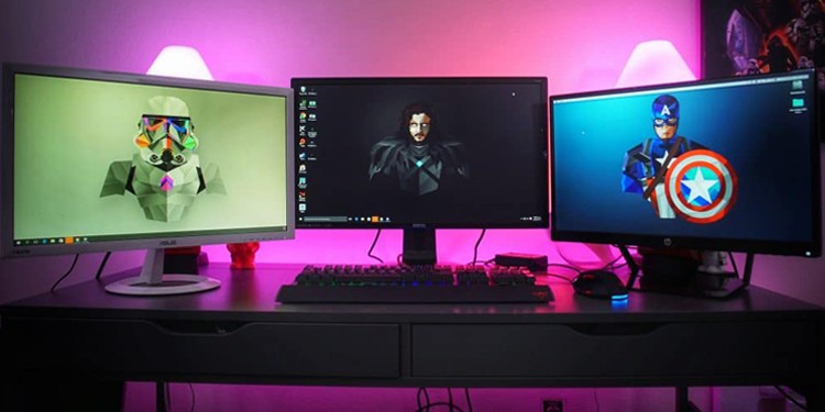
IPS displays boast 178° wide viewing angles (vs. TN’s ~160°) and richer, more accurate colors ( 100% sRGB coverage common vs. TN’s 70-80%), ideal for.
Hinterlasse einen Kommentar
Diese Website ist durch hCaptcha geschützt und es gelten die allgemeinen Geschäftsbedingungen und Datenschutzbestimmungen von hCaptcha.