









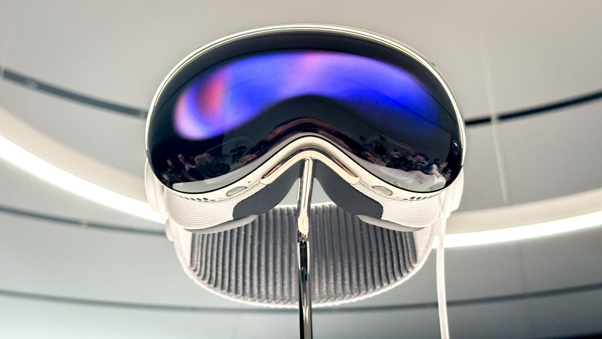
Micro OLED Module Buying Guide | Panel Type, Response Time, Brightness
Buy a micro OLED module on three numbers read under the same conditions: panel type with its real colour depth, gray-to-gray response time, and sustained brightness at your operating temperature. Peak luminance quoted without a duty cycle and response quoted without a transition tells you little about how the part behaves in a headset, a viewfinder or a handheld instrument.
Panel type comes first
Micro OLED panels divide into monochrome, colour and grayscale families, and the split changes the whole power budget. A monochrome panel emits in one colour, so there is no colour filter absorbing light and no need to drive three emitters to produce white. For a given on-screen luminance it asks for less current than a colour panel of similar area.
Colour panels build white from separate emitters or from a white emitter behind a colour filter. Both routes lose some efficiency, and the blue emitter usually ages fastest, which is why colour modules carry the more elaborate lifetime specification. If your interface only needs to show a value and a unit, monochrome is the cheaper and cooler choice.
Transparent panels form a fourth family. They pass a share of the background light while emitting their own image, which suits combiner optics and window overlays. Read transmission and luminance together rather than separately: a panel that transmits well often emits less for the same drive power, and the trade has to be settled against the ambient light behind it.
Grayscale is a separate axis from colour. A driver may accept 8-bit or 10-bit values per pixel, but the displayed steps depend on the gamma curve, the panel's own linearity and the drive scheme. High bit depth matters for waveform plots, density readings and any UI where two neighbouring levels must stay distinguishable. Test it with a gradient, not with the bit depth on the datasheet.

What response time actually measures
OLED pixels switch by moving charge, not by reorienting liquid crystal, so the physical limit is short. The published figure is a different matter. Response time is usually quoted for a specific transition, and gray-to-gray values are the ones that matter because real content rarely alternates between full black and full white.
Two panels can both claim "fast" while measuring different things: 10–90 percent rise, full on-to-off, or an average across a set of gray pairs. Ask which transition, at which temperature, with which drive condition and which measurement bandwidth. A photodiode and an oscilloscope, or a high-speed camera, will separate the claims quickly.
Temperature is the second variable. Response tends to lengthen as a panel heats, and a module specified at room temperature may behave differently inside a sealed housing next to a processor. If your application is motion-critical, request the curve rather than the single number.
Testing response yourself
Set the module to alternate between two mid-gray fields at a known interval, film the panel at a high frame rate, and step through the frames. Count how many frames the transition occupies. That count multiplied by the frame interval is your observed response, including the driver and the panel together.
Repeat at the operating temperature and at the brightness you intend to ship. Blur seen at this stage is real for your product; a better datasheet number will not remove it.
Brightness in real ambient light
The luminance on the datasheet is not the luminance you see. Ambient light reflects from the cover glass, the polariser and any air gap, and those reflections add to both the white and the black state. Contrast therefore collapses as the room gets brighter, and the loss is driven by the reflected component rather than by the panel's own black level.
Three design choices move the result: an anti-reflective coating on the outer surface, optical bonding to fill the air gap, and enough panel luminance to stay ahead of the reflected light. Bonding and coating change the reflectance; brightness buys headroom. Both are cheaper to specify than to retrofit.
Distinguish peak from sustained. A peak figure may only be available for a short burst at a defined duty cycle, with thermal rollback afterwards. For a display that runs continuously, the sustained figure at your ambient temperature is the number to design around.[1]
The power cost of brightness
OLED current scales roughly with emitted light, so doubling luminance costs close to double the power in the emitter. On a battery-powered instrument that trade is the main constraint on a sunlight-readable specification, and it is why ambient-light sensing pays for itself: the panel runs at a low level indoors and ramps up only when the environment demands it.
Content matters too. A dark UI on an emissive panel draws far less than a white background at the same nominal brightness, which is a free efficiency gain that LCD designs cannot use.
Resolution and field of view
For near-eye use, resolution has to be judged against the magnified angle rather than the panel diagonal. A small panel viewed through a lens presents a limited field of view, and pixels per degree of that field is what determines whether text is legible. Ask for the optical design's field of view and magnification along with the panel resolution, then compare candidates on pixels per degree.
Where the design has no lens, resolution should be judged against character height instead. Compute the viewing distance, pick a minimum arc height for the smallest glyph, and back out the pixel count that keeps that glyph above the limit. That calculation usually shows a modest panel is enough, and it prevents paying for pixels that the eye cannot resolve.[1]
For direct-view instruments the question is simpler: the smallest character in your UI must stay readable at the working distance, and the driver IC must support the resolution you need at the frame rate you need.
Questions for the supplier
- Which transition, temperature and drive condition does the response figure refer to?
- Is the brightness figure peak or sustained, and at what duty cycle?
- What is the lifetime definition, and at what initial luminance?
- Does the module include a driver board, or is a bare panel with a flex tail?
- What interface, supply range and connector are on the sample?
- Is there a calibration or test report per unit, or only a batch certificate?
Micro OLED modules for near-eye and instrument use are listed in our micro OLED collection, and the surrounding optics and mechanical parts sit alongside the AR and VR range. Where a design only needs a small emissive readout, a standard OLED module will usually cost less and integrate faster.
Order samples only after the three numbers are pinned to conditions you can reproduce. A module that wins on a datasheet comparison but loses on measured contrast in your enclosure is an expensive lesson, and the test takes an afternoon.
References
- ISO 9241-307:2008 — Ergonomics of human-system interaction — Part 307: Analysis and compliance test methods for electronic visual displays. International Organization for Standardization. https://www.iso.org/standard/40102.html
Weiterlesen
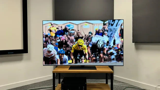
Micro OLED modules self-emit light via organic diodes, reaching ~5000 PPI for ultra-sharp visuals; crafted with LTPS backplanes and thin-film.

Select Micro OLEDs for AR/VR with sub-10μs gray-scale response (system latency <20ms to cut dizziness), 0.7" 4K panels achieving 50°+ FOV, and >1M:1.
Hinterlasse einen Kommentar
Diese Website ist durch hCaptcha geschützt und es gelten die allgemeinen Geschäftsbedingungen und Datenschutzbestimmungen von hCaptcha.