









PMOLED vs AMOLED | Key Distinctions, Advantages & Applications
Both use the same organic emitter. The difference is how each pixel is addressed. PMOLED drives a passive matrix of row and column strips with no transistor and no storage capacitor, so a pixel lights only while its row is scanned. AMOLED puts a thin-film transistor and a capacitor behind every pixel, so it holds light for the whole frame. That one difference sets the size limit, the power profile and the cost.
The backplane decides everything
A passive matrix is two sets of orthogonal strips: transparent anodes as columns, metal cathodes as rows, with the organic stack between them. A pixel exists where a strip crosses another. To light it, the driver selects one row and sources current into the columns for that row, then moves on.
An active matrix replaces the intersection with a circuit. The row line opens a transistor, the column line writes a voltage onto a storage capacitor, and the capacitor holds the gate of a second transistor that feeds the OLED. The charge is held by the capacitor and the pixel circuit, not by the organic layer itself.[1]
| Property | PMOLED | AMOLED |
|---|---|---|
| Components per pixel | Organic stack only | Two or more TFTs plus a capacitor |
| Emission | Pulsed, duty cycle 1/N | Continuous within the frame |
| Drive voltage | Higher, to reach peak brightness | Close to the OLED turn-on plus TFT drop |
| Practical size | Small modules | Phone to television scale |
Duty cycle and peak brightness
With N rows, each row is addressed for 1/N of the frame. To reach a given average luminance, the pixel must be driven far brighter than that average during its slice, and the shorter the slice the higher the peak. This is why a passive panel running many rows needs a boost converter and why the organic material ages faster at the same apparent brightness.
The peak also limits resolution. Push the row count up and the on-time per row falls toward the point where the driver cannot establish a stable current, so the image either dims or the voltage climbs beyond what the panel can take.
Drive current in a passive matrix also runs through long ITO and metal traces. Their resistance produces an IR drop along the row, so the end furthest from the driver is dimmer. Keeping that gradient imperceptible is the practical reason passive panels stay small.

Where the size limit comes from
Three effects push in the same direction. Trace resistance grows with panel width, scan time per row shrinks with row count, and the gap between adjacent strips cannot scale down indefinitely without shorts. Together they keep passive panels in the small-format range, and they cap the row count well below what a monitor needs.
An active matrix removes the timing pressure, because the pixel no longer depends on being refreshed continuously to stay lit. It also isolates each pixel from the data line after writing, which suppresses the crosstalk that a passive matrix shows as faint ghosting around bright objects.
The cost is process complexity. An AMOLED backplane needs a semiconductor layer with enough mobility to drive current—LTPS, oxide, or a stack of both—and that means more masks, tighter alignment and a larger capital investment. A passive panel needs only patterned ITO, an insulator and cathode separators.
Power depends on the image
There is no single winner. Power consumption follows the average picture level, because an emissive display only spends current on lit pixels.
For a mostly black interface—a watch face, a status readout, a menu with white text on black—the passive matrix is efficient. Unselected rows are off, and the small number of lit pixels does not need the overhead of a full active backplane. An active panel still pays for the driver IC and the leakage of its pixel circuits in the same condition.
For a photograph, a map or a video, the advantage reverses. A passive panel must drive every row at high peak current, and the resistive losses rise with the square of that current. An active panel holds each pixel at a modest, steady current in the region where the emitter is most efficient, so it consumes less at high picture levels and much less on a white screen.
Compare modules, not bare panels. A passive module carries a boost converter to reach its peak drive voltage, and that converter has its own quiescent draw; an active module carries a more complex driver IC with compensation and a higher standby budget. At low duty cycles the converter, not the emitter, can set the floor.
Lifetime and uniformity
OLED luminance decays with the charge passed through it, and the decay is faster at high current density. The pulsed drive of a passive matrix concentrates the same average light into short, intense bursts, which is harder on the material than a steady low current.
An active matrix has the opposite problem: transistors drift. Threshold voltage shifts with stress and temperature, so identical data voltages produce different currents across the panel over time. That is why AMOLED driver ICs include compensation, measuring or modelling each pixel and correcting the input signal.
Both technologies suffer differential ageing when static content stays on screen. In a passive matrix the pattern appears as a brightness difference between frequently and rarely used rows; in an active matrix it follows the shape of the fixed logo or status bar. Uniformity is judged on a defined grey field at a stated luminance, which is why the two effects are easy to confuse in a photograph.[2]
Choosing between them
Choose PMOLED when the display is small, monochrome or few-colour, mostly dark, and cost-sensitive: wearables, handheld instruments, medical readers, audio devices, simple status panels. The module is thin, the interface is a plain SPI or I2C bus, and the driver can sit on the glass.
Choose AMOLED when the image is photographic, the diagonal is larger than a few inches, the resolution is high, or the product needs a narrow bezel and a flexible substrate. Expect a longer design cycle and a supplier conversation about compensation and burn-in policy.
Check three things in either case: the duty cycle and peak luminance at the resolution you need, the specified lifetime at your operating brightness rather than at a fraction of it, and whether the module's burn-in mitigation is a screen saver, pixel shift, or nothing at all. Standard parts are listed under PMOLED displays and AMOLED display modules, with small monochrome graphics panels under graphic OLED displays.
The emitter is shared; the addressing is the product decision. Passive matrices win on simplicity and small dark interfaces, active matrices on scale and photographic content. Match the driving scheme to the picture the device will actually show.
References
- Hilsum, C. (2010). Flat-panel electronic displays: a triumph of physics, chemistry and engineering. Philosophical Transactions of the Royal Society A, 368(1914), 1027–1082. https://doi.org/10.1098/rsta.2009.0247
- ISO 9241-307:2008 — Ergonomics of human-system interaction — Part 307: Analysis and compliance test methods for electronic visual displays. International Organization for Standardization. https://www.iso.org/standard/40102.html
Weiterlesen

PMOLED utilizes an orthogonal matrix of anodes and cathodes, employing a progressive scanning method to instantaneously activate pixels with a 1/N duty.
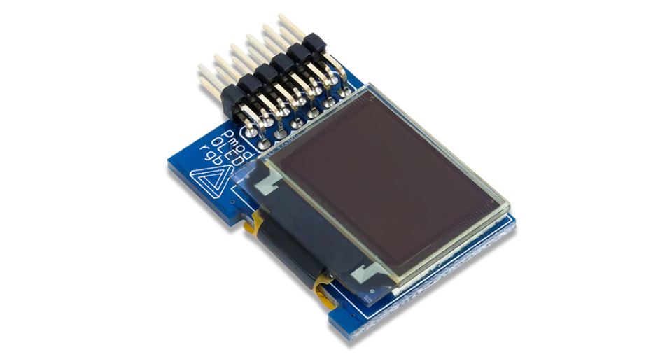
It is recommended to purchase modules under 3 inches with a resolution of 128×64. Use 4-pin I2C when I/O is limited, and select SPI for high-speed.
Hinterlasse einen Kommentar
Diese Website ist durch hCaptcha geschützt und es gelten die allgemeinen Geschäftsbedingungen und Datenschutzbestimmungen von hCaptcha.