



Where Are COG LCD Modules Used Most
COG LCD modules are used most where the display is small, the format is fixed, and the enclosure has no room for a separate driver board. That means handheld instruments and meters, thermostats and appliance panels, utility and gas meters, battery tools, simple wearables, and the status displays on industrial control panels. Medical handhelds belong to the same group.
What chip-on-glass changes
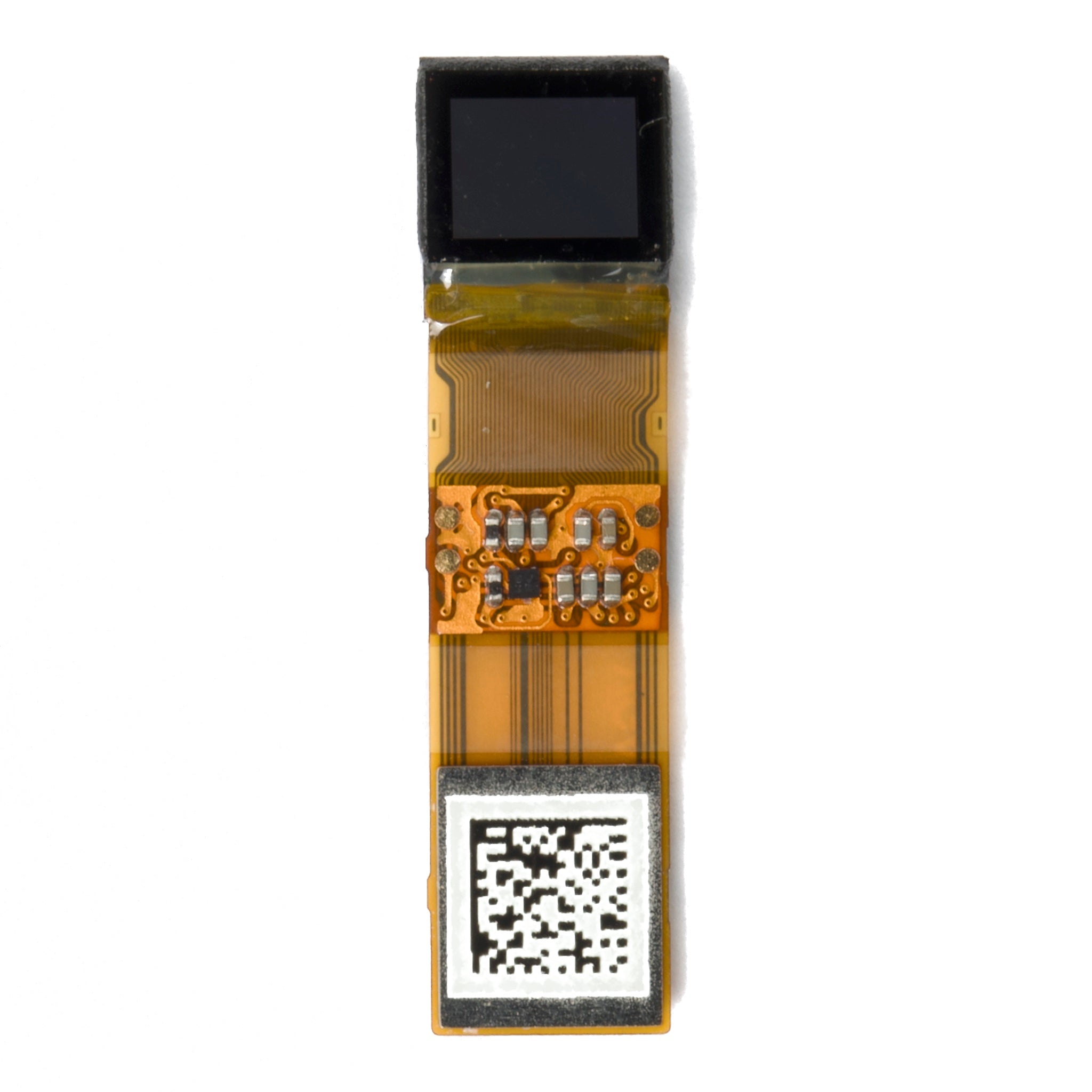
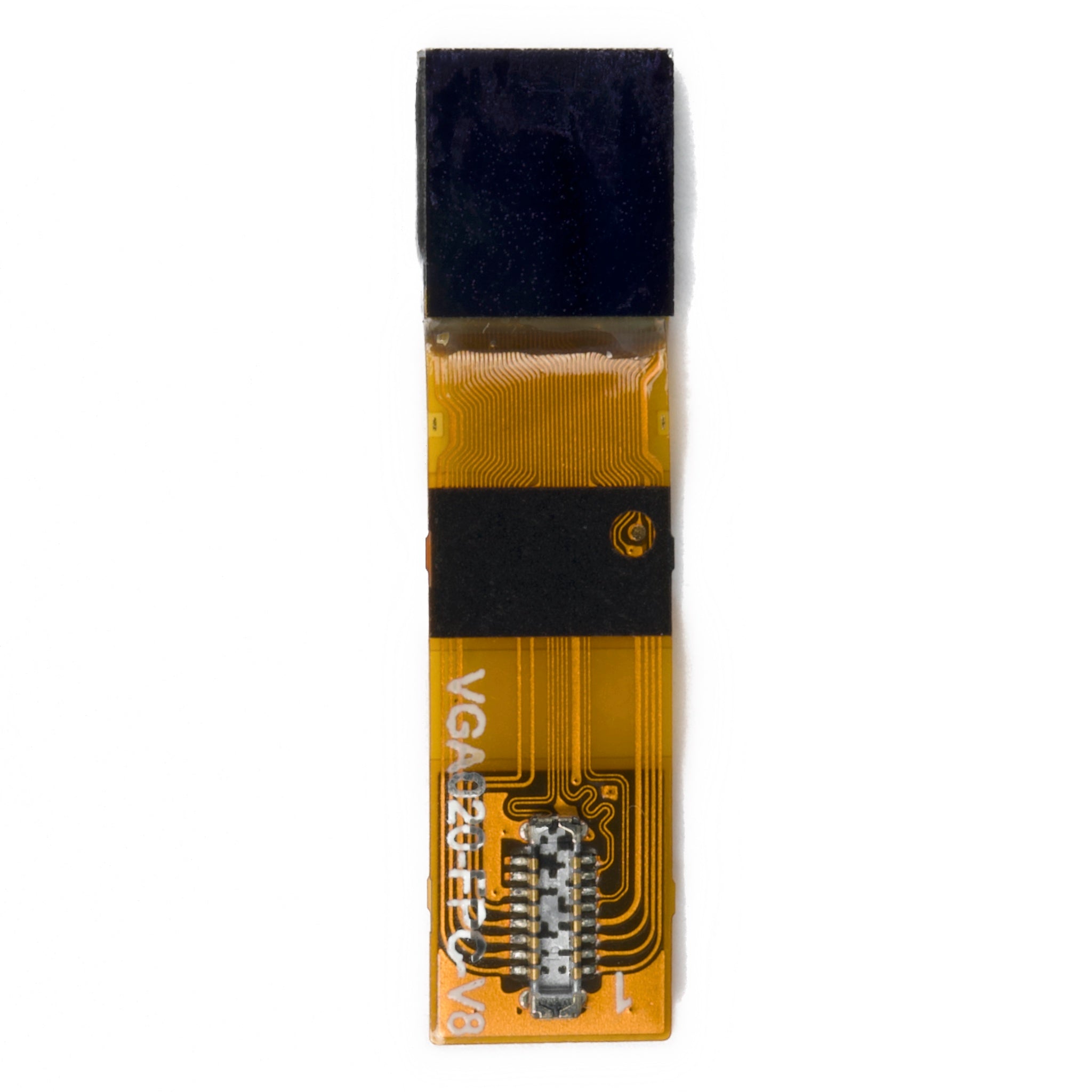
In a COG module the driver die is mounted on the display glass and connected to the ITO tracks through gold bumps and anisotropic conductive film. The controller that would otherwise sit in a package on a PCB now lives inside the outline of the panel.
A liquid crystal display needs an electro-optic effect, a transparent conductor and an addressing system, and the third of those is what COG relocates.[1] Nothing about the liquid crystal changes; only the place where the addressing electronics are mounted.
The physical consequences matter more than the electrical ones. Removing the driver package and its mating connector takes height out of the stack, so a module can be a few millimetres thick including glass and backlight. Removing the connector also removes the pin row where intermittent faults tend to start.
COG is an assembly method, not a display technology. TN, STN, FSTN and small TFT panels are all built this way, and a character module and a colour TFT can both be COG. Power draw follows the panel mode and the backlight, not the bonding method.
Why the fit is about mechanics
Three conditions point to COG: a small outline, a format that repeats across a product family, and volume high enough to justify designing glass around one die. When all three hold, COG usually beats chip-on-board on depth and beats chip-on-film on cost.
When one of them fails, the calculation changes. A single enclosure with a mid-size colour display is easier to build around a standard module, because the panel no longer has to be tooled for a specific driver. The COG LCD range covers the small formats that repeat; the rest are built to drawing.
Instruments and meters
Multimeters, clamp meters, thermometers, scales, blood pressure monitors and gas detectors share a pattern: a segment or dot-matrix display read for a second or two, battery power, and a case that gets dropped. A reflective or transflective panel is legible in daylight without a backlight, which is why the format survives in tools where a colour screen would drain the cell.
Utility meters and data loggers add a second requirement, because the display is read through a window at an angle by someone standing beside a wall box. Contrast and viewing direction therefore belong in the specification and should be measured under stated conditions rather than assumed.[2]

Appliances and building controls
Thermostats, boiler controls, wall-mounted air-conditioning units, washing machines, coffee machines and door-entry panels use COG for the same reason calculators do: a fixed set of segments and icons that does not change, made in quantities that justify custom glass.
The constraint here is temperature and humidity rather than resolution. A control behind a plastic window in an unheated plant room sees a wider range than a handheld device, so the operating grade and the polariser have to be chosen for the application instead of inherited from a catalogue part.
Wearables and compact handhelds
Fitness bands, bike computers, infusion pumps and handheld scanners want thin, light and readable in sunlight. COG helps with all three, but it is not the deciding factor; the display mode is. A transflective panel with a small backlight will outlast a transmissive panel of the same size inside the same enclosure.
Where COG does decide the design is the border. Bond pads need glass, and glass needs space, so a wearable with a very narrow bezel often moves to chip-on-film to buy back the edge.
Industrial front panels
Machine keypads, pump controllers, welding sets and vending electronics usually pair a small character or graphic display with a membrane keypad. The screen reports a setpoint or a fault code, so the format is small and the lifetime requirement is long.
In these products the display is often the part with the longest availability requirement, which makes the controller choice more important than the panel. A controller with a second source is worth more than a marginally cheaper one with a single supplier.
Where COG is the wrong answer
COG loses when the display grows, when the pixel count rises, or when the product needs a bonded cover glass or a touch stack. Larger panels spread the row and column connections over a much longer edge, and fine-pitch bonding at that scale moves to chip-on-film or to a tab process.
It also loses when the volume is low and the panel is unique. Tooling glass around one driver is a fixed cost, and a hundred units will not absorb it. For those projects a standard character LCD or graphic LCD module with a socketed driver is the cheaper route.
What to put in the drawing
Most COG problems are specification problems rather than process problems. These are the items that decide whether the second build matches the first.
| Item | Why it belongs on the drawing |
|---|---|
| Driver part number and pad pitch | Sets the bond process and the minimum glass border |
| Duty and bias | Static, half, quarter and higher multiplex change contrast and driver choice |
| Logic voltage and interface | Parallel, SPI and I2C variants are not interchangeable at the connector |
| Viewing mode and polariser | Reflective, transflective and transmissive behave differently in daylight |
| Operating and storage temperature | Drives the fluid, the polariser and the compensation method |
| Backlight type and drive current | A white LED string and an edge-lit panel need different circuits |
| Connector or FPC details | Pitch, length, contact side and stiffener decide whether it fits the housing |
| Active area and border tolerance | Cosmetic rejects usually start with an unstated tolerance |
| Temperature compensation for VOP | Contrast drift over temperature is a design item, not a defect |
Qualification and handling
Bonded glass is fragile at the pad edge. Carrying a module by its FPC, or letting the tail press against the glass in the housing, is how the first field failures appear; the module should be supported behind the bond area.
Incoming inspection should compare the drawing revision, the lot code on the label and the bond edge under magnification. A module that arrives working but with a lifted bond tends to fail after a few thermal cycles rather than on the bench.
COG is the default for small fixed-format displays in instruments, appliances, meters and compact handhelds, and the wrong choice once the panel grows or the volume falls. Decide from the border, the bond pitch and the order quantity, then state the operating mode and temperature grade explicitly.
References
- Hilsum, C. (2010). Flat-panel electronic displays: a triumph of physics, chemistry and engineering. Philosophical Transactions of the Royal Society A, 368(1914), 1027–1082. https://doi.org/10.1098/rsta.2009.0247
- ISO 9241-307:2008 — Ergonomics of human-system interaction — Part 307: Analysis and compliance test methods for electronic visual displays. International Organization for Standardization. https://www.iso.org/standard/40102.html
Weiterlesen
To effectively reduce the power consumption of an AMOLED module, the primary strategy is to minimize the illumination of pixels since black pixels are.

When buying a standard adapter, prioritize matching voltage/current (e.g., 5V/2A for basic phones, 9V/2A for fast charging) and interface compatibility.
Hinterlasse einen Kommentar
Diese Website ist durch hCaptcha geschützt und es gelten die allgemeinen Geschäftsbedingungen und Datenschutzbestimmungen von hCaptcha.