


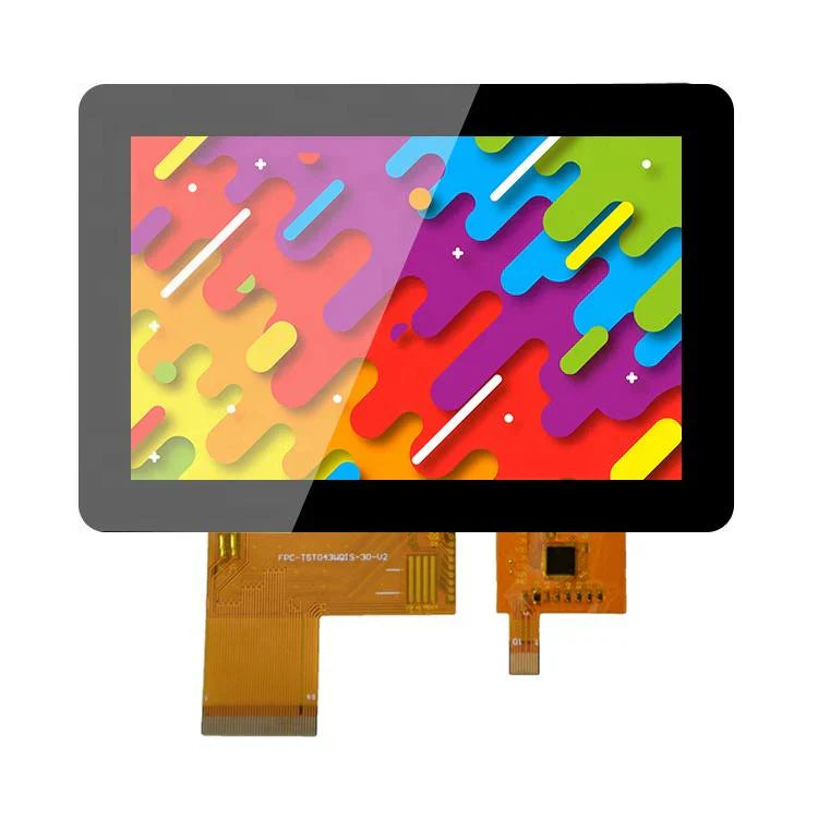
Custom LCD Display Modules | Tailored Size, Interface
Custom LCD modules are tailored to your needs. The process starts with a requirement document detailing size, resolution, interface, and operating temperature. This allows for unique shapes, integrated touchscreens, and specific driver ICs for specialized industrial or medical applications.
Size
The physical dimensions of a custom display module are the primary constraint for hardware integration.
It goes far beyond just length, width, and height data; it is the systematic starting point that directly impacts ID design, internal stacking, optical performance, and the final user experience.
Our dimensional tolerance control capability can reach ±0.15mm, supporting full-scale customization from 10.1-inch industrial HMIs to 1.3-inch wearable devices, ensuring a perfect match with your product's housing and avoiding assembly stress or light leakage due to dimensional deviations.
Physical Dimensions
How to precisely define and measure dimensions
Dimension annotation requires a clear set of specifications. We typically define dimensions according to international standards (such as VESA specifications) to ensure consistent communication.
-
Viewable Area (VA): This is the actual area that displays the image. For example, a nominal 10.1-inch module might have a VA size of 217.2mm x 135.7mm.
-
Overall Dimensions (OA): Refers to the maximum outer dimensions of the module, including the bezel (BM area) and the FPC connector. The OA determines the clearance required inside the device. Our standard OA tolerance is typically controlled within ±0.20mm, and for projects with stringent requirements, it can be improved to ±0.15mm.
-
Thickness: The module's thickness directly affects the device's slim design. The thickness of a typical embedded display module can be broken down as follows:
-
LCD Glass Thickness: 0.5mm
-
Backlight Unit Thickness: 1.8mm - 2.2mm (depending on brightness requirements and light guide plate design)
-
Total Thickness: Typically between 2.5mm and 3.5mm. Through customization, we can compress the total thickness to below 1.8mm, freeing up space for the battery or other components.
-
How dimensional tolerances affect assembly
Tolerance is not just a number; it directly relates to production line yield and long-term reliability.
A negative tolerance (module too small) may cause the screen to rattle or produce noise within the housing.
A positive tolerance (module too large) may lead to difficult assembly, or even create stress on the LCD glass when screws are tightened, resulting in "white spots" or "water ripple" effects.
We manage tolerances through precision molds and strict production process control.
For example, when customizing a display module for an industrial barcode printer for a European brand, we set the fit tolerance band between it and the metal bracket to 0.00mm / +0.10mm (module) and -0.05mm / +0.05mm (bracket), achieving an interference fit that ensured absolute stability in a vibrating environment.
Possibilities brought by non-rectangular cutting for product design
Going beyond conventional rectangles, non-rectangular cutting opens the door to product differentiation. This includes not only circles and ovals but also polygons with specific notches (such as rounded rectangles).
-
Process Implementation: Non-rectangular cutting is primarily achieved through CNC precision cutting or laser cutting. Laser cutting offers higher edge quality with a smaller heat-affected zone, suitable for more precise shapes, but at a relatively higher cost.
-
Design Considerations: When performing non-rectangular cutting, it is necessary to ensure a sufficient safety distance (typically ≥0.8mm) between the cutting line and the active circuitry of the display area to avoid damaging the traces. For instance, for a custom 1.3-inch circular AMOLED for a US outdoor sports watch brand, we ensured a distance of 1.2mm from the cutting edge to the display driver traces and adopted a special edge sealing process to enhance the module's moisture resistance.
-
Cost Impact: Non-rectangular cutting reduces the utilization rate of the mother glass and increases processing time, typically increasing the module cost by 15% to 30%.
The relationship between size and thermal design
A display module, especially a high-brightness model, is a heat source. Larger sizes or higher brightness generate more heat. The physical size design must consider the heat dissipation path.
-
Heat Density Calculation: A 15.6-inch industrial touchscreen with 1000 nits brightness might have a peak power consumption of 12W. The heat generated needs to be conducted away through structural components.
-
Cooling Solutions: When designing large-size modules, we reserve or integrate thermal pads at specific locations on the module's backplate (such as the area where the driver IC is located). These pads conduct heat to the device's metal housing or heat sink. For automotive displays operating in a wide temperature environment of -30°C to +85°C, we might even recommend customers to add heat-dissipating graphene sheets in the structural design to ensure low-temperature startup and brightness stability at high temperatures.
The table below shows the typical power consumption and thermal considerations for displays of different sizes:
| Screen Size | Typical Resolution | Typical Brightness | Peak Power (Approx.) | Recommended Thermal Considerations |
|---|---|---|---|---|
| 7.0-inch | 1024x600 | 500 nits | 3.5W | Conduction through the module's metal frame to the PCB ground plane |
| 10.1-inch | 1280x800 | 1000 nits | 6.5W | Install thermal conductive silicone pad on the housing corresponding to the driver IC |
| 21.5-inch | 1920x1080 | 800 nits | 18W | Design a metal heat sink on the back of the module and use the device's fan for active cooling |
Impact of touchscreen integration on dimensions
When a display module needs to be paired with a touchscreen (especially an add-on type), the physical dimension chain becomes longer.
The total thickness increases by the thickness of the touchscreen (e.g., 1.1mm thick cover glass).
Additionally, space for bending and fixing the touchscreen FPC needs to be considered in the design.
Resolution and PPI
Resolution refers to the total number of pixels on the screen, usually expressed as the number of horizontal pixels multiplied by the number of vertical pixels, such as 800x480 or 1920x1080 (also known as 1080p).
This number directly determines how much information the screen can display. PPI stands for Pixels Per Inch, calculated by dividing the number of pixels on the screen diagonal by the screen's diagonal size in inches.
It measures pixel density. A higher PPI value typically means a finer image, making it harder to distinguish individual pixels at a normal viewing distance.
Specific calculation methods for resolution and PPI
Understanding the PPI calculation helps in making more accurate selections. The formula is: PPI = √(Horizontal Pixels² + Vertical Pixels²) / Screen Diagonal Size (inches).
For example, comparing two 10.1-inch screens:
-
Screen A: Resolution 1280 x 800
PPI = √(1280² + 800²) / 10.1 ≈ 149 PPI
-
Screen B: Resolution 1920 x 1200
PPI = √(1920² + 1200²) / 10.1 ≈ 224 PPI
Screen B's PPI is about 50% higher than Screen A's. In practical observation, the text edges on Screen B will be smoother, and the details of fine icons will be clearer.
For users who need to read code or drawings on the screen for long periods, a higher PPI can effectively reduce eye strain.
How viewing distance affects PPI selection
The appropriate PPI needs to be combined with the typical viewing distance. The human visual system has a resolution limit at a specific distance. The farther the viewing distance from the screen, the lower the required resolvable PPI.
The table below lists recommendations for different scenarios:
| Device Type | Typical Viewing Distance | Recommended Minimum PPI | Explanation |
|---|---|---|---|
| Smartwatch/Portable Medical Device | 25 - 35 cm | > 300 | Extremely close distance, high PPI ensures sharp graphics and text without jagged edges. |
| Phone/Industrial Handheld Terminal | 30 - 40 cm | 250 - 400 | Users examine content closely, requiring high pixel density. |
| Car Center Console/Industrial HMI | 50 - 70 cm | 150 - 200 | Viewing distance is farther, a PPI above 150 ensures good clarity. |
| Outdoor Kiosk/Retail POS Machine | 70 cm - 1 m | 100 - 150 | Focus more on overall visibility and brightness, PPI in this range is sufficient. |
For example, for a center console display customized for a German automaker, with a size of 12.3 inches and a viewing distance of about 70cm.
We recommended a resolution of 1920x720, resulting in a PPI of about 182.
This value, at the given distance, achieved the goal of clear, readable text and smooth graphics rendering, while balancing the system processor's load and cost.
How resolution affects other parts of the system
Choosing a higher resolution is not just a change in the screen itself; it has a ripple effect on the entire device system.
-
Demands on Processing Performance: Rendering higher resolution images requires stronger graphics processing power. The GPU performance required to drive a 1280x800 (about 1 million pixels) screen is much lower than that required for a 2560x1600 (about 4 million pixels) screen. The processor may need to consume 30% or even more additional computational resources, which directly affects chip selection and thermal design.
-
Demands on the Transmission Interface: Increased resolution means increased data transmission volume. RGB interfaces may face EMI (Electromagnetic Interference) challenges at higher resolutions. At this point, higher-speed differential signal interfaces such as LVDS, MIPI-DSI, or eDP may be necessary. For example, an eDP interface is a more reliable choice for driving a 15.6-inch, 4K (3840x2160) resolution screen.
-
Demands on Memory: The memory occupied by the display frame buffer is proportional to the resolution. A true-color (24-bit/pixel) image at 1920x1080 requires about 6.2MB of storage space.
Practical impact of subpixel arrangement
In addition to the total number of pixels, the arrangement of subpixels (usually red, green, blue) within a pixel also affects the actual sharpness.
The most common arrangement is RGB Stripe, where each pixel consists of three side-by-side red, green, and blue subpixels.
But on some OLED screens, PenTile arrangement might be used.
This arrangement reduces the number of physical subpixels by sharing them.
For example, a PenTile OLED screen with the same nominal resolution as an RGB Stripe LCD might have an effective resolution that is somewhat lower, especially when displaying fine lines or text, where the edges may appear less sharp than on an RGB arrangement screen.
Balancing brightness and power consumption
Increasing resolution usually increases power consumption. The backlight needs to penetrate more transistors and color filters for more pixels, which can lead to a slight decrease in overall light transmittance.
To maintain the same screen brightness, it may be necessary to slightly increase the backlight brightness, thereby increasing power consumption.
When customizing a screen for an outdoor portable data terminal for a US brand, the customer had to choose between 800x600 and 1280x800 resolutions.
We provided measured data: at 500 nits brightness, the power consumption of the high-resolution version was about 8% higher than the low-resolution version.
Structural Compatibility
Specific design parameters for mounting holes
The position and type of mounting holes determine how the module is fixed. Common methods include screw holes, clips, or adhesive bonding.
-
Screw Hole Design: The mounting holes we provide are typically 0.3mm larger than the standard screw diameter (e.g., M2 screw with a Φ2.3mm mounting hole). This gap is used to absorb assembly tolerances. The torque standard for screw holes is typically set at 4-5 kgf·cm.
-
Clip Design: For consumer products that require quick assembly and reduced screw usage, clips are a common solution. The retention force of a clip is typically designed in the range of 3-5 kgf. For example, for a 7-inch display designed for a European customer's portable medical monitor, 6 clips were distributed around the perimeter, each with an insertion force of <5N and a retention force of >4kgf, ensuring the module would not loosen during a 1.2-meter drop test.
-
Adhesive Bonding Solution: When the product structure is extremely compact, leaving no space for screw posts or clips, double-sided adhesive tape is used. We typically recommend using 3M VHB (Very High Bond) series tape, with a typical thickness of 0.5mm or 1.0mm and a peel strength reaching ≥ 20 N/cm.
Wiring and bending requirements for connectors and FPC
The Flexible Printed Circuit (FPC) is the bridge connecting the display module to the mainboard, and its routing directly affects the structural design.
-
Connector Type: Commonly used connectors include 0.5mm pitch FPC connectors. The insertion force of the connector is typically 30-60N, and the extraction force needs to be ≥5N to ensure stable contact in vibrating environments. The height (Z-axis space) of the connector is a key dimension to focus on, with common heights ranging from 2.0mm to 3.5mm.
-
FPC Bend Radius: When routing the FPC in a confined space, the minimum bend radius must be ensured. Dynamic bending areas (like in clamshell phones) require a radius greater than 5mm, while static fixed bends require a radius greater than 1.5mm. Violating this rule can lead to trace breakage.
-
Electromagnetic Shielding: To pass FCC/CE and other EMC certifications, the FPC may need to be covered with an electromagnetic shielding film (like 3M 1181) or have a metal shield designed.
Matching module thickness with device internal space
The thickness of the display module is one of the core constraints for device slimness design. The total module thickness is the sum of the thicknesses of each material layer.
The table below breaks down the thickness composition using a typical 5-inch TFT-LCD module as an example:
| Component Layer | Typical Thickness Range (mm) | Achievable Thickness with Slimming (mm) | Explanation |
|---|---|---|---|
| Upper Polarizer | 0.1 - 0.15 | 0.08 | Using thinner materials, but scratch resistance may slightly decrease |
| LCD Glass (Cell) | 0.4 (0.3t glass) | 0.3 (0.2t glass) | Using thinner glass substrates, cost increases, strength slightly decreases |
| Lower Polarizer | 0.1 - 0.15 | 0.08 | Same as upper polarizer |
| Light Guide Plate (LGP) | 1.0 - 1.2 | 0.6 - 0.8 | Main thinning achieved by optimizing dot pattern design and materials |
| Reflector Sheet/Optical Films | 0.3 - 0.5 | 0.2 - 0.3 | Using thinner film materials |
| Backlight Metal Frame/Plastic Bracket | 0.8 - 1.2 | 0.5 - 0.8 | Structural optimization, weight and thickness reduction while ensuring strength |
| Total (Approx.) | 2.7 - 3.5 | 1.8 - 2.3 |
Through customization, the total thickness can be reduced from the standard 3.2mm to 2.0mm, freeing up nearly 1.2mm of thickness space for the battery, thereby increasing battery capacity by about 15%.
Thermal design and long-term reliability
Display modules, especially high-brightness models, generate heat during operation. If the heat is not dissipated in time, it can accelerate the aging of liquid crystal materials and cause brightness decay.
-
Main Heat Source: The driver IC is the main heat source, and its operating temperature needs to be controlled within the range of -40°C to +85°C. At an ambient temperature of 25°C, the surface temperature of the driver IC may reach 50-60°C.
-
Heat Dissipation Path Design: An effective heat dissipation path involves conducting heat from the driver IC to the module's metal bracket or backplate, and then through a thermal conductive silicone pad (typically 0.5mm or 1.0mm thick, with a thermal conductivity of 1.5-3.0 W/m·K) to the product's metal housing. For example, for a custom 10.1-inch high-brightness (1500 nits) module for an outdoor bar-type display, we reserved a Thermal Interface Material (TIM) filling area at the position corresponding to the driver IC to ensure the IC junction temperature does not exceed 80% of its maximum junction temperature (Tj max).
-
Coefficient of Thermal Expansion (CTE) Matching: The CTE of the materials used in the module (such as glass, metal frame, plastic bracket) and the product housing material (such as aluminum-magnesium alloy, PC/ABS) need to be matched. In wide temperature cycle tests from -30°C to +70°C, excessive CTE differences can cause structural stress, leading to noise or even cracking.
Optical Performance
How bright is the screen:
Brightness is measured in candelas per square meter (cd/m²), commonly known as nits. This parameter determines the screen's readability in bright environments.
-
Indoor Applications: Such as office equipment, home appliance panels, brightness is typically between 250 and 400 nits.
-
Outdoor or High Ambient Light Applications: Such as outdoor payment terminals, industrial outdoor handheld devices, car center consoles, require higher brightness to combat direct sunlight. The brightness of such screens is typically in the range of 800 to 1500 nits, or even higher. For example, to meet the needs of a US construction machinery manufacturer, we customized the brightness of their vehicle display to 1200 nits, ensuring operators could clearly read data even in midday sunlight.
-
Brightness Uniformity: This refers to the consistency of brightness across different areas of the screen. We measure it with "Luminance Uniformity," calculated as (Minimum Brightness / Maximum Brightness). The industry typically acceptable standard is ≥80%. For high-end medical diagnostic displays, this requirement increases to ≥90%.
Contrast Ratio:
Contrast ratio is defined as the ratio of the screen's maximum brightness (when displaying white) to its minimum brightness (when displaying black). High contrast makes the image appear more layered, with purer blacks.
-
Measurement Method: Contrast ratio is divided into static and dynamic. We usually use the static contrast ratio (measured within the same frame) as the standard parameter. The static contrast ratio of conventional TFT-LCDs typically ranges from 800:1 to 1500:1.
-
Influencing Factors: Contrast ratio is mainly affected by the ability of the liquid crystal molecules to control light (OD value) and backlight leakage. By improving the performance of the liquid crystal material and optimizing the panel's circuit design, the contrast ratio can be increased to 2000:1.
-
Relationship with Brightness: Increasing screen brightness can sometimes exacerbate backlight leakage when displaying black, leading to a decrease in contrast ratio.
Color Gamut:
Color gamut represents the range of colors a screen can reproduce. It is usually expressed as a percentage of a standard color space (such as sRGB or NTSC).
-
Common Standards: sRGB is the standard color space for web content and most software. 100% sRGB coverage means the screen can accurately display all colors defined by the standard. NTSC is another, older television standard; 100% sRGB is approximately equal to 72% NTSC.
-
Typical Values: The color gamut coverage of an ordinary display module is about 70% NTSC (approximately equal to 97% sRGB). By using high-performance color filters and LED backlights, the color gamut can be increased to 85% NTSC or even above 100% sRGB. Wide color gamut screens (e.g., covering 90% DCI-P3) can display more vibrant reds and greens, mainly used in high-end photography, video editing, and other professional fields.
-
Color Accuracy: An important parameter related to color gamut is color accuracy, measured by Delta E (ΔE). It measures the deviation between the displayed color and the standard color. A lower ΔE value indicates more accurate color. When ΔE < 3, the human eye can hardly perceive the color difference. For graphic design monitors, we require an average ΔE value of < 2.
What happens when viewing the screen from different angles
Viewing angle defines the angular range from which the eye can view the screen without significant color and contrast distortion.
-
Measurement Standard: The viewing angle is typically defined as the angle at which the contrast ratio drops to 10:1. For example, a "viewing angle of 178°/178°" means that even from a position almost parallel to the screen, the image content can still be recognized, although color and brightness will be attenuated.
-
Technology Impact: Early TN (Twisted Nematic) technology had narrow viewing angles, with significant color shift and contrast degradation when viewed from the side. Mainstream IPS (In-Plane Switching) technology has improved the viewing angle to 178°/178°, maintaining color consistency from most viewing directions.
How optical performance parameters interact
These optical parameters are not isolated; they are interrelated and sometimes require trade-offs.
-
Brightness and Color Gamut: Using a wider color gamut LED backlight (such as KSF phosphor) can increase the color gamut, but its luminous efficiency might be slightly lower than standard white LEDs, potentially resulting in slightly lower brightness at the same power consumption.
-
Brightness and Uniformity: When pursuing ultra-high brightness, increasing the current of the LED light bar may cause the center area of the screen to be brighter than the edges, making brightness uniformity more difficult to control.
Interface
Selecting the interface for an LCD display module is a crucial step in connecting the display unit to the main control system.
The interface type determines the data transmission method, speed, and system complexity.
For example, for an 800 x 480 pixel touchscreen used in an industrial controller, using an RGB interface might require more than 24 pins; switching to a MIPI DSI interface, only 5 cables are needed to achieve higher-speed data transmission and reduce power consumption to below 30 milliwatts.
Common Interface Types
Selecting the interface for an LCD display module is akin to choosing a transmission channel for digital signals.
Different channels have significant differences in width, speed, and noise immunity.
The following provides a detailed analysis of the working principles and performance parameters of several major interfaces.
Microcontroller Interface (MCU Interface):
This interface maps the display module as a memory-mapped device of the microcontroller. The processor writes instructions and image data directly through a parallel data bus, achieving low-level control of the display.
Data transmission is based on an 8-bit or 16-bit wide data bus, accompanied by read/write control lines (e.g., WR, RD), chip select line (CS), and register select line (RS).
When writing pixel data, a typical operation sequence is: the processor first specifies the target as the frame memory via the RS line, then places the 16-bit pixel color value (e.g., in RGB 5-6-5 format) on the data bus, and finally triggers the falling edge of the WR line to latch the data into the memory inside the module.
Taking a system integrating an STM32H7 series processor as an example, when driving an 800x480 resolution screen using a 16-bit parallel interface, theoretically writing the entire frame buffer alone requires about 768,000 bus operations.
The advantage of this interface is its strong real-time control capability, but it continuously occupies processor resources.
Some modern microcontrollers integrate an LCD-TFT controller, which can automatically read data from the internal frame memory and generate corresponding timing signals, thereby freeing up the processor.
RGB Interface:
This interface separates the process of graphics generation from display refresh.
The main processor is responsible for writing the complete frame image data to a dedicated frame buffer memory, while the display module continuously reads data from this memory and refreshes the screen.
Interface signal lines include pixel clock, vertical sync, horizontal sync, and data lines. The width of the data lines is commonly 16-bit (RGB565), 18-bit (RGB666), and 24-bit (RGB888).
For a 1024x768 resolution display using a 24-bit RGB interface at a 60Hz refresh rate, the pixel clock frequency needs to reach 1024 * 768 * 60 ≈ 45MHz.
The data throughput is approximately 45 million pixels/second * 3 bytes/pixel = 135MB/s.
Serial Peripheral Interface (SPI):
When the number of available pins on a microcontroller is limited, the Serial Peripheral Interface provides an effective solution.
It communicates via a single, high-speed serial data line, accompanied by a clock line and a chip select line.
Data transmission is organized in the form of data packets. For example, during initialization, the host first sends a command code to configure the display module, followed by command parameters.
When transmitting image data, it first sends the command code to write to the frame memory, then continuously sends a stream of pixel data.
For a color display with a resolution of 320x240, each frame contains 153,600 pixels.
Assuming each pixel is represented by 16-bit color depth, the data volume for one frame is 307,200 bytes.
Under an SPI clock frequency of 30MHz, ideally transmitting one frame of data takes about 82 milliseconds, equivalent to a refresh rate of about 12 frames per second.
Therefore, this method is more suitable for interfaces where graphics change infrequently, or for small-sized displays.
Low-Voltage Differential Signaling Interface (LVDS):
As resolution increases to Full HD (1920x1080) or higher, the number of signals, synchronization timing, and electromagnetic interference issues of parallel interfaces become difficult to manage.
Low-Voltage Differential Signaling technology solves this problem through differential signal transmission.
Each LVDS data channel uses a pair of differential lines (D+ and D-) to transmit signals.
This differential structure inherently suppresses common-mode noise and allows the use of lower signal voltage swings (typically around 350mV), thereby reducing electromagnetic radiation and power consumption.
A typical LVDS display channel configuration contains 3 or 4 data channel pairs and 1 clock channel pair.
Each data channel can transmit 7 bits of data in a single clock cycle.
For a 1080p@60Hz display, the total data rate is approximately 1920 * 1080 * 24 * 60 ≈ 3.0 Gbps.
Using an LVDS interface with 4 data channels, each channel needs to handle a rate of about 750Mbps.
MIPI DSI (Display Serial Interface):
This is the mainstream high-speed serial interface in the mobile consumer electronics field, with its design deeply optimized for power consumption, speed, and electromagnetic compatibility.
Unlike the continuous signal stream of LVDS, this interface uses a packet-based communication protocol.
Data transmission is organized into packets with error checking, making the transmission smarter, more efficient, and supporting mixed transmission of various commands and data.
The physical layer of the interface consists of 1 clock lane and 1 or more data lanes. The transmission rate of each data lane can range from hundreds of Mbps to several Gbps.
The interface supports multiple power-saving states. For example, when displaying a static image, the bus can enter an ultra-low power standby state, waking up only when the screen content needs updating, which greatly reduces average power consumption.
Due to the complexity of its protocol, it usually requires native support from the main processor and strict PCB layout rules to control signal integrity.
How to Choose
First, confirm what you need to display and the required speed
The data transmission capability of the interface must meet the needs of content updates. Display content can be roughly divided into three levels:
-
Static Text and Simple Graphics: For example, status screens on industrial equipment, sensor reading dials. Such interfaces update slowly, with frames per second potentially below 10 fps. The total data volume is small.
-
Dynamic User Interface: For example, touchscreens for home appliances, portable device menus. Involves page switching, icon animations, requiring smoothness of 30fps or higher.
-
Full-Motion Video: For example, in-car navigation, streaming media playback devices. Requires full frame rate playback at 60fps or higher, with the highest data throughput.
The theoretical data rate can be calculated from resolution, color depth, and refresh rate. The formula is:
Data Rate (bps) = Horizontal Pixels × Vertical Pixels × Bits per Pixel (Color Depth) × Refresh Rate (Hz)
For example, for an 800x480 resolution, 24-bit color depth, 60Hz refresh rate display, the required bandwidth is:
800 × 480 × 24 × 60 ≈ 553 Mbps.
This value is the baseline for interface selection. An SPI interface at conventional speeds (e.g., 50MHz) can hardly meet this demand, while RGB, LVDS, or MIPI DSI are reasonable choices.
Check what resources are available on your main control chip
The interface support of the main control chip is a hardware limitation that cannot be bypassed.
-
Number of Pins: Microcontrollers with a low pin count may only provide 1-2 serial interfaces. For example, an STM32G0 series chip with only 48 pins, after connecting power, clock, memory, and other necessary peripherals, the remaining general-purpose I/O pins might only be enough to connect an SPI interface screen, but not enough to drive a parallel MCU interface screen requiring more than 20 pins.
-
Native Support: Modern application processors typically natively integrate high-performance display controllers. For example, NXP's i.MX RT series processors might support parallel RGB interface and MIPI DSI interface simultaneously.
-
Processing Power: When using an MCU interface, the processor needs to continuously participate in data writing, occupying CPU time. When using an RGB interface, if the chip includes a graphics accelerator or DMA controller, it can significantly reduce the CPU's burden.
Evaluate PCB layout and signal integrity requirements
The interface type directly affects the complexity and reliability of the printed circuit board.
-
Routing Space: Parallel interfaces require routing a large number of traces. A 16-bit parallel MCU interface, plus control lines, might require over 20 signal lines. On a compact circuit board, finding routing paths for these lines can be very difficult. MIPI DSI or SPI interfaces require only 3-5 pairs of differential lines or single-ended lines, greatly saving routing space.
-
Signal Integrity: Single-ended parallel signals are prone to electromagnetic interference and ringing at high speeds. In long-distance transmission or noisy environments (e.g., near industrial motors), differential signal interfaces like LVDS or MIPI DSI, with their common-mode noise rejection capability, ensure more stable image quality.
-
Electromagnetic Compatibility (EMC): High-speed single-ended signals (like parallel RGB) are a major source of electromagnetic radiation. For products that need to pass strict EMC certifications like FCC and CE, using low-voltage swing differential signal interfaces can significantly reduce testing and shielding difficulties.
Calculate the total cost of the interface solution
Cost assessment needs to cover chips, components, assembly, and other aspects.
| Cost Component | Parallel MCU Interface | RGB Interface | SPI Interface | LVDS Interface | MIPI DSI Interface |
|---|---|---|---|---|---|
| Main Control Chip Cost | Medium | High (requires powerful GPU or external controller) | Low | High | High |
| Display Module Cost | Low | Medium | Low | High | High |
| Potential Additional Cost | None | May require external SDRAM as frame buffer | None | May require a serializer | May require a serializer |
| PCB Manufacturing Cost | High (more layers, complex routing) | High | Low | Medium (impedance control requirements) | High (strict impedance control) |
For example, choosing a MIPI DSI interface for a simple status display screen, while offering surplus performance, would lead to a significant increase in the cost of the main control chip and display module, and higher PCB process requirements.
Consider power consumption and thermal management
For battery-powered portable devices, the power consumption of the interface directly affects battery life.
-
Static Power Consumption: High-speed interfaces like LVDS and MIPI DSI can enter very low-power sleep states during transmission intervals. For example, MIPI DSI can turn off data lanes when displaying static images, keeping only the clock active, reducing power consumption to the microwatt level.
-
Dynamic Power Consumption: The capacitive load and voltage swing on the interface bus determine dynamic power consumption. Parallel interfaces, due to the need to switch many single-ended signals simultaneously, have relatively high power consumption. Differential signal interfaces have low voltage swings and lower dynamic power consumption.
-
Integration Level: Highly integrated interfaces (like MIPI DSI) reduce the use of external logic chips, which also helps lower overall system power consumption and heat generation.
En lire plus
To choose an LCD module, first define requirements: size (e.g., 2.4"), resolution (e.g., 320x240), and interface (SPI for simplicity, MIPI for speed). Check operating temperature (-20°C to 70°C for...
Choose OLED for superior contrast (over 1,000,000:1), faster response (microseconds vs milliseconds), and wider viewing angles. It's ideal for high-end devices. Select LCD for higher maximum bright...
Laisser un commentaire
Ce site est protégé par hCaptcha, et la Politique de confidentialité et les Conditions de service de hCaptcha s’appliquent.