









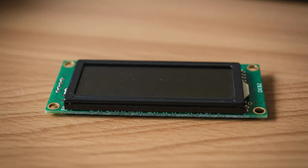
How to Design a Custom LCD Display Module for Your Product | From Specification to Mass Production
A custom LCD module project moves through specification, glass and driver selection, flex and mechanical design, sample validation, tooling and quality control. Two stages decide whether the rest runs smoothly: the interface definition and the acceptance standard. Both should be frozen in writing before tooling is ordered, because everything after that point is expensive to change.
Start from the window
Begin with the mechanical window, the reading distance and the content, not with a catalogue size. A small window that must show eight lines of text forces a choice between a larger module, fewer lines and a smaller font, and only the reading distance settles which of those is acceptable.
Build a 1:1 mock-up of the window with printed content before the drawing is approved. It exposes what a dimension drawing hides: bezel width, finger clearance, the angle the operator actually stands at, and whether the window sits where the eye expects it.

Pixel density and bus load
Resolution drives two costs that are easy to miss: frame buffer size and bus bandwidth. A 320×240 frame at 16 bits per pixel needs about 150 KB, while 800×480 at 24 bits needs roughly 1.15 MB before double buffering. If the host cannot hold that, the interface has to change or the resolution does.
SPI keeps the pin count low and suits small panels, but its throughput limits refresh as resolution rises. An MCU parallel bus raises throughput at the cost of I/O pins. RGB parallel and LVDS suit medium and large panels, and MIPI DSI suits high pixel density but needs lane count, timing and initialisation support on the host side.
Compare buses with all three conditions stated: resolution, colour depth and clock rate. Any one of them alone says nothing useful about the frame rate a product will achieve.
Brightness for the environment
Required luminance follows the light falling on the screen, not the product category. An indoor panel, a semi-outdoor terminal and sunlit equipment sit in different ranges, and the cover glass can shift effective contrast more than the backlight does.
Specify brightness at the assembled stack. A strong backlight behind a reflective unbonded cover can read worse than a moderate backlight with optical bonding and an anti-reflection coating, because reflected ambient light lifts the black level and compresses the contrast the user sees.
Decide the thickness budget in the same conversation. Glass, polariser, light guide, touch sensor, adhesive and cover add up, and thinning any layer usually costs brightness, uniformity or impact resistance.
Viewing direction and polariser
Polariser orientation is fixed at assembly and cannot be corrected in firmware. A landscape product expects the twelve o'clock direction and a portrait product the six o'clock direction; reversing them produces grey inversion when the operator looks from the side.
Put the viewing direction on the purchase drawing and confirm it with an off-axis photograph at sample approval. Wide viewing is not free either: an in-plane switching arrangement reduces the angular sensitivity of the liquid crystal layer, and compensation films in the polariser stack do much of the remaining work, but neither removes the change in contrast with angle entirely.[2]
Glass and driver IC
Glass selection fixes the operating temperature range, the twist mode and the threshold voltage, and it is the parameter most often checked last. Confirm the range against the real internal temperature of the enclosure, not the bench temperature, because a sealed housing in sunlight runs well above ambient.
The driver IC must match resolution, interface, colour depth and frame rate at the same time, and its Gram size limits the addressable resolution. Ask for the datasheet and an initialisation sequence for the exact revision before layout. A part-number match is not enough: revisions of the same device can change register maps and default settings.
Bonding method belongs in the same decision. Chip-on-glass removes the external board and shortens the interconnect, which helps both EMI and thickness, while a chip-on-board arrangement is easier to rework. The COG LCD format is the usual choice for character and small graphic modules.
Flex and mechanical stack
The flex carries signal integrity and assembly yield at once. Trace width and spacing, gold-finger pitch, stiffener thickness and layer count all interact with the connector and the bend path. A finer pitch saves space and wears faster under repeated mating, so match the pitch to the number of insertion cycles the product expects.
Route high-speed pairs with controlled impedance and keep them clear of switching supplies. Where a flex must run parallel to a power line, add a ground or shield layer rather than relying on spacing alone.
Design the test jig alongside the flex. A pogo-pin jig that powers the module without the main board turns a wiring argument into a five-minute check, and it is far cheaper than a revision of the flex.
Sample validation
Validate in the real enclosure with production firmware, the production connector and the final flex path. Measure optical performance on the assembled stack with a calibrated meter under stated conditions, and record the instrument, aperture and ambient light with every result.[1]
- Mechanical: active area against the window, flex direction, connector clearance, stack height.
- Electrical: power sequence, reset timing, sleep and wake behaviour, current at minimum supply voltage.
- Optical: luminance, contrast, uniformity and colour at the working distance and angle.
- Reliability: the temperature, humidity and vibration sequence the product specification actually requires.
Write down what counts as a failure before the tests start. A sample report that lists readings without pass limits tends to be negotiated after the fact, which is the most expensive way to settle it.
Tooling and pilot run
Tooling follows design freeze: light-guide mould, flex die-cut, cover-glass fixtures and assembly jigs. Each has its own lead time, and the jigs matter more than their cost suggests, because manual alignment of a flex is where yield quietly disappears.
Run a pilot batch large enough to expose tool wear and jig repeatability, then hold the first-article inspection against the drawing before releasing volume. Record the process window for each station, including bonding temperature, pressure and dwell, so a shift change does not change the product.
Quality control
Incoming inspection should verify revision and date code, not only part number and quantity, because mixed revisions of the same IC can behave differently once assembled. Define tolerances and visual defect limits per material category instead of applying one general rule to glass, flex, LEDs and polariser.
In-process checks belong at bonding, lamination, assembly and lighting inspection. Lighting inspection needs a fixed pattern set, a defined viewing distance and a minimum inspection time; a rushed check passes intermittent line defects that surface at the customer instead of at the line.
Pixel defects should be judged against an agreed class rather than a verbal promise of a perfect screen. ISO 9241-307 sets out defect classes and the conditions under which they are counted, which is the practical way to write the clause into a purchase specification.[1]
Take the same care with the display choice itself. Where the product needs a wide viewing angle and a bonded cover, start from an IPS display range and confirm the stack, rather than assuming a standard TFT panel will read well once the cover is fitted.
Freeze the window, the interface and the acceptance standard first, then let glass, flex, backlight and tooling follow. Projects that fail in production usually fail on a definition nobody wrote down.
References
- ISO 9241-307:2008 — Ergonomics of human-system interaction — Part 307: Analysis and compliance test methods for electronic visual displays. International Organization for Standardization. https://www.iso.org/standard/40102.html
- Hilsum, C. (2010). Flat-panel electronic displays: a triumph of physics, chemistry and engineering. Philosophical Transactions of the Royal Society A, 368(1914), 1027–1082. https://doi.org/10.1098/rsta.2009.0247
En lire plus
Round AMOLED displays are becoming a common choice for smart wearables and compact embedded devices. They are thin, high-contrast, fast in response, and.
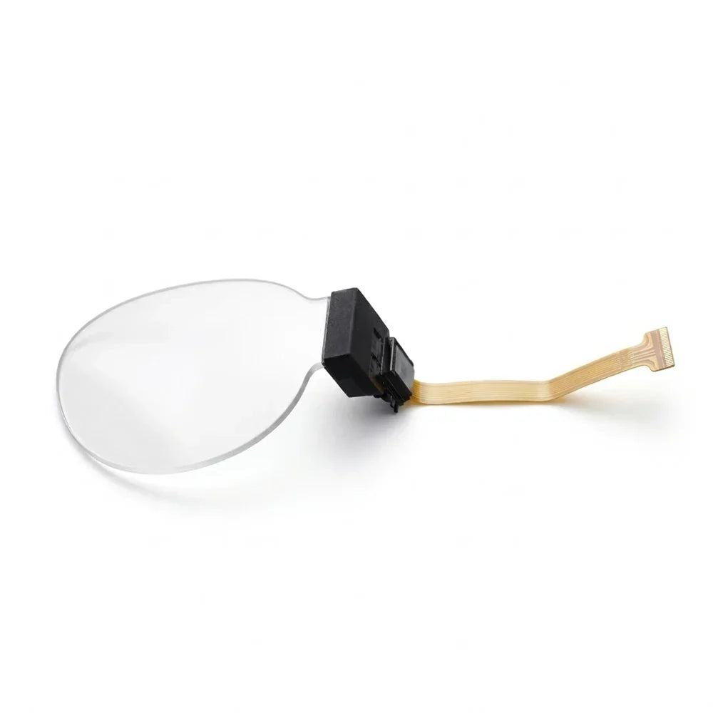
Across 12 AR-glasses prototype builds we bench-tested 28 Micro OLED microdisplays, and only 14 of them made it cleanly into a waveguide or BirdBath.
Laisser un commentaire
Ce site est protégé par hCaptcha, et la Politique de confidentialité et les Conditions de service de hCaptcha s’appliquent.