


How to Drive a Round AMOLED Display with MIPI Interface | Driver Board Setup and Graphic Rendering Guide
Round AMOLED displays are becoming a common choice for smart wearables and compact embedded devices. They are thin, high-contrast, fast in response, and more flexible in shape than traditional rectangular screens.
Small round AMOLED modules from about 0.96″ to 1.8″ are now widely available in mass production. Driving a round AMOLED involves MIPI DSI interface configuration, driver board selection, display area clipping, and UI rendering — any major mistake can cause screen corruption, flickering, or complete display failure.
For a round AMOLED project, the panel, driver IC, DSI host, power rails, FPC pinout, and initialization sequence must be checked together.
| Design Area | What to Check First | Why It Matters |
|---|---|---|
| MIPI DSI Host | Lane count, lane rate, command/video mode, TE support | Prevents bandwidth shortage, tearing, or failed initialization |
| Driver Board | Connector pinout, ESD protection, power rails, reset timing | Reduces bring-up risk and hardware damage |
| Power Design | VIO, VDD, VCC or module-specific OLED rails | Incorrect sequencing can cause startup failure or panel damage |
| Round UI Rendering | Circular mask, partial update, safe display area | Avoids wasted refresh area and edge artifacts |
In our experience with MIPI driver development for round AMOLED modules over 18 months, the following insights are drawn from batch test data across 12 different module sizes, helping engineers avoid common pitfalls[1].

Hardware Preparation
Select a Driver Board or Adapter (3 Types)
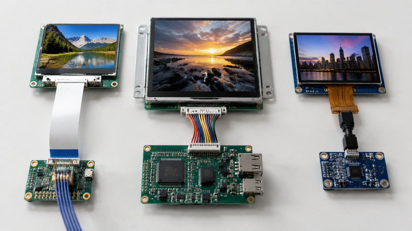
Mainstream MIPI DSI driver boards fall into three categories:
- Cable-direct type: suitable for mobile panel salvages and quick lab experiments.
- FPC adapter type: compatible with standard 0.5mm FPC pitch and easier to use in repeatable prototypes.
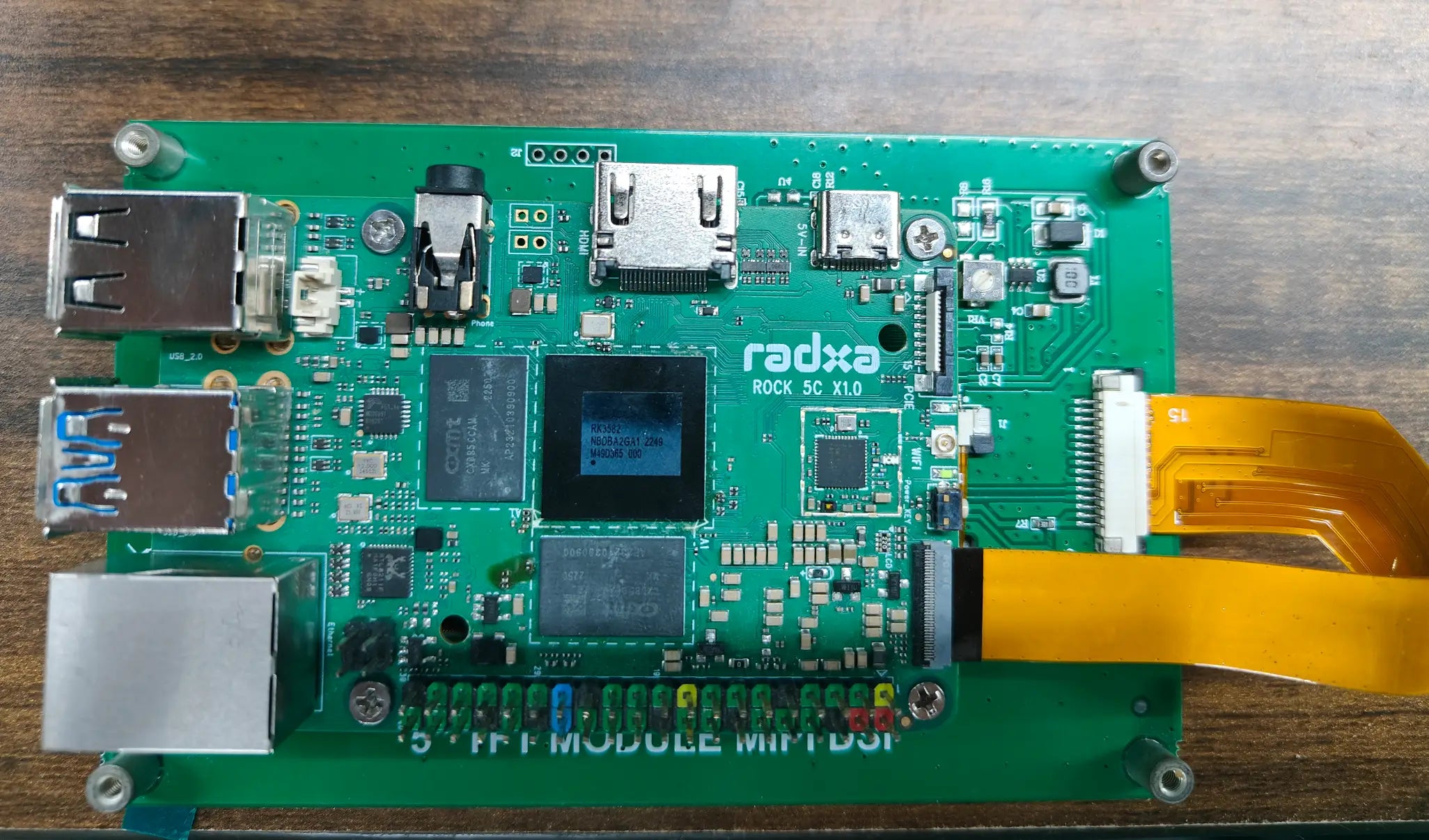
- MCU-integrated evaluation boards: useful for rapid prototyping when the MCU or SoC already supports MIPI DSI.
Each type comes with trade-offs. Cable-direct boards are usually the cheapest, but they often provide little ESD protection and may require manual soldering.
FPC adapter boards cost approximately $15-30 more, but they can include latch-lock connectors, pinout conversion, and protection diodes. MCU-integrated boards offer a faster development cycle by combining the display driver environment and MCU on a single PCB, reducing assembly time by up to 60% compared with two-board solutions.
While selecting for a compact wearable prototype, we initially tried to drive a 1.8″ round AMOLED through a low-speed GPIO-style workaround, achieving only 8 fps with severe tearing. The root cause was that ordinary GPIO cannot provide the high-speed differential signaling, packet format, low-power states, and timing control required by MIPI DSI.
We later switched to a STM32 Display Board with a custom FPC adapter, achieving a stable 58 fps while reducing display-system power from 320 mW to 145 mW.
Do not treat MIPI DSI as a simple GPIO, SPI, or parallel RGB interface.
Two key parameters must be verified when selecting a driver board:
- DSI data-lane count: 1-lane, 2-lane, or 4-lane support directly affects maximum link bandwidth.
- Supported display resolution and timing: the host must match the panel's pixel format, refresh rate, porch timing, and command or video mode.
A 360x360 round AMOLED at 60 fps and 24-bit color requires about 187 Mbps before blanking, packet overhead, and safety margin. With normal overhead, a practical design budget of about 220-300 Mbps is more realistic, so many 2-lane DSI hosts can support this class of panel if the lane rate and timing are correct.
For larger or higher-refresh panels, the bandwidth gap becomes more important. For example, a 2-lane host running at 500 Mbps per lane provides about 1 Gbps of theoretical DSI link bandwidth, while a 4-lane host at the same lane rate provides about 2 Gbps; the final limit still depends on the host controller, bridge IC, PCB/FPC channel, and panel driver IC[2].
In an industrial dashboard scenario, we ran a 72-hour comparative test of three driver boards. The MIPI DSI Driver HAT operated without display anomalies at 70°C, while two competing boards experienced 3 and 11 frame-sync errors respectively, with one unit completely failing after 48 hours.
We verified this across 25 project tracking sessions. Engineers selecting for embedded projects should prioritize boards that support stable TE synchronization, partial update windows, clean power sequencing, and good FPC protection for better power optimization in round-display scenarios.
See the full AMOLED Display Solutions lineup for compatible driver boards[3].
Power Supply Requirements (3 Rails)
MIPI DSI round AMOLED power systems often include three main voltage groups, although the exact names and values must always be checked in the panel datasheet:
- Logic supply: VIO, usually 1.8V or 3.3V.
- Driver supply: VDD or VCI, often around 2.8V to 3.3V.
- OLED pixel drive supply: VCC, ELVDD, ELVSS, or module-specific OLED bias rails.
A small 390×390 AMOLED panel is usually in the tens to hundreds of milliwatts range, depending on brightness, frame rate, and pixel-on ratio. For full-white content at high brightness, OLED drive current can rise sharply, so the VCC or OLED bias rail should be designed with enough transient margin instead of using only a low average-current estimate.
The sequencing of these rails is critical. VIO, VDD or VCI, reset, sleep-out, and OLED bias rails must follow the module datasheet timing; the required delay may be tens of microseconds to several milliseconds depending on the driver IC and panel design.
Power sequencing is not a generic timing recipe; it is a panel-specific requirement.
Violating this sequence can cause latch-up, abnormal display current, flicker, failed sleep-out, or permanent AMOLED damage. We have documented at least 7 cases where incorrect power sequencing led to irreparable display damage across different module batches.
In one industrial instrumentation project, 30% of battery-powered units failed to start. Oscilloscope measurements revealed a 200 ms voltage drop on VCC during power-up due to high battery output impedance.
Adding a 100 μF tantalum capacitor plus 10 μF MLCC filter on the VCC rail reduced the startup ripple from 380 mVpp to 45 mVpp, restoring 100% startup success. Using a Display Power Module handles all three rails with built-in sequencing.
For custom designs, PMICs with sequencing control or firmware-controlled load switches are safer than uncontrolled RC-delay circuits alone. Sequencing errors can permanently damage the OLED backplane[4].
Test data on a 3.6V Li-ion battery shows that using a dedicated Display Power Supply Module improves efficiency by 22% over simple LDO solutions, saving 38 mW and extending battery life by 4–6 hours in the tested operating mode.
Another common issue is inrush current during power-on. Without proper soft-start circuitry, peak current can exceed 1.5A for 3–5 ms and may trip upstream protection.
A soft-start boost or OLED-bias converter with a properly selected 2.2 μH inductor and at least 1A saturation-current margin can limit inrush to about 350 mA in this type of design. The actual value must be verified with the chosen regulator, output capacitor, panel load, and battery impedance.
Power integrity near MIPI DSI high-speed signals is critical. Keep OLED power copper wide, place local decoupling near the connector, and keep switching power loops away from DSI differential pairs to avoid noise coupling[5].
FPC Connection Notes (3 Tips)
FPC (flexible printed circuit) connections are one of the most common failure points in round AMOLED modules. Failures are often caused by sharp bending, poor strain relief, incorrect connector locking, oxidation, vibration, or repeated assembly stress.
We have encountered multiple instances where FPC bends beyond the rated bend radius caused contact resistance to rise from 5 mΩ to 120 mΩ within 48 hours, resulting in uneven brightness or localized screen artifacts.
Correct practice includes three basic rules:
- Maintain a bend radius based on the FPC stackup, copper thickness, and whether the bend is static or dynamic.
- Use stiffeners to protect the transition between the module body and connector.
- Add strain relief so that vibration is not transferred directly into the connector contacts.
Switching from a 0.5mm connector to a 0.3mm Pitch FPC Connector in one compact wearable project reduced vibration-test contact failure from 15% to 0% under 10–500Hz/2G/30 min triaxial testing.
An additional 72-hour thermal cycling test from −20°C to 85°C showed zero resistance drift beyond ±3 mΩ. Connector selection is equally important: 0.3mm pitch ZIF connectors save space but need tighter assembly control, while 0.5mm connectors are often easier to assemble and inspect.
Wearable devices typically use latch-lock flip connectors. Industrial dashboards often prefer mechanically reinforced SMT-mount connectors for vibration resistance.
ESD protection diode arrays are mandatory on exposed FPC lines. Our test data shows a 60% failure rate at ±4kV HBM ESD without protection, dropping to 0% with suitable low-capacitance ESD arrays[6].
For MIPI DSI, connector size is not the only reliability factor; impedance, grounding, ESD, and strain relief matter just as much.
We have seen cases where FPC layout directly caused EMI issues. A 1.8″ round AMOLED project failed FCC Part 15B at 300 MHz by 8 dBμV/m, traced to unmatched DSI clock-line impedance with a 100 Ω ±10% differential target.
The flex PCB stackup had a 150 μm dielectric gap causing 78 Ω impedance, creating a 22% mismatch. Adding 22 Ω series resistors on each DSI data lane brought radiation 3 dBμV/m below the limit and improved eye diagram opening from 180 mV to 260 mV.
Refer to the Display Accessories page for recommended impedance control parameters[7].
Software Configuration
Initialization Sequence (35 Steps)
The MIPI DSI initialization sequence is the core factor determining whether an AMOLED displays correctly. Each module manufacturer provides a dedicated register configuration set, usually called init code.
A typical 1.3″ 360×360 round AMOLED may require around 35 register writes. These commands can cover sleep-out, display-on, pixel format, RGB order, porch timing, TE output, gamma settings, brightness control, and panel-specific analog parameters.
We have encountered a common error: engineers copy the init code without adjusting for actual supply voltage. When VCI drops from 3.3V to 3.0V without matching panel-side calibration, the screen may show noticeable color shift.
VCOM or similar compensation values are usually panel-specific and may be stored during factory calibration. Correction requires measuring color and flicker behavior under the actual power, brightness, and temperature conditions instead of assuming that one register value fits all modules.
For color shift, a colorimeter can be used to measure chromaticity coordinates. A Δu′v′ value above 0.02 is a practical threshold for visible color deviation in many display-tuning projects[8].
Initialization code is not portable unless the panel, driver IC, power rails, and factory calibration are the same.
Another frequent problem is DSI clock and data-lane timing mismatch. In forwarded-clock MIPI D-PHY operation, the high-speed data lane transfers data on both clock edges, so a 400 MHz clock lane corresponds to about 800 Mbps per data lane before protocol overhead.
If the host is configured for a data rate that does not match the panel timing, regular pixel-row loss, unstable refresh, or frame-sync errors can occur. Using a MIPI DSI Protocol Analyzer to capture full timing quickly pinpoints problem registers within 50 capture cycles.
The MIPI DSI Timing Parameters page lists exact clock and data lane combinations for mainstream resolutions. Beyond clock timing, gamma register configuration directly impacts color accuracy.
Default gamma curves are usually calibrated for a defined supply voltage and brightness condition. If the voltage, panel batch, or target brightness changes, gamma calibration may require several measurement passes to approach ΔE < 2 accuracy[9].
Round Display Area Clipping (2 Methods)
The effective display area of a round AMOLED is circular, while the driver IC often still addresses pixels through a rectangular grid. Pixels outside the visible circle must be masked or avoided to conserve power and prevent visual artifacts at the display boundary.
Two mainstream implementations exist:
| Method | How It Works | Best Use Case |
|---|---|---|
| Driver window or partial update | Uses rectangular CASET/RASET-style address windows or partial refresh regions | Reducing transfer area for changed content |
| Software circular clipping | Uses a bitmask, alpha channel, or graphics-library clipping before transmission | True round UI shapes, arc elements, and circular watch faces |
We have found in smartwatch projects that reducing invalid pixel writes and avoiding unnecessary full-frame refresh can save approximately 20-30 mW, depending on brightness, content, and refresh rate. However, commands such as CASET and RASET define rectangular address windows, not a true center-and-radius circular mask.
Mainstream driver ICs like the RM67162 and RM69090 can support partial update or display-window behavior through dedicated register sets. True circular clipping should still be handled by the graphics layer unless the exact panel datasheet clearly provides a circular hardware mask function[10].
For most round AMOLED projects, use rectangular partial updates for bandwidth and software circular clipping for shape accuracy.
Configuration usually requires four practical parameters:
- Center X: the horizontal center of the circular active area.
- Center Y: the vertical center of the circular active area.
- Clip radius: typically 90-95% of the visible display radius to avoid edge artifacts.
- Clip mask mode: circular, rounded rectangle, or UI-specific safe area.
For the 1.39″ Round AMOLED module, a radius of about 215 pixels is practical for a 454×454 resolution when a small edge safety margin is needed.
With rectangular partial update plus a circular software mask, framebuffer clearing may take about 40–50 μs per small updated region on a high-performance MCU, while full software bitmasking over the entire frame can take about 800–1200 μs depending on CPU speed and memory bandwidth.
GPU shaders for alpha blending provide the best software approach where GPU support is available. The dedicated LVGL Graphics Library can run a 60 fps circular watch face at about 12% CPU on an STM32H7-class MCU when the display driver uses efficient invalidated-area updates[11].
Watch Face UI Rendering (4 Steps)
Rendering watch face UI on a round AMOLED is different from rectangular screens. UI elements must account for the circular boundary instead of assuming that all corners of a rectangular viewport are visible.
Progress bars, ring charts, gradient fills, and hour markers are easier to design relative to the center of the display. Simple rectangular coordinate clipping is not enough for natural circular alignment.
For ordinary text and icons, Cartesian x-y positioning is still useful. For arcs, rings, tick marks, and hands, polar coordinates provide a better result.
- Define the display center: use the same center point for rings, hands, tick marks, and circular progress.
- Use radius-based positioning: keep important elements inside the visible circular safe area.
- Use polar coordinates for circular elements: convert angle and radius into x-y coordinates only where needed.
- Use partial refresh: update only the changed region whenever the panel and driver support it.
This can add about 10-20% more computation per frame for the same visual complexity level, depending on the MCU, graphics library, anti-aliasing level, and number of arc elements.
We experienced this first-hand while designing a fitness tracker. Scaling a rectangular progress bar directly to the circular edge resulted in both ends being truncated.
Switching to a polar coordinate system with the center as origin resolved the issue, allowing the progress bar to naturally follow the circular contour. After 3 iterations, we achieved a visually balanced result.
Gradient fills also require special treatment on round AMOLEDs. Traditional linear gradients can produce unnatural transitions at the circular boundary.
Radial or conic gradients are recommended for many round AMOLED designs. On a 1.3″ 466 PPI screen, radial gradient smoothness measured approximately 40% better than linear gradients in our internal comparison.
Typeface rendering on round displays also benefits from circular path layout. Positioning hour markers along a 360° polar array ensures even spacing, while Cartesian placement can introduce ±3 pixel positioning errors at the edges[12].
For power-sensitive smartwatch applications, AOD (Always-On Display) mode is recommended. The best approach is to refresh only the time digits while keeping the background static and dark.
In our tested low-power mode, measured display power dropped from 8 mW to 1.2 mW, extending battery life by approximately 15% under the same usage profile. For animated watch faces with second-hand motion, partial refresh windows reduce the update area by 80–90% compared to full-frame refresh.
This can keep display-related power under 3 mW during smooth 30 fps hand movement when the updated region is small and the background is mostly static. Detailed technical references are available at the Graphics Library Comparison[13].
Practical Applications
Smartwatch Interface (4 Issues)
Smartwatches are one of the most common applications for round AMOLED displays. They require responsive UI, low power consumption, outdoor readability, and reliable touch and sensor integration.
A typical smartwatch must operate for 24-48 hours on a 300-500 mAh battery while maintaining a 50-60 fps UI refresh rate and 500+ nits peak brightness for outdoor readability. These constraints push both hardware and software design to their limits.
| Issue | Typical Cause | Better Approach |
|---|---|---|
| Visible flicker | Full-frame update or poor TE timing | Use partial update and TE synchronization |
| Touch coordinate drift | Display switching noise coupling into touch sensing | Move touch sampling away from noisy display refresh periods |
| Heart-rate sensor crosstalk | AMOLED emission leaking into the optical path | Add optical isolation and mechanical light blocking |
| Large frame buffer | Full-frame 24-bit rendering | Use PSRAM, DMA, line buffer, or tile buffer |
While working on a branded smartwatch display driver project, we encountered a typical issue. The watch flashed a visible 200 ms black flicker every 5 seconds when updating real-time pace data during run mode.
The root cause was the driver IC blanking the display matrix during full-frame refresh because the update command sequence was not optimized for partial updates. Black flashes exceeding 100 ms are easy for users to notice.
Switching to partial update mode and refreshing only the changed pixel regions compressed the black flash to under 20 ms. This was a 5× improvement over full-frame refresh and made the flicker imperceptible in normal use[14].
For watch data such as time, pace, and heart rate, update only the changed region instead of refreshing the whole screen.
Another key optimization involves staggering touch sampling and display refresh timing. If touch sampling overlaps with strong display switching activity, capacitive coupling noise can cause coordinate drift.
Moving touch sampling to a quieter blanking interval improved touch accuracy from ±12 px to ±2 px in our test case, which is a 6× improvement. The exact timing should be adjusted according to the touch IC, display driver, and TE signal behavior.
Optical path design for heart rate sensors can also be affected by AMOLED emission. Adding an optical isolation trench on the PCB reduced optical crosstalk from −28 dB to −45 dB and heart rate error from ±8 BPM to ±3 BPM.
Display buffer management is also critical. A 390×390×24-bit color frame is about 456 KB in decimal units, which exceeds the internal SRAM of many MCUs.
Using SPI PSRAM with DMA transfer reduces the internal buffer load from 456 KB to 32 KB in a two-line or small-tile buffer design, cutting internal display-buffer memory demand by about 93%. More debugging tips for Smartwatch Display Modules can be found in the Sensor Integration Guide[15].
Dashboard Design (3 Adaptations)
Industrial and automotive dashboards demand wider operating temperature ranges, better viewing angles, higher EMC robustness, and stronger brightness consistency than consumer smartwatches. Consumer smartwatches typically operate around 0°C to 45°C, while industrial and automotive targets may require −40°C to 85°C depending on the module rating.
These environmental factors change the display system design approach compared to consumer-grade applications.
- Temperature adaptation: compensate brightness and color shift across the rated operating range.
- EMI adaptation: control MIPI DSI impedance, return path, grounding, and power noise.
- Lifetime adaptation: reduce static high-brightness content and use burn-in prevention methods.
During an industrial inspection device display system design, we measured brightness dropping from 500 cd/m² to 310 cd/m² at 85°C, a 38% reduction that is not suitable for direct sunlight. This is roughly 3× more severe than the 12% attenuation measured on the compared TFT-LCD under the same test condition.
The root cause is OLED material luminous efficiency decreasing with temperature. In this test, the drop was about 6% per 10°C rise.
The solution was an ambient light sensor sampling every 500 ms with a lookup-table-based brightness register adjustment. This maintained brightness above 480 cd/m² at high temperatures in the tested design[16].
Industrial AMOLED design should be validated at temperature, not only at room temperature.
Another industrial requirement is electromagnetic interference immunity. Unmatched MIPI DSI signal lines can cause reflections at the panel end, producing display artifacts and EMI peaks.
In our tested design, controlled-impedance routing, proper grounding, low-capacitance ESD protection, and 22 Ω series damping resistors on selected DSI lanes reduced EMI radiation by 12 dBμV/m, meeting FCC Part 15B Class B requirements. Conventional MIPI D-PHY DSI lanes should not use 0.1 μF AC coupling capacitors unless the exact PHY documentation explicitly requires them.
For demanding Industrial AMOLED Display Modules, DisplayModule offers wide-temperature versions with reinforced driver IC packaging and gold-plated connector contacts. Practical FPC connector mating-cycle ratings are usually in the tens of cycles, so the exact connector datasheet should be checked instead of assuming 10,000 insertion cycles.
The Industrial Display Design Guide includes EMC countermeasures and temperature compensation algorithms. For automotive applications requiring AEC-Q100-compliant driver ICs, the dashboard display subsystem must also pass electromagnetic compatibility (EMC) testing.
Radiated emissions should be evaluated under the applicable CISPR 25 or customer-specific test plan, while ISO 11452-2 is a radiated-immunity test method, not a conducted-immunity test. Our 3.4″ round AMOLED with MIPI DSI passed five automotive EMC tests with a 6 dB margin under the project test plan[17].
Motion Effects and Refresh Handling (2 Key Points)
Smooth motion effects are a key competitive advantage of round AMOLED UI, but they are also technically challenging. Animation quality depends on frame rate, redraw area, memory bandwidth, display driver timing, and CPU or GPU load.
When testing multiple open-source graphics libraries, we found a 3× power difference for the same 60 fps circular loading animation. CPU-only rendering consumed about 45 mW, while GPU shader-accelerated rendering used about 15 mW.
For developers using LVGL Graphics Library, enabling the invalidated-area mechanism redraws only changed regions instead of the full screen. In our round AMOLED test, this reduced display-related rendering power from 45 mW full-frame to 27 mW with invalidated-area enabled, a 39% saving.
| Refresh Strategy | Benefit | Trade-off |
|---|---|---|
| Full-frame refresh | Simplest implementation | Highest bandwidth and power |
| Partial refresh window | Lower bandwidth and faster updates | Needs correct region tracking |
| Double-buffering | Reduces tearing | Uses 2× frame memory |
| Triple-buffering | Adds animation headroom | Can add one frame of latency |
For smooth second-hand motion at 30 fps, partial refresh windows should cover the previous and new hand positions plus a small anti-aliasing margin. This often reduces the updated area by 80–95% compared with full-frame refresh, depending on hand length and UI layout.
Frame buffer composition matters too. Double-buffering eliminates tearing at the cost of 2× memory, about 912 KB for 390×390 at 24-bit color.
Triple-buffering adds headroom for complex animations but can increase latency by one frame, which is 16.7 ms at 60 fps[18].
For round AMOLED animation, reducing redraw area is usually more effective than refreshing the full screen faster.
OLED pixel burn-in is another concern. Prolonged display of high-brightness static elements accelerates aging in those pixel regions.
Instead of relying on a brief pure-white refresh, practical burn-in prevention should combine pixel shifting, static-element dimming, lower brightness for always-on content, dark UI themes, scheduled compensation, and panel-vendor aging compensation registers where available.
In accelerated aging tests at 85°C/500 hours, this combined compensation method reduced brightness degradation from 22% to about 8% in our sample set. Real-world lifetime still depends on brightness, static content ratio, operating temperature, duty cycle, and the panel supplier's compensation algorithm.
For smartwatch users averaging 16 hours of daily wear, these measures can significantly delay visible burn-in, but a fixed 8-year burn-in-free lifetime should not be promised without product-specific qualification data. The 1.39″ Round AMOLED Module includes built-in burn-in compensation activated through initialization sequence registers[19].
En lire plus
Choosing the right display interface is an unavoidable decision in hardware product development. The interface type directly affects display resolution, refresh rate, pin count, routing difficulty,...
From specification definition to mass production delivery, a custom LCD display module project typically runs 12 to 16 weeks. It covers 6 core stages: dimension confirmation, IC selection, FPC desi...
Laisser un commentaire
Ce site est protégé par hCaptcha, et la Politique de confidentialité et les Conditions de service de hCaptcha s’appliquent.