

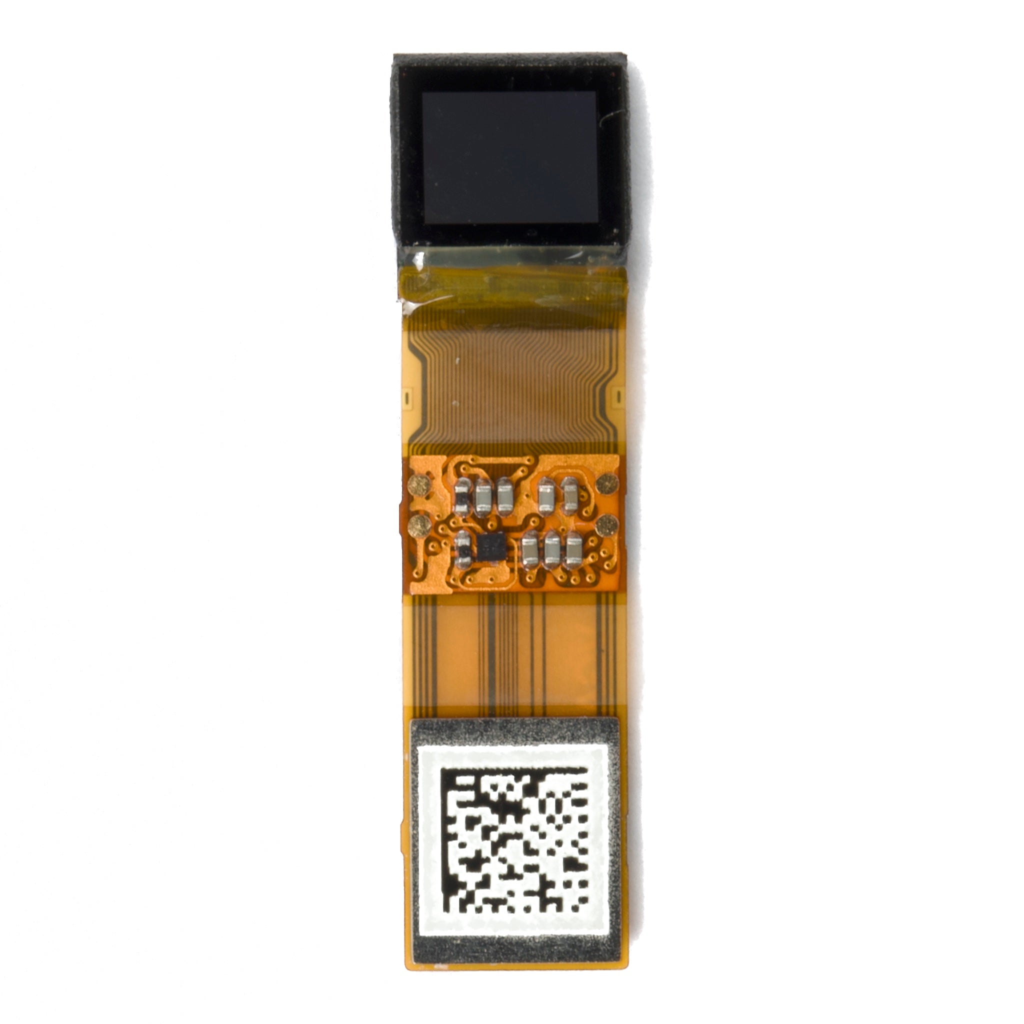
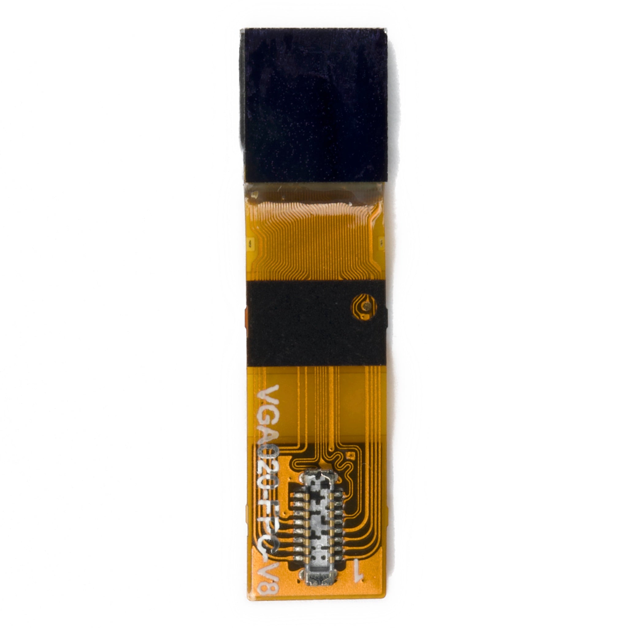
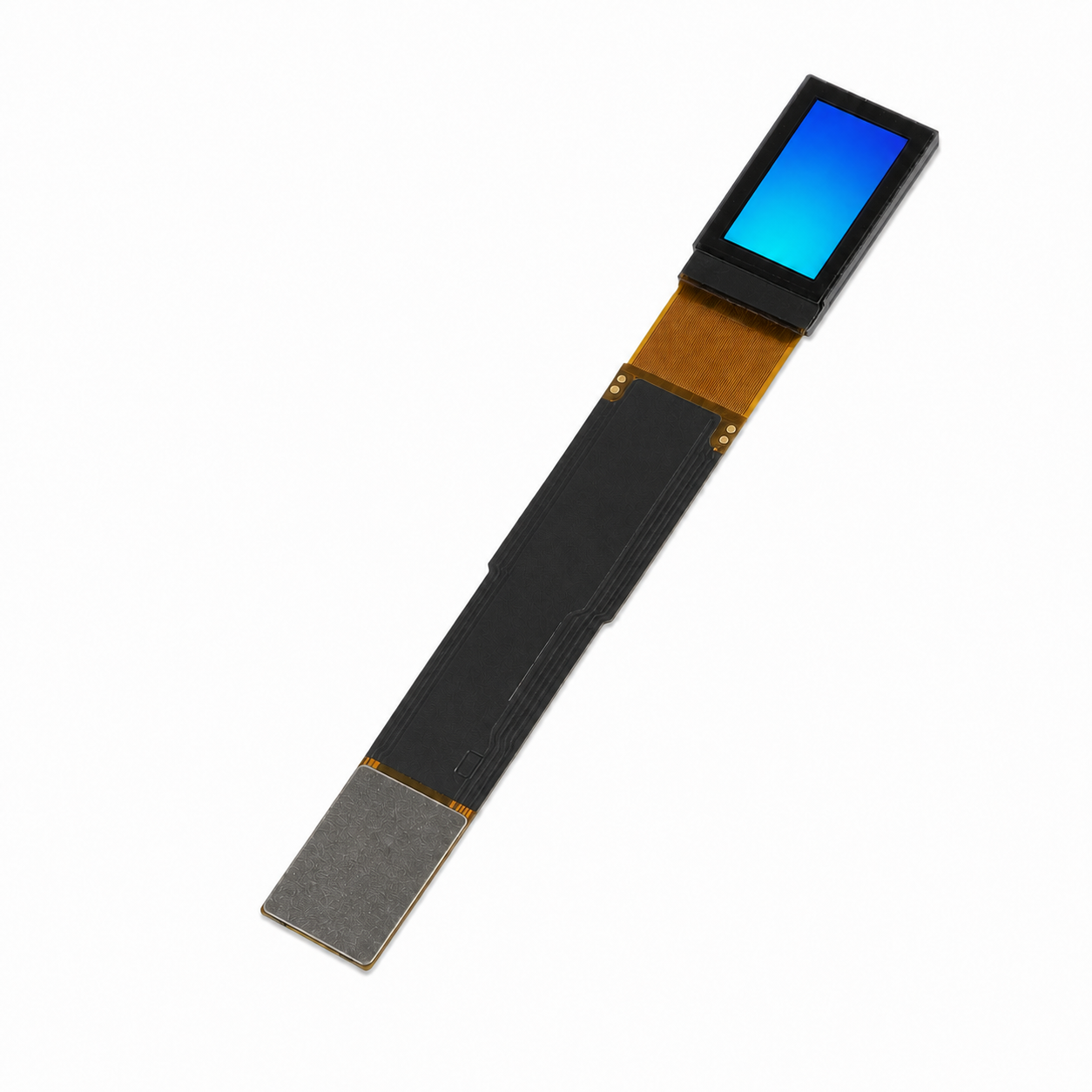
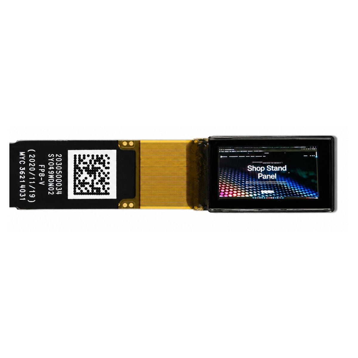
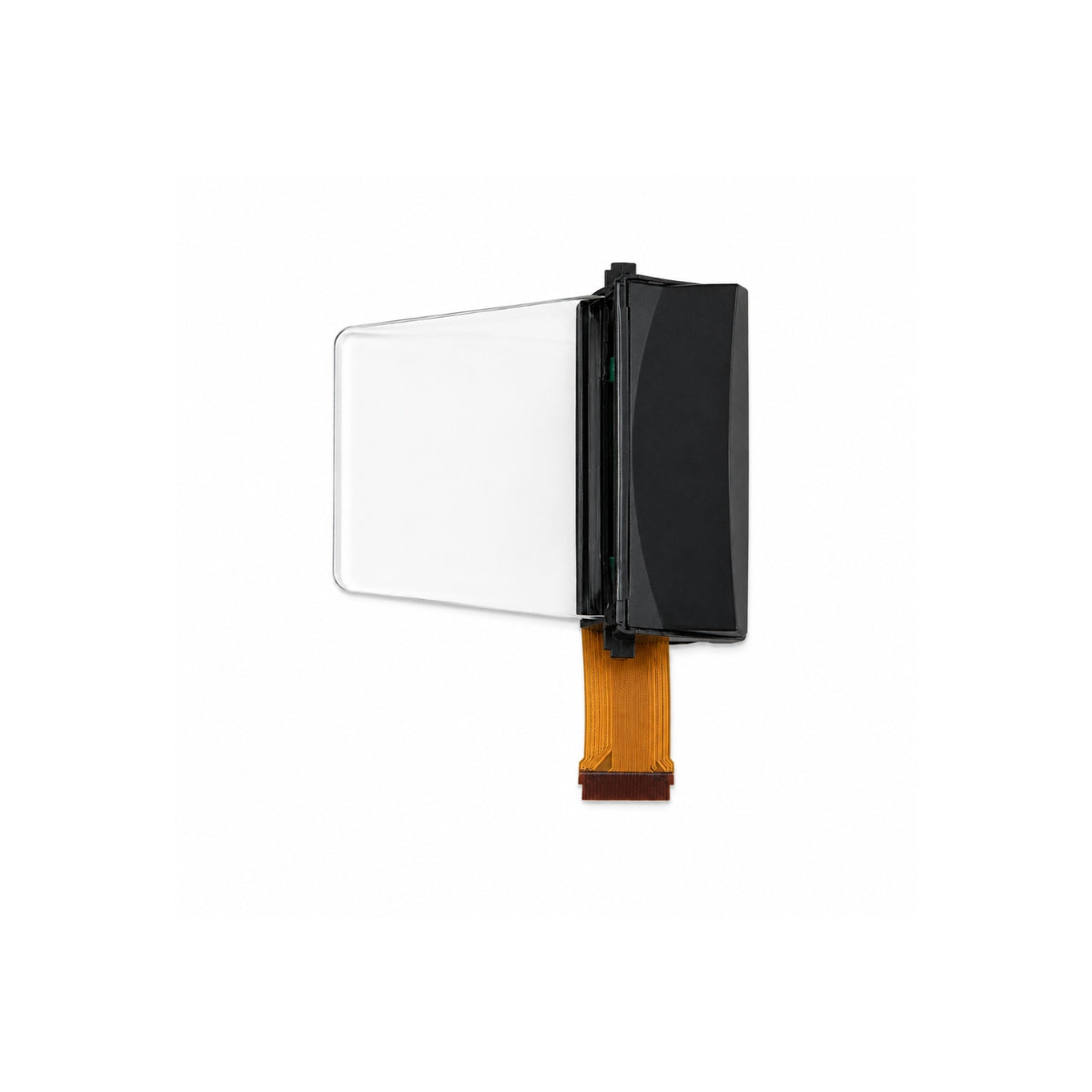
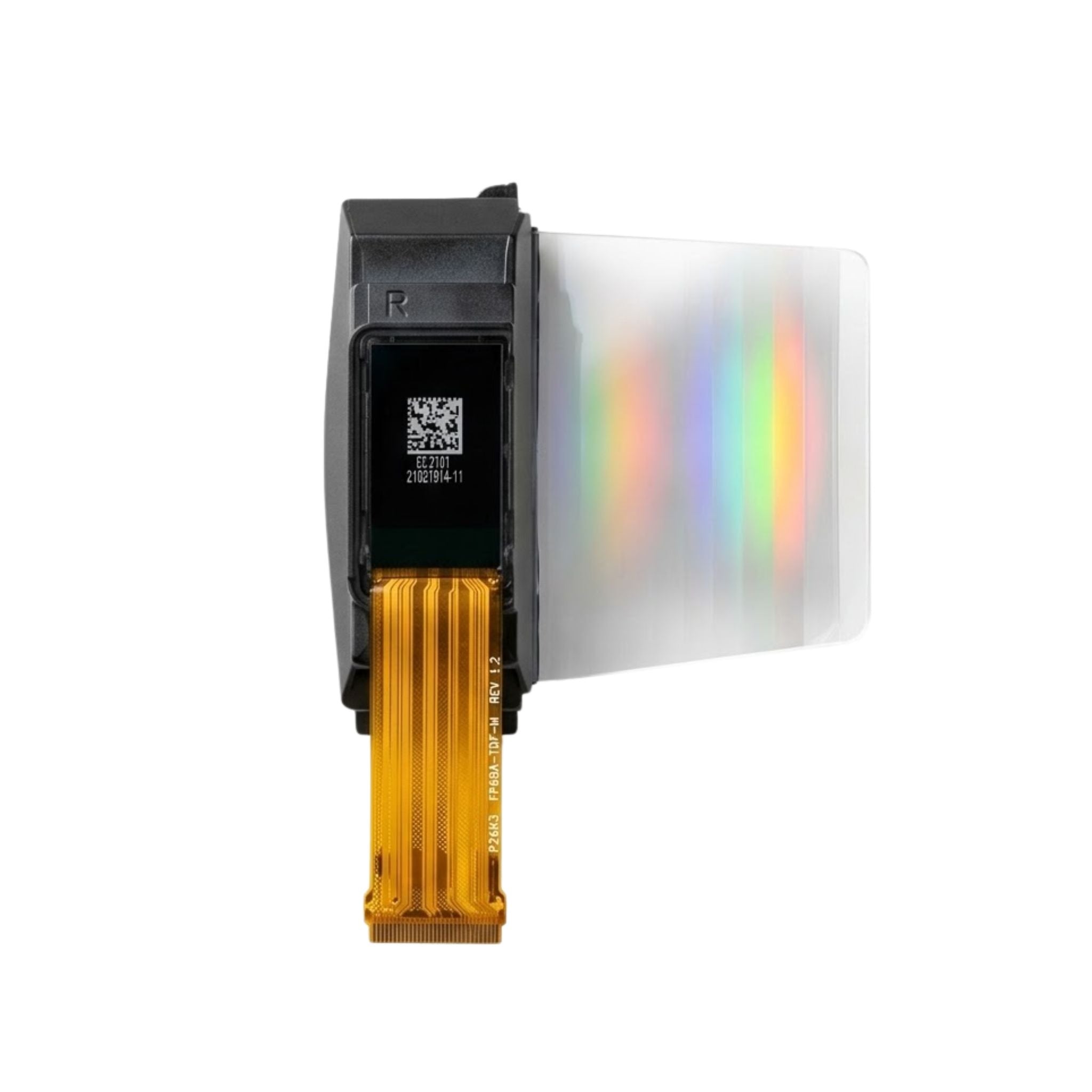


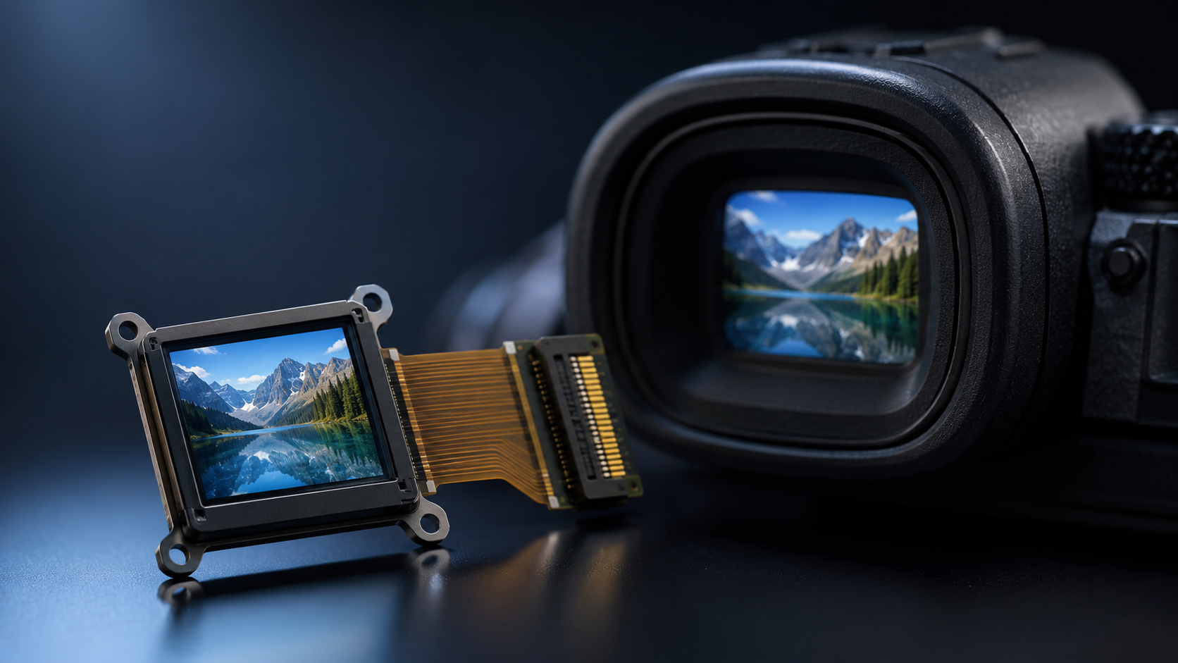
Micro OLED Module Supplier for EVF | High PPI, Fast Response, Compact Design
A Micro OLED module supplier for an electronic viewfinder has to do more than ship a high-PPI panel. It must match pixel density to the eyepiece, keep response fast enough for panning, prove brightness at the eye rather than on the datasheet, and hold optical alignment from sample to mass production. This guide covers the checks that separate a capable EVF partner from a catalogue reseller.
The Viewfinder Is an Unforgiving Display
An EVF image is magnified by an eyepiece and viewed from a couple of centimetres away. That magnification enlarges everything, including what you would rather not see: pixel structure, mura, colour shading across the field, and any misalignment between panel and optical axis.
The requirement set is therefore a four-way conflict. High pixel density, fast response, deep black in dim scenes and a display engine small enough to fit inside a camera housing all compete for the same volume and power. Micro OLED resolves that conflict better than most because the organic stack sits on a single-crystal silicon backplane, with drive circuits formed underneath the emitting area, so no backlight layer is needed.[2]

Pixel Density Only Means Something With Optics
PPI is a ratio, not a quality grade. It is the diagonal pixel count divided by the diagonal in inches, which is why the same resolution can be quoted at very different densities depending on the size class it is built into.
The arithmetic matters because buyers compare numbers from suppliers who measure differently. A 1920×1080 panel on a 0.6-inch diagonal works out near 3,670 PPI. The same 1920×1080 resolution spread over 0.83 inch falls to roughly 2,645 PPI. Neither figure says anything about perceived sharpness until the eyepiece magnification and field of view are known.
The useful metric is angular. Divide horizontal pixel count by horizontal field of view in degrees to estimate pixels per degree at the eye, then treat the result as an upper bound, because distortion correction, pre-distortion rendering and usable eye-box cropping all consume pixels near the edges.
When a supplier quotes density, ask for active area, pixel pitch and diagonal as a set. A pitch figure alone is not enough for mechanical design, and a diagonal figure alone will not tell your optical engineer whether the modulation transfer function of the eyepiece can actually resolve the pixel grid.
Response Speed Is Not the Same as Latency
OLED emission follows drive current closely, so pixel transition is fast compared with liquid-crystal switching under equivalent drive. That is a genuine advantage, but it is not what the photographer feels. What they feel is the delay between moving the camera and seeing the scene move.
Total latency is a chain: sensor readout, image processing, interface transport, driver timing, pixel response and optical persistence. A fast panel inside a slow pipeline still feels sluggish, and a modest panel inside a well-tuned pipeline can feel immediate. Ask for end-to-end measurements, not a panel-level response figure.
Refresh rate sets the floor on how often that chain can update. At 120 Hz a fresh frame becomes available a little over eight milliseconds after the previous one, so any processing stage that costs several frame periods dominates the budget. Suppliers should be able to state supported refresh modes, driver timing and interface bandwidth for the exact module, not for a panel family.
Brightness Has to Be Measured at the Eye
A luminance value taken at the panel surface describes the emitter, not the finder. Between panel and eye sit relay lenses, coatings, a dioptre mechanism and an exit pupil, and every element removes light on the way through.
Two suppliers can quote identical panel luminance and deliver visibly different finder brightness once their eyepieces are fitted. Require module-level data: luminance at the exit pupil, uniformity across the field, contrast under a stated ambient condition, and the measurement geometry behind each figure.
Contrast deserves the same scrutiny. OLED black is set by how little a pixel emits, which is very low, but perceived contrast in a finder also depends on reflections from lens surfaces and the housing interior. A strong panel contrast ratio can be flattened by a poorly coated eyepiece, and a supply specification that stops at the panel will not catch it.
What the Module Contains
| Block | Typical implementation | What it decides |
|---|---|---|
| Silicon backplane | CMOS active-matrix wafer with pixel drive circuits | Pixel pitch, uniformity, defect density |
| OLED stack | White emitter with colour filter, or RGB deposition | Efficiency, gamut, lifetime, achievable pitch |
| Encapsulation | Thin-film, glass frit or hybrid barrier | Humidity survival, shelf life, field reliability |
| Eyepiece | Aspheric relay optics with dioptre adjustment | Magnification, eye relief, distortion, perceived sharpness |
| Interface | MIPI DSI, LVDS or parallel RGB plus FPC | Bandwidth, cable length, EMI risk, bring-up effort |
Each row is a place where a supplier either differentiates or cuts corners, and each one can be interrogated with a specific question. A vendor that can only discuss the OLED stack is likely buying backplanes rather than designing them.
Validating Samples
Datasheet values are typical values, produced under one drive condition and one temperature. Production units spread around those typicals, and the spread is what your inspection plan has to absorb.
Pixel defect acceptance belongs in writing, with a named class and an inspection distance, because "no visible defects" is not a testable criterion. ISO 9241-307 sets out a framework for classifying pixel faults and defines the measurement conditions under which display characteristics are assessed.[1]
- Optical: luminance and chromaticity at several grey levels, field uniformity, contrast in a dark room, mura under grey ramps
- Electrical: power sequencing, initialisation, interface margin at maximum cable length, sleep and standby current
- Mechanical: optical centre position, tilt, FPC bend radius, connector retention after repeated mating
- Environmental: storage at high humidity, temperature cycling, and brightness drift after both
Test the module inside the actual eyepiece and the actual housing. Reflections, stray light and thermal rise only appear once the assembly is closed, and finding them at pilot build is expensive.
Supply Continuity and Change Control
Camera platforms live for years and share modules across several bodies. A supplier that cannot describe its end-of-life policy is a scheduling risk, however good the sample was.
Ask for the critical-material list, the single-source items, and the notification window for process or material changes. OLED is unusually sensitive here: a new host material, a different encapsulation adhesive or a revised driver setting can shift brightness, colour point and lifetime without changing the part number.
Require advance notice plus requalification for any change that touches the emitting stack, the barrier or the driver configuration. A last-time-buy option and a documented PCN process are worth more than a small price concession on the first order.
Customization That Changes the Outcome
Most EVF projects need some level of customisation, and the highest-value work usually happens before the first sample exists: feasibility review, optical-electrical trade-off analysis, and an honest statement of which targets cannot be met together.
Practical customisation covers eyepiece prescription and optical centre tolerance, FPC shape and connector position, gamma and white-point tables, brightness control curve, and thermal path through the housing. Interface tuning at realistic cable length is often the difference between a clean bring-up and a month of signal-integrity debugging.
For broader module options across sizes and interfaces, see the Micro OLED collection, and for head-mounted and viewfinder product contexts see the AR and VR display collection.
Choosing the Partner
Score suppliers on four questions: can they explain the optical consequence of each panel parameter, can they show module-level measured data, can they document change control, and can they support the module for the life of the platform. The vendor that answers all four is worth a longer lead time than the one that only wins on price per unit.
References
- ISO 9241-307:2008 — Ergonomics of human-system interaction — Part 307: Analysis and compliance test methods for electronic visual displays. International Organization for Standardization. https://www.iso.org/standard/40102.html
- Hilsum, C. (2010). Flat-panel electronic displays: a triumph of physics, chemistry and engineering. Philosophical Transactions of the Royal Society A, 368(1914), 1027–1082. https://doi.org/10.1098/rsta.2009.0247
En lire plus
The rapid development of smart glasses, AR headsets, MR devices, and other near-eye optical products is reshaping the microdisplay market. OLEDOS, also.
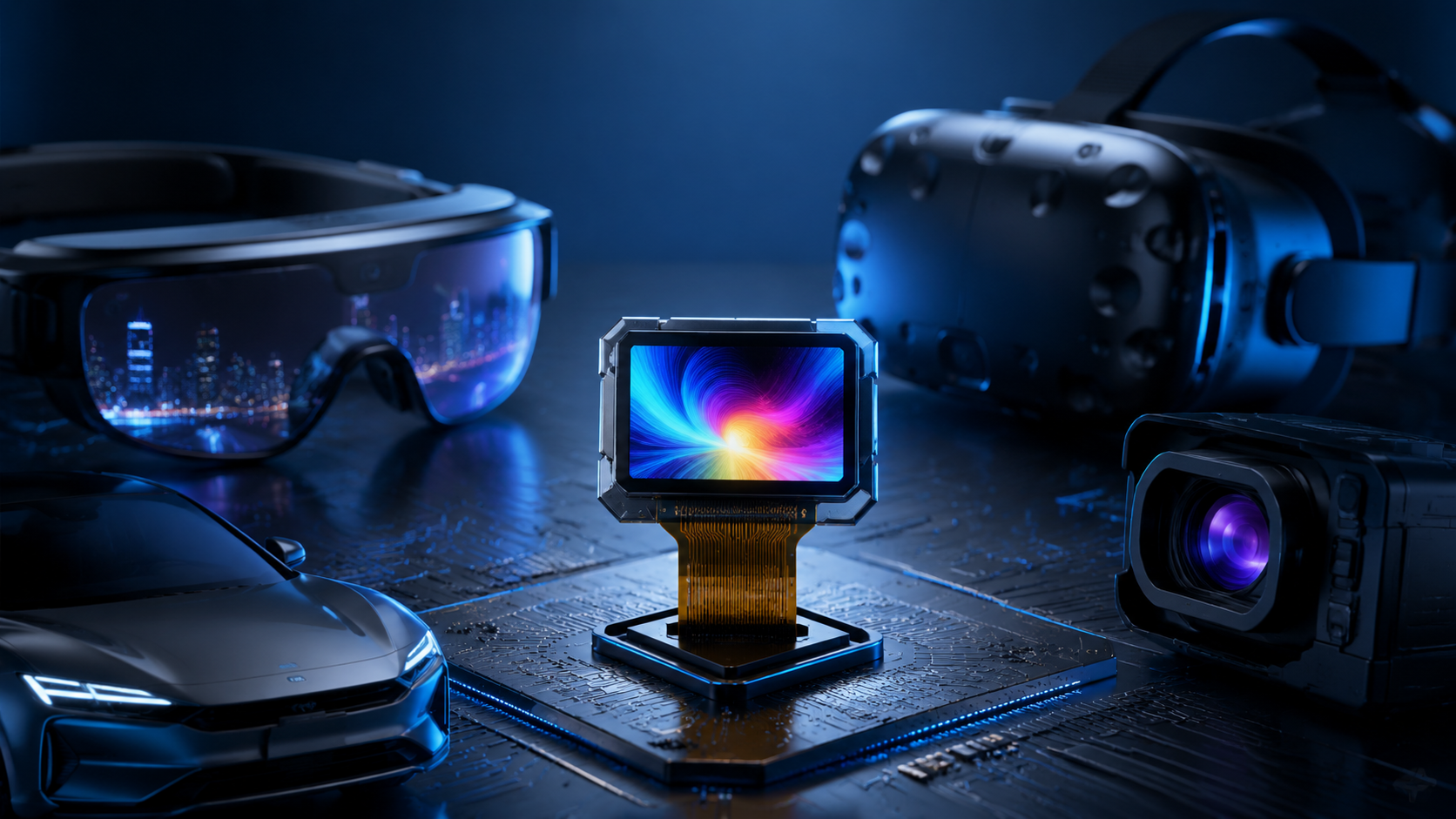
Micro OLED displays, also known as OLED-on-Silicon displays, combine high pixel density, fast response, high contrast, compact size, and efficient power.
Laisser un commentaire
Ce site est protégé par hCaptcha, et la Politique de confidentialité et les Conditions de service de hCaptcha s’appliquent.