









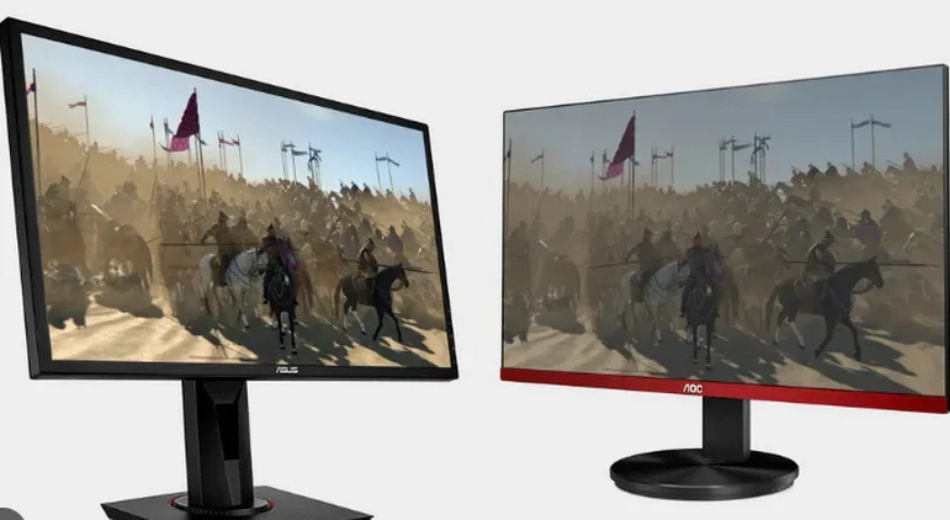
TFT LCD vs IPS LCD | Key Differences, Response Time & Color Accuracy
The two terms are not alternatives. TFT LCD describes the switching backplane—a thin-film transistor at every pixel—while IPS describes how the liquid crystal inside that pixel is arranged and driven. Almost every IPS panel is a TFT LCD, and so is a TN panel. The practical comparison is TN-TFT against IPS-TFT, and it turns on viewing angle, response behaviour and colour stability rather than on two unrelated technologies.
Two terms, one panel
A TFT LCD is defined by its active matrix. Each pixel owns a transistor that gates charge onto the pixel electrode, and a storage capacitor holds that charge for the rest of the frame. The transistor is a switch, not a light source; the liquid crystal modulates light that the backlight supplies.
IPS sits one level down, in the electrode layout. Pixel and common electrodes share the same glass substrate, so the field runs roughly parallel to the glass and rotates the molecules within their plane instead of tilting them upright. That single change carries most of the differences engineers care about.
How the molecules move
In a twisted nematic cell the molecules are aligned in a 90-degree twist between the two substrates. With no field, polarised light follows the twist and passes the front polariser; with a field, the molecules stand up and the cell goes dark. The motion is a tilt, and the tilt is what makes TN quick.
In an IPS cell the molecules start parallel to the glass and rotate in the plane. The motion is a shear, opposed by the viscosity of neighbouring molecules, and the field reaches the top of the cell only weakly because both electrodes sit at the bottom. Early IPS designs in the literature needed noticeably more drive voltage and time than TN for this reason;[2] modern architectures vary, and some use fringe-field switching to soften the trade-off.
| Property | TN-TFT | IPS-TFT | What it changes |
|---|---|---|---|
| Electrode placement | One electrode on each substrate | Both electrodes on the TFT substrate | Field direction, drive voltage |
| Molecular motion | Tilt out of plane | Rotation in plane | Switching speed, angle symmetry |
| Typical source driver | Often 6-bit with FRC | Commonly 8-bit, 10-bit on some parts | Gradient smoothness |
| Aperture ratio | Higher | Lower | Backlight current for a given luminance |
Viewing angle
IPS reduces the angle dependence of the cell; it does not remove it. The optical path through the liquid crystal, and the retardation it produces, still change as the eye moves off axis, and the polarisers are not perfectly angle-independent either.[1]
What changes most is symmetry. A TN cell is designed around one viewing direction, and contrast falls away quickly on the opposite side, which is why greyscale inversion appears when the panel is viewed from below. An IPS cell behaves more evenly left to right because the molecules rotate rather than tilt.
Compensation films matter as much as the electrode design. Retardation films laminated to the cell cancel part of the residual path difference at angle, so a low-cost IPS module with a thin film stack can look worse off axis than a well-compensated TN part. Datasheet viewing angles, commonly quoted as 178 degrees, describe the angle at which contrast falls to a defined ratio—not the angle at which colour is unchanged.

Response time
Historically the tilt of a TN cell switched faster than the shear of an IPS cell. Modern parts do not follow that rule automatically. The result depends on the liquid crystal mixture, the cell gap, the driving scheme and whether overdrive is applied, so a generation-old assumption is a poor basis for a specification.
Two measurement notes matter when reading datasheets. Grey-to-grey figures describe one specific transition, and the 10–90% rise is usually faster than the 90–10% decay. A part quoted at a few milliseconds for a mid-grey transition can still take considerably longer returning from black, because relaxation without a field is not driven.
For a static HMI or instrument panel, response time is rarely the constraint. For scrolling waveforms or a moving cursor it is. The useful figure is the worst-case transition at the temperature the product actually runs at, not the headline number measured at 25 °C.
Colour accuracy
Bit depth sets the starting point. TN panels are commonly 6-bit with frame rate control to emulate 8-bit, while IPS panels more often carry a native 8-bit source driver, with 10-bit available on some parts. FRC is a temporal and spatial dither: it holds up on still images and becomes more visible on moving edges and fine gradients.
Gamut is a separate property and belongs mostly to the backlight and the colour filter, not to the switching mode. A wide-gamut LED with a phosphor conversion layer will produce a wide gamut on either cell. The IPS advantage is stability—because the cell is closer to symmetric, hue and gamma shift less with angle, so a colour measured at the centre holds toward the corners of a larger panel.
Delta E figures only mean something with the conditions attached: instrument type, white point, luminance, patch size, and whether the unit was calibrated. A claim of Delta E below 2 on a calibrated sample says nothing about an uncalibrated module inside a metal housing.
Contrast and backlight
Native contrast comes from the liquid crystal cell and the optical stack, not from the backlight. Raising the backlight lifts white and black together, so the ratio stays roughly the same while the panel gets brighter and hotter.
IPS cells have a lower aperture ratio than TN cells because comb electrodes and the black matrix cover part of each sub-pixel. For the same luminance that means more backlight current and more heat, which is why an IPS module in a sealed enclosure needs its thermal path designed rather than assumed.
The off-axis dark state is the other trade-off. IPS panels show a bluish or purplish glow on a black field at wide angles, caused by the wavelength dependence of the residual retardation. It is a viewing-angle artefact, not a uniformity defect, and it does not appear on axis.
Choosing for a product
Choose TN when the eye is on axis, the cost target is tight, and the content is simple—fixed segments, basic text, a knob display. Choose IPS when two or more people look at the same screen, when the panel sits at an angle inside a housing, or when the image carries colour a user will judge.
Check the module, not only the glass: interface (RGB, LVDS, MIPI, SPI), operating temperature with the backlight included, touch bonding, and whether the supplier publishes the conditions behind each number. Standard configurations are listed under TFT LCD modules and IPS display modules, with wide-temperature versions under industrial displays.
References
- ISO 9241-307:2008 — Ergonomics of human-system interaction — Part 307: Analysis and compliance test methods for electronic visual displays. International Organization for Standardization. https://www.iso.org/standard/40102.html
- Hilsum, C. (2010). Flat-panel electronic displays: a triumph of physics, chemistry and engineering. Philosophical Transactions of the Royal Society A, 368(1914), 1027–1082. https://doi.org/10.1098/rsta.2009.0247
En lire plus
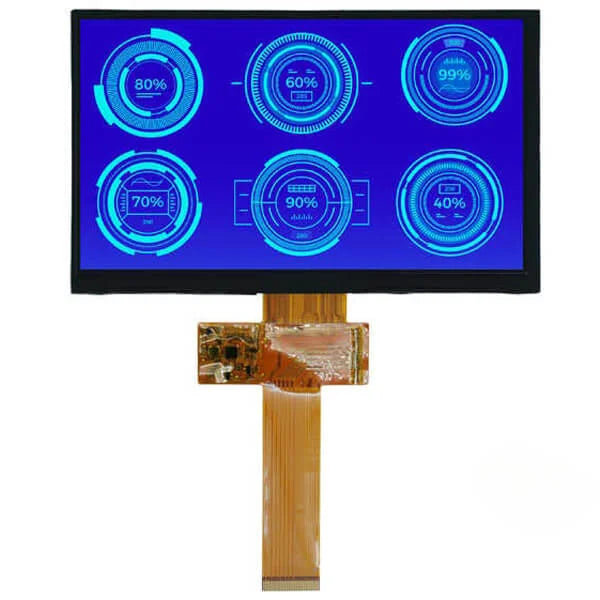
For industrial TFTs, choose a sunlight-readable IPS panel with brightness above 1000 nits, an operating temperature of -30 to 85°C, and a backlight.

It is recommended to control the brightness at 50% to reduce backlight loss and extend the lifespan to 50,000 hours; Maintain a room temperature of 25°C.
Laisser un commentaire
Ce site est protégé par hCaptcha, et la Politique de confidentialité et les Conditions de service de hCaptcha s’appliquent.