









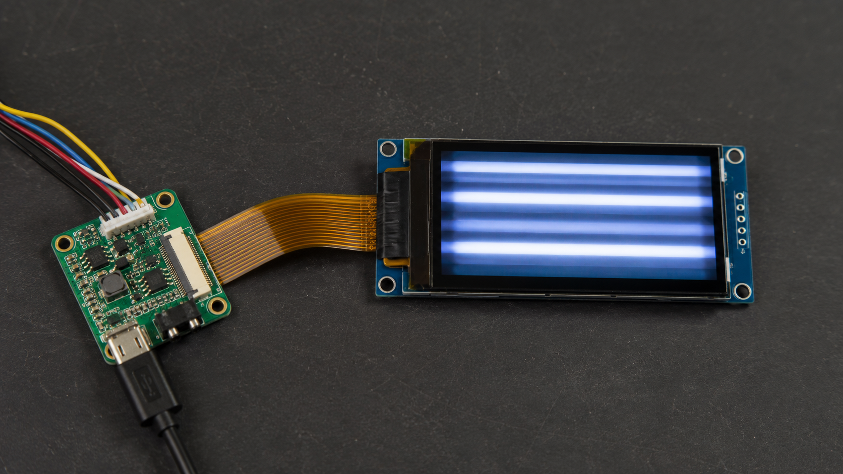
Why Does a PMOLED Display Have Uneven Brightness Between Rows?
A PMOLED panel that shows some rows brighter than others is almost always telling you one of four things: the multiplex ratio does not match the panel, the pre-charge or drive timing is wrong, the supply is sagging under peak current, or the COM/SEG wiring does not match the firmware's mapping. Brightness differences that follow the row structure are a drive-domain symptom, not a panel defect — which makes them diagnosable in a fixed order.
How row scanning creates the possibility of uneven rows
A passive matrix lights one row at a time. With N rows, each row is on for one Nth of the frame, so the instantaneous current must be roughly N times the desired average. Any difference in the time a row is on, or in the current it receives during that time, shows up directly as a brightness difference.
That is why the symptom localises to rows. A panel defect usually produces a spot, a line or a region; a drive-domain problem produces a pattern that repeats with the row structure or the frame.
First, classify what you are looking at
Photograph the panel in a dark room at fixed exposure, then answer three questions in order. Is the difference per row, per column, or across the whole panel as a gradient? Is it stable, or does it change with content? Does it move if you scroll the image by one row?
Those answers separate the four causes before any instrument is needed. A per-row pattern that stays with the row index points at the drive timing or the mapping. A pattern that moves with the content points at the image data or the pre-charge. A gradient across the panel points at supply drop or electrode resistance.
Reading the defect pattern
| Observation | Most likely cause | First check |
|---|---|---|
| The first row after a long blank region is dim | Insufficient pre-charge | Pre-charge voltage and clock timing |
| Every Nth row is dim, evenly spaced | Multiplex ratio mismatch | Firmware's MUX setting against the panel's row count |
| The whole panel is dim and uneven, worse at one edge | Supply sag under peak current | VCC and boost headroom at maximum on-pixels |
| Rows appear shifted or duplicated | COM/SEG mapping error | Init sequence versus the panel's COM assignment |
| Brightness differs between frames of the same image | Frame timing or refresh instability | Frame rate and the display task's timing jitter |
Check the multiplex ratio first
The controller's multiplex ratio must equal the panel's row count. If firmware drives 64 rows while the panel has 32, half the rows are never lit and the rest are driven at the wrong duty; if it drives fewer rows than exist, brightness rises and lifetime shortens. Both mistakes present as brightness that is wrong everywhere, with a pattern that follows the row index.
This is the most common cause of "uneven rows" in custom designs, because the multiplex setting lives in an initialisation table that is often copied between projects.
Check pre-charge and ghosting
Passive matrix pixels need to be brought to their target voltage within a row's time slot. Pre-charge shortens that settling time by applying a defined voltage before the data phase. Too little pre-charge leaves rows that follow a dark region short of their target — the classic symptom is the first row after a blank area appearing dim.
Too much pre-charge, or a pre-charge level close to the data level, produces the opposite artefact: faint illumination in pixels that should be off, visible as vertical ghosting.
Check supply headroom and electrode drop
Peak current in a passive matrix occurs when many pixels in a row are lit simultaneously. If the boost converter or the decoupling cannot supply that peak, the row voltage sags, and the sag deepens as more pixels turn on. The symptom is a panel that looks acceptable on sparse content and uneven on full-white content, often with the far edge from the supply rail dimmer.
Two fixes exist: add decoupling close to the driver and verify the boost's transient response at worst-case load, or reduce peak demand by lowering brightness or splitting the display update across frames.
Check COM/SEG mapping and init order
A mapping error usually produces a scrambled image rather than uniform brightness, but a partially wrong mapping — where COM pins are assigned in a different order than the panel expects — can look like a repeating brightness difference because rows are being driven with data intended for other rows. Comparing the initialisation sequence against the panel's datasheet, pin by pin, resolves it.
Confirming the timing with an oscilloscope
Firmware settings can be checked on paper, but the timing that actually reaches the panel needs a scope. Probe the row clock and one COM output, then measure three things: the row period against the expected frame time divided by the row count, the pre-charge window inside each row, and the settling of the segment voltage before the row clock falls.
Two signatures are diagnostic. If the segment voltage is still rising when the row clock drops, the pre-charge window is too short or the drive current is too low for the panel's capacitance — the row never reaches its target and appears dim. If the segment voltage overshoots and then decays, the pre-charge level is too high or the discharge path is insufficient, which produces ghosting in the following row.
Recording the same measurement with a full-white image and with sparse content separates supply problems from timing problems: if the waveform only sags with heavy content, the fault is in the supply's transient response, not in the display timing.
Firmware or hardware
The split matters for cost. Multiplex ratio, pre-charge, frame timing and mapping are firmware fixes. Supply sag and electrode drop are hardware fixes — decoupling, boost sizing, or a design change if the panel is simply too large for the chosen structure. Diagnose in the order above, because the firmware checks are free and the hardware ones are not.
PMOLED modules and their controllers are listed in the PMOLED display collection, with character formats under character OLED displays. Luminance and uniformity figures should be requested with their measurement basis, standardised in ISO 9241-307[1].

Uneven brightness between rows on a PMOLED is a drive problem, not a panel defect, in the overwhelming majority of cases. Check multiplex ratio against row count, then pre-charge timing, then supply headroom, then COM mapping — and decide early whether the fix lands in firmware or in hardware.
References
- ISO 9241-307:2008 — Ergonomics of human-system interaction — Part 307: Analysis and compliance test methods for electronic visual displays. International Organization for Standardization. https://www.iso.org/standard/40102.html
En lire plus
A TFT LCD usually resets when brightness is increased because the backlight draws more power and causes the supply voltage to drop. Other possible causes.
An I2C OLED usually stops responding after repeated sleep cycles because one sleep or wake event leaves the bus, MCU peripheral, GPIO pins or OLED.
Laisser un commentaire
Ce site est protégé par hCaptcha, et la Politique de confidentialité et les Conditions de service de hCaptcha s’appliquent.