









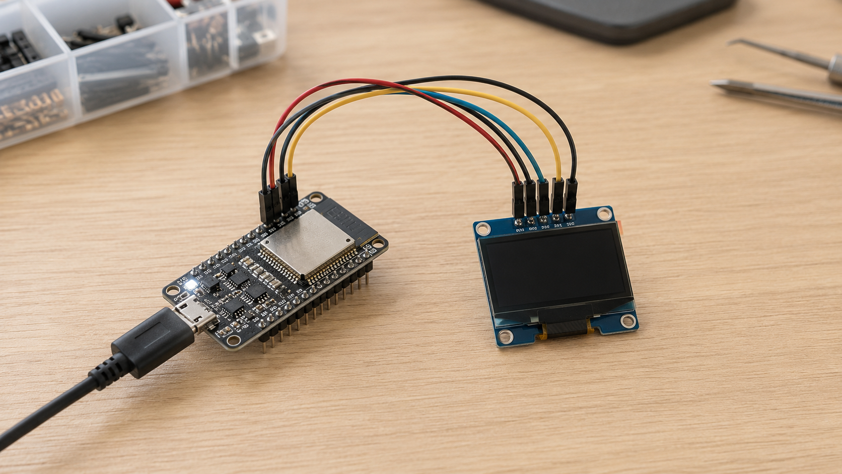
An I2C OLED usually stops responding after repeated sleep cycles because one sleep or wake event leaves the bus, MCU peripheral, GPIO pins or OLED controller in the wrong state. The MCU may sleep before a transfer ends, the final STOP condition may be missing, SDA may remain low, or the OLED may lose power and wake without full initialization.
Start by checking three things before resetting the board: whether the OLED still acknowledges its I2C address, whether SDA and SCL are high, and whether the OLED stayed powered during sleep. These checks quickly separate a display-setting problem from a bus, MCU or power problem.

Identify the Fault
A black screen does not always mean that I2C communication has failed. The OLED may still accept commands while its charge pump, addressing mode, display window or frame data is wrong.
Record the failed state before the watchdog or recovery code changes it. Check:
- OLED supply voltage
- OLED reset-pin level
- SDA and SCL voltage
- MCU I2C busy and error flags
- OLED address ACK or NACK
| Observed State | Likely Problem | First Action |
|---|---|---|
| OLED acknowledges, but the screen is black | Display-off state, lost settings or missing redraw | Run full initialization and send a complete frame |
| No acknowledgment and SDA is low | Stuck bus or a target waiting for more clocks | Stop all transfers and run bus recovery |
| No acknowledgment, but SDA and SCL are high | Power, reset, address, GPIO or startup timing | Measure OLED power and reset timing |
| SCL stays low | MCU pin error, another device, level shifter or short | Disable MCU I2C and check SCL again |
An address acknowledgment proves only that one short transaction worked. It does not prove that the charge pump is enabled, the address window is correct or a full-frame transfer is reliable.
Also check whether the software expects a 7-bit or 8-bit address. Many OLED modules use the 7-bit address 0x3C, while some documents show 0x78 as the full write-address byte. Passing 0x78 to an API that expects a 7-bit address will fail.
The display module interface guide explains common display interfaces and address handling in more detail.
Know What Sleeps
The correct wake process depends on what was actually turned off.
Display-off mode: The OLED controller remains powered, but panel output is disabled. On an SSD1306-type controller, 0xAE turns display output off and 0xAF turns it on. If power and reset remain stable, display RAM and controller settings may remain available.
MCU sleep: The OLED stays powered, but the microcontroller stops clocks or disables peripherals. The OLED may keep its image while the MCU loses GPIO, I2C, DMA or interrupt settings.
OLED power-off: The OLED supply is physically removed. After power returns, treat the controller as uninitialized. Sending only 0xAF is not enough.
Full system power loss: Both the MCU and OLED lose power. The system must use a cold-start sequence.
A controller datasheet describes the controller IC. A finished module may also contain capacitors, pull-up resistors, a regulator, level shifting or a reset circuit. These parts can change the real startup and shutdown time.
For battery-powered products, compare command-based sleep with complete power gating. The display power-consumption guide explains the difference between active, standby and powered-off states.
Calculate the Transfer Time
The most common failure is entering sleep while the OLED is still receiving data.
Many display libraries use DMA, interrupts or a background task. A display function may return after placing data into a queue even though the physical I2C transfer is still running.
This sequence is unsafe:
oled_display_off();
enter_deep_sleep();
A monochrome OLED normally uses one bit per pixel. The full-frame data size is:
Frame bytes = width × height ÷ 8| Resolution | Frame Data | Minimum Time at 400 kHz | Minimum Time at 100 kHz |
|---|---|---|---|
| 64 × 48 | 384 bytes | 8.64 ms | 34.56 ms |
| 128 × 32 | 512 bytes | 11.52 ms | 46.08 ms |
| 96 × 64 | 768 bytes | 17.28 ms | 69.12 ms |
| 128 × 64 | 1024 bytes | 23.04 ms | 92.16 ms |
These values include eight data bits and one ACK bit for each byte. They do not include the target address, control bytes, commands, repeated START conditions or software delays.
A library that divides one frame into many short transactions can take noticeably longer than the table shows. This is why a fixed 1 ms or 5 ms delay may work after a short command but fail during a complete screen update.
A practical starting point for software timeouts is:
| Transfer Type | Suggested Starting Timeout |
|---|---|
| Short command transaction | 5–20 ms |
| 128 × 64 frame at 400 kHz | 30–50 ms |
| 128 × 64 frame at 100 kHz | 100–150 ms |
These are engineering starting points, not fixed I2C requirements. Measure the real transfer time produced by the MCU, library and display module before choosing the final timeout.
A compact 0.96-inch 128 × 64 OLED module may support both I2C and SPI. I2C uses fewer pins, but its longer frame time makes transfer control more important before sleep. See the SPI and I2C comparison for interface differences.
Finish I2C Before Sleep
Wait for the physical transaction to finish before disabling clocks, DMA or OLED power.
block_new_oled_updates();
stop_display_refresh_timer();
acquire_i2c_bus_lock();

if (!wait_for_current_i2c_transfer(I2C_TIMEOUT_MS)) {
    abort_i2c_transfer();
    reset_i2c_peripheral();
}

send_oled_command(0xAE);

if (!wait_for_i2c_stop(I2C_TIMEOUT_MS)) {
    abort_i2c_transfer();
    reset_i2c_peripheral();
}

clear_i2c_error_flags();
disable_i2c_dma_and_interrupts();

release_i2c_bus_lock();
enter_deep_sleep();
This is generic pseudocode. Replace the function names with the correct API calls for the MCU and display driver.
DMA completion does not always mean that the wire transfer has ended. On some MCUs, DMA finishes when the last byte enters the I2C peripheral. The peripheral still needs time to transmit that byte and generate STOP.
Confirm both the driver’s transfer-complete event and the I2C STOP or bus-idle state.
Check the STOP Condition
An I2C STOP occurs when SDA changes from low to high while SCL is high.
A normal OLED command should appear as:
START
OLED address
ACK
Control byte
ACK
Command byte
ACK
STOP
If the trace ends after an ACK or in the middle of a byte, the transfer was interrupted. The OLED may still be waiting for another bit, while the MCU may keep its I2C busy flag set.
Recover a Stuck Bus
SDA and SCL should both be high when the bus is idle.
If SDA stays low, the OLED or another target may be waiting to finish a byte. The MCU pin may also be configured as output-low, or an unpowered device may be loading the line.
The normal bus-clear method sends up to nine SCL pulses. This gives a target enough clocks to finish the current byte and release SDA.
Run bus recovery only when:
- No valid transaction is running.
- All OLED updates have stopped.
- The MCU owns the bus.
- SCL can return high.
- SDA and SCL are open-drain GPIOs.
bool recover_i2c_bus(void)
{
    disable_i2c_peripheral();

    configure_open_drain_gpio(SCL_PIN);
    configure_open_drain_gpio(SDA_PIN);

    release_line(SCL_PIN);
    release_line(SDA_PIN);
    delay_us(5);

    if (!read_line(SCL_PIN)) {
        return false;
    }

    for (int pulse = 0; pulse < 9; pulse++) {
        if (read_line(SDA_PIN)) {
            break;
        }

        drive_line_low(SCL_PIN);
        delay_us(5);

        release_line(SCL_PIN);
        delay_us(5);

        if (!read_line(SCL_PIN)) {
            return false;
        }
    }

    if (!read_line(SDA_PIN)) {
        return false;
    }

    /* Generate STOP: SDA rises while SCL is high. */
    drive_line_low(SDA_PIN);
    delay_us(5);

    release_line(SCL_PIN);
    delay_us(5);

    release_line(SDA_PIN);
    delay_us(5);

    restore_i2c_pin_function();
    reset_i2c_peripheral();
    initialize_i2c_peripheral();

    return read_line(SDA_PIN) && read_line(SCL_PIN);
}
Never drive SDA or SCL high with a push-pull output. Release the line and let the pull-up resistor raise it.
Nine clocks are one recovery attempt, not a repair that should run forever. If SDA remains low, reset or power-cycle the device holding it.
If SCL stays low, clock recovery cannot run. Disable the MCU I2C peripheral and set SCL to a high-impedance input. If SCL rises, the MCU configuration caused the problem. If it stays low, another device, a level shifter or a short is holding the line.
Restore MCU Hardware
The physical bus may be idle while the MCU still reports I2C busy. This happens when the internal state machine was stopped during a transfer.
After deep sleep, restore the hardware in this order:
Enable GPIO clock
Restore SDA and SCL pin multiplexing
Set both pins to open-drain mode
Restore the pull-up arrangement
Enable the I2C peripheral clock
Reset the I2C hardware block
Clear error and STOP flags
Load the I2C timing settings
Enable DMA or interrupts
Check SDA and SCL
Probe the OLED address
Do not rely only on a software flag such as i2c_initialized = true. The object may remain in RAM even though the hardware clock, pins or state machine has been reset.
Internal MCU pull-ups are often weak and may be disabled during deep sleep. They should not automatically replace suitable external I2C pull-ups.
Fix Power Timing
The MCU may wake faster than the OLED supply or reset circuit.
If the MCU sends the first address while OLED power is still rising, the display may return NACK. Some drivers then stop using the display instead of retrying.
Measure these signals together:
- OLED power-enable signal
- OLED supply voltage
- OLED reset pin
- SCL
- SDA
Check whether power is stable before reset is released and whether the first I2C START occurs after reset. Repeat the test at minimum battery voltage and low temperature, where startup may be slower.
oled_power_on();
delay_ms(MEASURED_POWER_RISE_TIME);

oled_reset_low();
delay_us(REQUIRED_RESET_LOW_TIME);
oled_reset_high();

delay_ms(MEASURED_RESET_RELEASE_TIME);

restore_i2c_gpio_and_clocks();
reset_and_initialize_i2c();
initialize_oled();
Use the exact module requirements and measured waveforms to choose the delays. Do not add one large delay without knowing which signal needs more time.
Check Power-Off
Turning off the OLED power switch does not mean that its supply immediately reaches zero volts.
Module capacitors may keep the controller partly powered. The voltage can be too low for normal operation but still too high to cause a clean power-on reset.
Use a simple stepped test:
| Test Off-Time | What It Shows |
|---|---|
| 10 ms | Checks whether very short power gating leaves the module partly powered |
| 50 ms | Checks whether extra discharge time improves recovery |
| 100 ms | Helps confirm a slow-discharge or incomplete-reset problem |
These values are diagnostic steps, not universal OLED requirements. Measure the real rail voltage during each test.
If longer off-time improves reliability, possible fixes include:
- Allow more measured discharge time.
- Add a suitable discharge resistor.
- Use a load switch with output discharge.
- Pulse the OLED reset pin after power returns.
- Keep the controller powered and use display-off mode instead.
Stop Back-Power
An unpowered OLED may receive current through SDA or SCL when the MCU and bus pull-ups remain powered. Whether this happens depends on the controller, module circuit and level shifter.
Common signs include:
- OLED VCC remains above zero after its supply is switched off.
- Standby current is higher than expected.
- SDA becomes stuck after repeated power cycles.
- The display recovers only after the whole board is disconnected from power.
Turn off OLED power and measure VCC, SDA and SCL. Then set the MCU pins to high impedance. If OLED VCC falls further, the interface may be feeding the module.
Possible solutions include:
- Move the pull-ups to the correct switched rail.
- Set SDA and SCL to high impedance before power-off.
- Disable the level shifter before removing OLED power.
- Use an I2C bus switch between separate power domains.
Check all devices sharing the bus before moving the pull-ups. The change may also affect sensors and other targets.
Use the Right Wake Path
A display-on command does not rebuild all OLED settings after power loss or reset.
A cold initialization may need to restore:
- Multiplex ratio
- Display offset and start line
- Segment and COM scan direction
- Memory addressing mode
- Clock and pre-charge settings
- VCOM level
- Contrast
- Charge-pump settings
- Display-on state
Use a light wake only when the OLED stayed powered and was not reset:
bool oled_light_wake(void)
{
    restore_i2c_gpio_and_clocks();

    if (!physical_bus_is_idle()) {
        if (!recover_i2c_bus()) {
            return false;
        }
    }

    reset_and_initialize_i2c();

    return send_oled_command(0xAF);
}
Use a cold wake after power loss, reset, brownout or an unknown state:
bool oled_cold_wake(void)
{
    oled_power_on();
    delay_ms(POWER_RISE_DELAY);

    pulse_oled_reset();
    delay_ms(RESET_RELEASE_DELAY);

    restore_i2c_gpio_and_clocks();

    if (!physical_bus_is_idle()) {
        if (!recover_i2c_bus()) {
            return false;
        }
    }

    reset_and_initialize_i2c();

    if (!send_complete_oled_initialization()) {
        return false;
    }

    reset_display_address_window();
    redraw_complete_frame();

    return true;
}
Choose the wake path from the real power and reset state, not from a saved software flag.
Keep States in Sync
Three states must agree:
- The image stored in the MCU frame buffer
- The page, column and mode stored by the display library
- The real registers and display RAM inside the OLED
If the OLED resets while the library stays in RAM, the library may believe that horizontal addressing is active even though the controller has returned to another mode. The OLED can acknowledge data but place it in the wrong memory location.
After an uncertain reset, reset the I2C driver and display-library state, send the full initialization sequence, restore the address window and redraw the full frame. Do not begin with a partial update.
Prevent Task Races
The fault can occur when a display task, timer, DMA callback or interrupt starts a transfer while the power code is preparing to sleep.
A typical failure is:
- The power task checks that I2C is idle.
- A timer starts a new OLED transfer.
- The power task disables I2C or OLED power.
- The new transfer stops halfway.
- The next wake starts with a stuck bus.
A mutex helps only when every display path uses it. A simple display state also makes control clearer:
ACTIVE
SLEEP_REQUESTED
QUIESCING
ASLEEP
WAKING
FAULT
When sleep is requested, reject new screen updates, stop display timers, finish the current transfer and lock the bus before sending the display-off command.
This also applies to systems without an RTOS. A timer interrupt can start a transfer while the main loop is entering sleep.
Check Pull-Ups
I2C uses pull-up resistors to raise SDA and SCL. Weak pull-ups or high bus capacitance create slow rising edges.
The usual maximum rise times are:
- 1000 ns at 100 kHz Standard-mode
- 300 ns at 400 kHz Fast-mode
- 120 ns at 1 MHz Fast-mode Plus
Rise time is measured between about 30% and 70% of the local bus voltage.
tr = 0.8473 × Rp × CbRp is pull-up resistance. Cb is total bus capacitance from the MCU, OLED, other devices, PCB traces, connectors and cables.
The following table assumes 100 pF of total bus capacitance:
| Pull-Up Resistance | Calculated Rise Time | 100 kHz | 400 kHz | Approximate Low-Level Current at 3.3 V |
|---|---|---|---|---|
| 2.2 kΩ | 186 ns | Within limit | Within limit | About 1.5 mA |
| 4.7 kΩ | 398 ns | Within limit | Above 300 ns limit | About 0.7 mA |
| 10 kΩ | 847 ns | Within limit | Well above limit | About 0.33 mA |
The current values are approximate and assume the low voltage is close to zero. The final resistor must also stay within the current and low-level voltage limits of every device on the bus.
Temporarily reduce the bus from 400 kHz to 100 kHz. If the fault disappears, measure the actual rise time and inspect the pull-ups, cable length, level shifter and total capacitance.
The OLED size and interface guide explains when I2C is suitable and when a faster interface may be a better choice.
Confirm the Controller
Two OLED modules can have the same visible resolution but use different controller ICs.
For example, the site includes a 128 × 64 SSD1306 module, a 128 × 64 SH1106 module and a 128 × 64 SSD1315 module.
These controllers can differ in:
- Internal display-memory width
- Visible column offset
- Charge-pump settings
- Reset behavior
- Addressing modes
- Power-on defaults
The SH1106 commonly uses a 132-column internal display memory for a 128-column visible panel. Using an SSD1306 driver without the correct offset can produce a shifted or incomplete image.
Panel height also matters. Initialization values for a 128 × 32 OLED should not automatically be copied to a 128 × 64 display.
The PMOLED display range shows modules with different sizes, resolutions, interfaces and controllers.
Measure the Failure
Use a repeatable cycle test instead of changing several delays at once.
Wake or power the OLED
Initialize the OLED
Draw a known pattern
Probe the OLED address
Send display-off
Wait for STOP and bus idle
Enter sleep
Wake
Repeat
Record these values before automatic recovery runs:
- Cycle number
- Wake source
- SDA and SCL levels
- I2C busy and error flags
- OLED ACK or NACK
- OLED power and reset levels
- Current display state
- Recovery step used
A small ring buffer can keep the final events:
Display transfer started
Sleep requested
DMA completed
STOP detected
OLED power disabled
Wake detected
OLED address NACK
SDA low
Bus recovery failed
If failure occurs at nearly the same cycle count each time, check memory leaks, queue exhaustion, counter overflow and resources that are created repeatedly but not released.
If the cycle count changes widely, check task races, supply timing, pull-ups, noise and other devices sharing the bus.
Use the Right Tools
A logic analyzer shows the I2C protocol. Capture SDA, SCL, OLED reset and the power-enable signal. Compare the final successful cycle with the first failed cycle.
Useful logic-analyzer sampling rates are:
| I2C Speed | Minimum Practical Sample Rate | Preferred Sample Rate |
|---|---|---|
| 100 kHz | 1 MHz | 5–10 MHz or higher |
| 400 kHz | 4 MHz | 10 MHz or higher |
A higher sampling rate makes START, STOP, ACK and short glitches easier to see. Use an oscilloscope rather than a logic analyzer to measure rise time and voltage quality.
Look for:
- A missing STOP before sleep
- SDA already low before START
- An address followed by NACK
- Commands sent before reset is released
- Bus activity while OLED power is off
- Two transfers starting at nearly the same time
Use an oscilloscope to check supply rise and fall, reset width, SDA and SCL rise time, residual voltage and ringing.
Only connect a grounded oscilloscope directly to a safely isolated low-voltage board. Do not attach its ground clip to a non-isolated mains-referenced circuit.
Safe Sleep Sequence
Block new OLED updates
Stop display timers and callbacks
Acquire exclusive I2C ownership
Wait for the current transfer to finish
Confirm that the bus is idle
Send display-off when required
Wait for the display-off transaction
Confirm STOP and bus-idle state
Clear pending errors and interrupts
Disable DMA and I2C interrupts
Disable or reset the I2C peripheral
Set SDA and SCL to the correct sleep state
Remove OLED power when required
Enter MCU sleep
Safe Wake Sequence
Restore system and GPIO clocks
Restore SDA and SCL pin settings
Enable OLED power when required
Wait for measured supply stabilization
Pulse reset after OLED power loss
Read the physical SDA and SCL levels
Run bus recovery if needed
Reset and initialize the MCU I2C peripheral
Probe the OLED address
Run light wake or full initialization
Restore the display address window
Redraw the full frame when required
Enable normal display updates
Every wait must have a timeout. A failed display must not hold the entire product inside an endless I2C loop.
Limit Recovery Attempts
The following limits are practical starting points for embedded products. They are not part of the I2C standard.
| Recovery Step | Suggested Limit |
|---|---|
| Retry the complete failed transaction | Up to 2 attempts |
| Reset the MCU I2C peripheral | 1 attempt |
| Run the nine-clock bus-clear procedure | 1 attempt |
| Reset and fully initialize the OLED | 1 attempt |
| Power-cycle the OLED | 1 final attempt |
Do not continue a failed frame transfer from an unknown byte position. Restart the full transaction or reset the display address window first.
If the system repeatedly reaches the power-cycle step, the power, bus or sleep design still has an unresolved fault.
Test Enough Cycles
A product that sleeps 100 times per day performs about 36,500 cycles per year. Ten successful bench cycles do not prove reliability.
| Test Level | Suggested Cycle Count | Purpose |
|---|---|---|
| Basic check | 100 cycles | Find immediate coding and timing errors |
| Early stability test | 1,000 cycles | Find obvious state and resource problems |
| Reliability screening | 10,000 cycles | Expose less frequent races and power faults |
| Long-cycle test | 100,000 cycles or more | Check long-term behavior and recovery |
These are useful engineering targets, not controller lifetime guarantees.
Run the tests under:
- Minimum and maximum supply voltage
- Low and high temperature
- 100 kHz and 400 kHz bus speeds
- Heavy interrupt and CPU load
- Random sleep timing
- Short and long sleep periods
- Other I2C devices switching power
- Intentional transfer interruption
Requesting sleep at random points during a full-frame update is an effective way to expose rare timing faults. The test should also prove that the system can recover without disconnecting the battery.
Technical References
Use the NXP I2C-bus specification and user manual for bus timing, rise-time limits, pull-up calculations and the bus-clear procedure.
Use the Solomon Systech SSD1306 controller page for controller features such as 128 × 64 display RAM, I2C support and the internal charge pump. Always check the exact controller and module datasheet before copying initialization values or power timing.
Conclusion
An I2C OLED that fails after repeated sleep cycles usually has a transfer, power or state problem rather than damaged pixels. A 128 × 64 frame needs at least 23.04 ms at 400 kHz and 92.16 ms at 100 kHz before command overhead, so the MCU must wait for the real STOP condition before sleeping. After wake, check SDA and SCL, restore GPIO and I2C hardware, and use full initialization after power loss or reset. At 400 kHz, keep rise time within 300 ns. Validate the final design with at least 10,000 randomized cycles and confirm that recovery works without removing system power.
Laisser un commentaire
Ce site est protégé par hCaptcha, et la Politique de confidentialité et les Conditions de service de hCaptcha s’appliquent.