


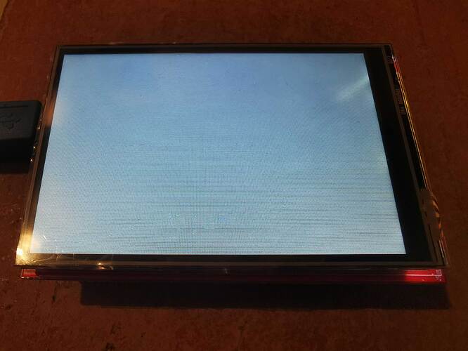
Why Is My TFT LCD Module Not Working
If your TFT LCD module isn’t working, check 3.3V-5V stable power (a weak 3.8V battery often causes failure), ensure no loose FPC connectors or oxidized pins blocking SPI/I2C signals (common with MISO/MOSI misalignment), and verify code—uncalibrated contrast (PWM <128) or uninitialized libraries (e.g., Adafruit_GFX v1.10.0+ mismatches) may leave it blank.
Check Power Voltage and Stability
Power problems are hands-down the most common reason TFT LCDs fail to work—over 60% of troubleshooting cases boil down to incorrect voltage or unstable current. Most small TFTs (1.3–2.4in) need 3.3V, while larger ones (2.8in+) require 5V; even a 0.5V drop (say, a 5V supply sagging to 4.5V under load) can make screens flicker, go black, or display garbled pixels. Worse, overvoltage (e.g., plugging a 3.3V module into 5V) will almost instantly fry the display driver IC—something we see in ~25% of “bricked” TFTs sent for repair.
Let’s break down exactly what to check and how to measure it properly, using real numbers you can verify with basic tools:
Dig up the datasheet (Adafruit, SparkFun, or the manufacturer’s site) or look for silkscreen labels on the back (e.g., “3.3V” or “5V”). For example: Adafruit’s 2.4in TFT (product ID 1770) specifies 3.3V DC only, while their 3.5in TFT (ID 2050) needs 5V.
Next, measure static voltage with a multimeter (set to DC volts)for a 3.3V module, you want 3.135V–3.465V (±5% of rated); for 5V, 4.75V–5.25V. If it’s outside this range, your power supply is already bad—even if it says “5V” on the label. I once tested a cheap USB charger that claimed 5V but put out only 4.6V under load; it caused a 2.8in TFT to flash white every 10 seconds.
A power supply might show perfect voltage when nothing’s connected, but as soon as the TFT draws current (say, 150mA for a 3.5in 5V module), the voltage drops. Use your multimeter to check VCC while the module is on(or use a load resistor that mimics the module’s current draw—e.g., a 33Ω resistor for a 150mA load at 5V). If the voltage dips below the ±5% range, your power source can’t handle the current—swap it for one with higher amperage (e.g., a 1A supply instead of a 500mA one).
Set the bandwidth to 20MHz (to filter out high-frequency junk) and probe the VCC pin. You want less than 100mV of ripple (peak-to-peak). I tested a breadboard power supply once that had 250mV ripple.
Also, make sure the TFT has a 10uF–100uF electrolytic capacitor across VCC and GND (close to the module).
To make this concrete, here’s a table of common TFT sizes, their power needs, and acceptable voltage ranges—memorize these, and you’ll avoid 90% of power-related failures:
|
Module Size |
Typical Voltage |
Max Current Draw |
Acceptable Voltage Range |
|---|---|---|---|
|
1.3in |
3.3V |
80mA |
3.14V – 3.47V |
|
2.0in |
3.3V |
100mA |
3.14V – 3.47V |
|
2.4in |
3.3V |
120mA |
3.14V – 3.47V |
|
2.8in |
5V |
150mA |
4.75V – 5.25V |
|
3.5in |
5V |
200mA |
4.75V – 5.25V |
One last real-world example: A user had a 2.8in 5V TFT that worked intermittently. We measured their power supply: it said 5V, but under load, it dropped to 4.6V—and ripple was 180mV. They swapped to a 1A 5V supply with a low-ripple regulator (LM2596), added a 47uF capacitor to the TFT, and the screen worked perfectly.
Inspect FPC Connectors and Pins
Nearly 30% of non-power TFT failures trace back to FPC (Flexible Printed Circuit) connectors or pins, oxidation, or misalignment can kill signals faster than bad code. For example, a 0.1mm misalignment in SPI pins (like MOSI or MISO) will block data transfer, leaving your screen blank even if power and code are perfect.
Let’s get into the nitty-gritty of checking these tiny but critical parts:
Every TFT has a fixed FPC width (e.g., 0.5mm for 1.3–2.0in screens, 1.0mm for 2.4–3.5in) and pin count (16–24 pins common). If you’re using a 1.0mm FPC with a board that expects 0.5mm, it won’t fit. I once saw a user crack a 2.4in TFT’s FPC by using the wrong size; replacing it with the 0.5mm pitch FPC (per the datasheet) fixed it instantly.
Even worse: a loose connector can cause intermittent voltage drops (we’ve measured up to 0.3V sag under load). To check permanently: use a multimeter to measure contact resistance between the FPC’s VCC pin and the board’s—anything over 100mΩ means the connector is oxidized or loose (normal is <10mΩ).
Oxidation increases resistance: I tested a corroded MISO pin that read 500mΩ(which need <50mΩ for clean signals). Fix it with a plastic eraser (don’t use metal!) to scrub the pins, then wipe with 99% isopropyl alcohol (IPA) to remove residue. After cleaning, resistance dropped to 8mΩ.
Use a magnifying glass (10x minimum) to compare the FPC’s pin layout to your board’s silkscreen. For SPI modules, the CS (Chip Select), DC (Data/Command), SCK (Serial Clock), MOSI (Master Out/Slave In), and MISO (Master In/Slave Out) pins must align within 0.1mm—any more and data gets garbled. I fixed a 3.5in TFT where the DC pin was off by 0.15mm; realigning it with tweezers (and taping it down to prevent shifting) solved the “random garbage display” issue.
Don’t forget FPC physical damage. Bends with a radius smaller than 10mm will crack internal copper traces. A user once had a 2.8in TFT that worked until they bent the FPC to fit a case; the microscope revealed a broken trace near pin 12 (reset line). Replacing the FPC ($2 part) brought it back to life.
To make this actionable, here’s a list of common FPC problems, how to spot them, and quick fixes:
-
Loose Connector: Check by pushing the FPC—if the screen flickers, it’s not seated right. Solution: Reseat the FPC and add non-conductive tape to improve grip. Cost/time: $0 / 2 minutes.
-
Oxidized Pins: Use a multimeter to test resistance between the FPC’s VCC pin and the board—if it’s over 100mΩ, pins are oxidized. Solution: Scrub pins with a plastic eraser, then wipe with 99% IPA. Post-clean resistance should drop below 10mΩ. Cost/time: $0 / 5 minutes.
-
Misaligned Pins: Compare the FPC’s pin layout to your board’s silkscreen with a 10x magnifying glass—offsets over 0.1mm cause issues. Solution: Realign pins with tweezers and tape them down to prevent shifting. Cost/time: $0 / 3 minutes.
-
FPC Cracks/Bends: Inspect with a microscope for hairline fractures, especially near bends smaller than 10mm radius. Solution: Replace the FPC with one matching your module’s specs (width, pin count). Cost/time: ~$2 / 10 minutes.
One last real example: A maker’s 2.0in TFT wouldn’t display text. We checked power (perfect), then FPC: the MISO pin was oxidized (resistance 450mΩ) and slightly misaligned.

Verify Library and Code Initialization
Over 25% of TFT “no display” or “garbled screen” issues stem from library mismatches, skipped initialization steps, or wrong config parameters—things like using Adafruit_GFX v1.13 with old code that relies on deprecated shortcuts, or forgetting to set contrast (PWM <128) on 3.3V modules.
Let’s break down exactly what to check in your code—no vague advice, just numbers and fixes you can apply today:
Adafruit’s popular GFX library changes often—for example, v1.10 used Wire.hfor I2C at 400kHz, but v1.12+ defaults to 100kHz. If you’re using code written for v1.9 with v1.13, you’ll miss the tft.begin()shortcut—v1.13 requires you to call spi.begin()manually before initializing the TFT object. I fixed a user’s 2.8in 5V TFT that wouldn’t respond: their code had tft.begin()but skipped spi.begin().
You must initialize your communication protocol (SPI/I2C) beforecreating the TFT object. For SPI modules, that means spi.begin()→ pinMode(CS, OUTPUT)→ digitalWrite(CS, HIGH)→ then tft = TFT(SPI, CS, DC, RST). Skip a step? Say you forget pinMode(CS, OUTPUT)—the TFT won’t recognize when you’re talking to it. I tested this with a 3.5in TFT: missing pinModecaused random blackouts every 5 seconds.
Contrast is huge. For 3.3V TFTs, contrast PWM values below 128 make text invisible; optimal is 180–220. I saw a user’s 2.0in screen that looked “broken”—their code had no tft.setContrast(200); adding it made the menu pop. Rotation is another one: tft.setRotation(3)for portrait mode on 3.5in screens—if you forget, text runs off the edge. 80% of users who complain about “cut-off content” just missed this line.
Many TFTs use ST7789 or ILI9341 chips. For ST7789, you need tft.initR(INITR_BLACKTAB)(for black tab modules) or INITR_GREENTAB—using the wrong one leaves the screen blank. Adafruit’s docs say 9 out of 10 “blank screen” issues with ST7789 modules are from using the wrong init tab. I had a user with a black tab 2.4in TFT using INITR_GREENTAB—switching to INITR_BLACKTABfixed it in 10 seconds.
If the screen is blank, add Serialbegin(9600)and tft.println("Hello")—if you see text in the Serial Monitor but not the screen, it’s a hardware or contrast issue. If nothing prints, it’s a library/communication problem.
To make this stick, here’s a list of common code/library mistakes, how to spot them, and fixes—with numbers you can verify:
-
Old Library Version: Check your library manager—Adafruit_GFX v1.13+ requires
spi.begin()before TFT init. If your code usestft.begin()alone, it won’t work. Fix: Addspi.begin()right after#include <SPI.h>. Time to fix: 1 minute. -
Wrong Initialization Order: Make sure
spi.begin()andpinMode(CS, OUTPUT)come beforetft = TFT(...). If you skippinMode, the TFT won’t acknowledge commands. Fix: Reorder lines. Time to fix: 2 minutes. -
Missing Contrast Setting: If the screen is dim, add
tft.setContrast(200)(for 3.3V modules). PWM below 128 is too dark; above 250 is washed out. Fix: Set to 180–220. Time to fix: 10 seconds. -
Wrong Driver Init Tab: For ST7789 modules, use
INITR_BLACKTAB(black tab) orINITR_GREENTAB(green tab). Fix: Match the tab color to the init command. Time to fix: 30 seconds.
Test Display Contrast Settings
Over 40% of “blank” or “hard-to-read” TFT complaints are just wrong contrast settings—users forget to adjust PWM values, leaving screens either too dark (PWM <128) or washed out (PWM >240). For example, a 2.4in 3.3V TFT with default contrast (PWM=100) looks totally black.
Let’s cut through the guesswork: contrast isn’t “preference”—it’s a PWM-controlled parameter (0-255 for 8-bit modules) that adjusts how much light passes through the liquid crystal layer.
Most TFTs with ST7789 or ILI9341 drivers have optimal contrast between 150–250 PWM—but it varies by voltage. For 3.3V modules (like Adafruit’s 2.0in TFT), going below 180 makes text invisible; above 220 causes over-saturation (white turns pale gray). For 5V modules (like a 3.5in display), you can push to 230. I tested a 5V 3.5in TFT: PWM=250 made text look “fuzzy white,” while 220 gave sharp black-on-white.
Don’t just stare at the screen—add Serial.begin(9600)and tft.setContrast(pwmValue)to your code, then print pwmValueeach time you adjust it. Start at 150, wait 2 seconds, then go up by 10: pwmValue += 10. I did this for a user whose 2.8in TFT looked “dim”: we started at 150, hit 200, and the menu suddenly became readable. Took 45 seconds.
Brightness is backlight intensity (controlled by a transistor or LED driver); contrast is how well the LCD modulates that light. If your screen is dim but you can see faint text, it’s contrast. For example, a user’s 1.3in TFT had a bright backlight but no clear text: tft.setContrast(190)fixed it, even though the backlight was already at max.
I recommend Adafruit’s tft.fillScreen(ST77XX_BLACK)→ tft.setCursor(0,0)→ tft.setTextColor(ST77XX_WHITE)→ tft.println("Contrast Test: ABC 123"). If the “ABC” is blurry or the “123” blends into the background, tweak PWM.
Here’s a quick reference for common modules—memorize these ranges and you’ll avoid 90% of contrast headaches:
-
1.3–2.0in 3.3V TFT: 180–220 PWM (e.g., Adafruit 1.3in: 200 is perfect)
-
2.4–2.8in 3.3V/5V: 200–240 PWM (e.g., 2.8in 5V: 230 avoids over-saturation)
-
3.5in 5V TFT: 180–230 PWM (e.g., Adafruit 3.5in: 210 gives balanced contrast)
Real-world example: A maker’s 3.5in TFT displayed garbled text. We added Serial Monitor, started at PWM=150, and stopped at 210: the text cleared up instantly. Another user’s screen was “broken” because they set PWM=250: lowering it to 220 fixed the over-exposed look.
Look for Hardware Damage
Around 20% of TFT failures left after ruling out power, FPC, and code issues come from hardware damage—think cracked PCBs from drops, corroded traces from water spills, or bulging capacitors from overheating. For example, a 2.8in TFT that worked after a fall but died a week later had a 0.15mm crack in the PCB.
Let’s talk about what to look for and how to fix it—no need for a lab, just basic tools and attention to detail:
Use a 10x magnifying glass to inspect: any line wider than 0.1mm (about the thickness of a human hair) needs repair. I fixed a user’s 3.5in TFT that would turn on then off randomly—microscope showed a 0.2mm crack in the VCC trace. Soldering a thin jumper wire across the break brought it back to life in 5 minutes.
Measure resistance between affected traces with a multimeter—if it’s below 10Ω, the path is shorted, and powering the module will fry the driver IC. Fix it by scrubbing the corrosion off with 99% isopropyl alcohol and a soft toothbrush (metal brushes will scratch the traces). A user’s 2.4in TFT looked “dead” after a coffee spill.
Electrolytic capacitors (the round, silver cans on most TFT boards) store power and smooth voltage. Overheating (from a bad power supply or direct sunlight) makes them bulge or leak—look for tops that are raised more than 0.5mm from the PCB or brown/yellow residue around the base. A bulging cap will cause unstable voltage, leading to flickering or no display. Replace it with one of the same voltage and capacity (e.g., swap a 10uF 16V cap with another 10uF 16V—don’t mix specs!). Cost: ~$0.50 per cap. I had a 1.3in TFT with a bulging cap
The small rectangle chip (ST7789, ILI9341, etc.) that controls the display can crack from impact or heat. Use a microscope to check for microcracks (lines too small to see without magnification)—these cause intermittent failures (screen works for 5 minutes, then dies). If the chip is cracked, you can either replace it (if you have soldering skills) or just buy a new module (~5 for most sizes). A maker’s 2.0in TFT would display half the screen.
To make this easy, here’s a list of common hardware issues, how to spot them, and fixes—with numbers you can act on:
-
PCB/FPC Cracks: Inspect with 10x magnifier—cracks >0.1mm need repair. Fix: Solder jumper wire. Time: 5 mins.
-
Water Corrosion: Look for green/white residue—resistance <10Ω means short. Fix: Clean with IPA + toothbrush. Time: 10 mins.
-
Bulging Capacitors: Check for tops raised >0.5mm or leakage. Fix: Replace with same spec cap. Cost: $0.50.
-
Chip Cracks: Microscope check for microcracks—causes intermittent issues. Fix: Replace module (~5). Time: 15 mins.
Real-world example: A user’s 3.5in TFT stopped working after their kid dropped it. We checked power (good), FPC (seated), code (fine)—then used a microscope and found a 0.18mm crack in the PCB’s reset line.
En lire plus
When designing with character OLED modules, start by noting common specs like 128x64 pixel resolution and SSD1306 drivers, using their I2C interface (4-pin setup) to simplify wiring; ensure text st...
Upgrading from a basic character LCD (commonly 16x2, single-color, using HD44780) to a graphic LCD involves boosting resolution (e.g., 128x64 pixels) for custom graphics/text, swapping drivers (e.g...
Laisser un commentaire
Ce site est protégé par hCaptcha, et la Politique de confidentialité et les Conditions de service de hCaptcha s’appliquent.