


0.49" Micro OLEDoS Display 1920x1080 90Hz 3000nits - MIPI
- 💹 Enjoy a 20% discount for orders over 500
- 📉 A 15% discount is available for orders ranging from 200 to 499
- 🎁 A 10% discount is available for orders ranging from 50 to 199
- 🎁 A 5% discount is available when ordering 10-49
Interested in customizing this product? Get in touch with us.
Order samples, immediate delivery.
Factory bulk lead time: 3 weeks.
0.49" Micro OLEDoS Display 1920x1080 90Hz 3000nits - MIPI
- 💹 Enjoy a 20% discount for orders over 500
- 📉 A 15% discount is available for orders ranging from 200 to 499
- 🎁 A 10% discount is available for orders ranging from 50 to 199
- 🎁 A 5% discount is available when ordering 10-49
Resources & Downloads
DM-OLED049-1003 · Micro OLEDoS Display Module
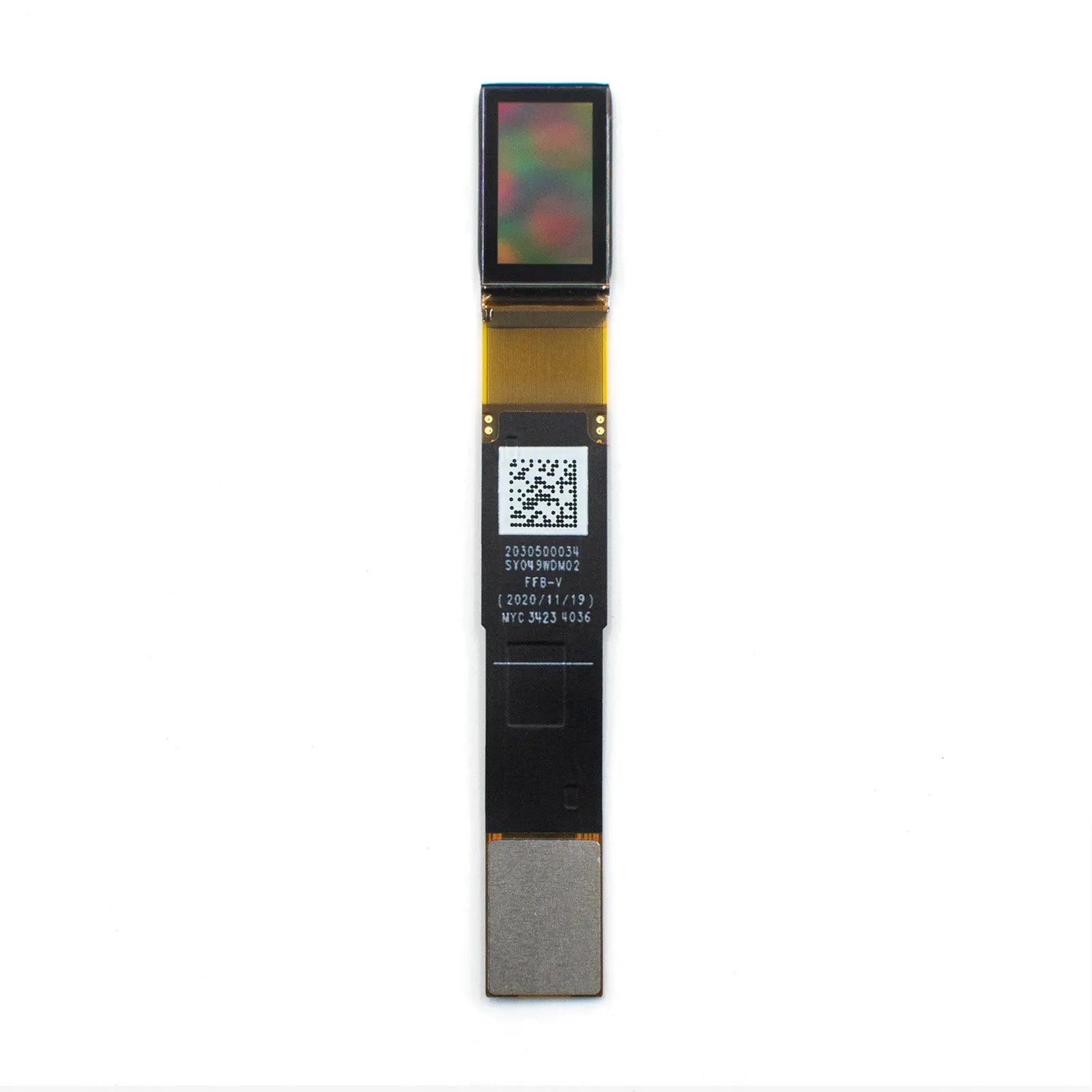
0.49" Micro OLEDoS Display 1920×1080 90Hz 3000nits - MIPI
This 0.49-inch Micro OLEDoS display is based on a single-crystal silicon backplane and integrates panel driving and logic driving functions in a compact module. It provides 1920(H) × 1080(V) resolution, 5.616μm pixel size, a 10.783mm × 6.065mm active area, and high-brightness full-color output for near-eye and compact optical display systems.

Datasheet-Based Technical Specifications
| Parameter | Specification | Engineering Note |
|---|---|---|
| Display Type | Active matrix color Micro-OLED / OLEDoS | OLED pixels on a silicon backplane for compact near-eye optical systems. |
| Resolution | 1920(H) × 1080(V) | Full HD image output; the datasheet also describes an SPR dot arrangement. |
| Pixel Size | 5.616μm × 5.616μm | Small pixel pitch supports high pixel density after optical magnification. |
| Active Area | 10.783mm × 6.065mm / 0.49" diagonal | Defines optical magnification, field of view, and mechanical alignment requirements. |
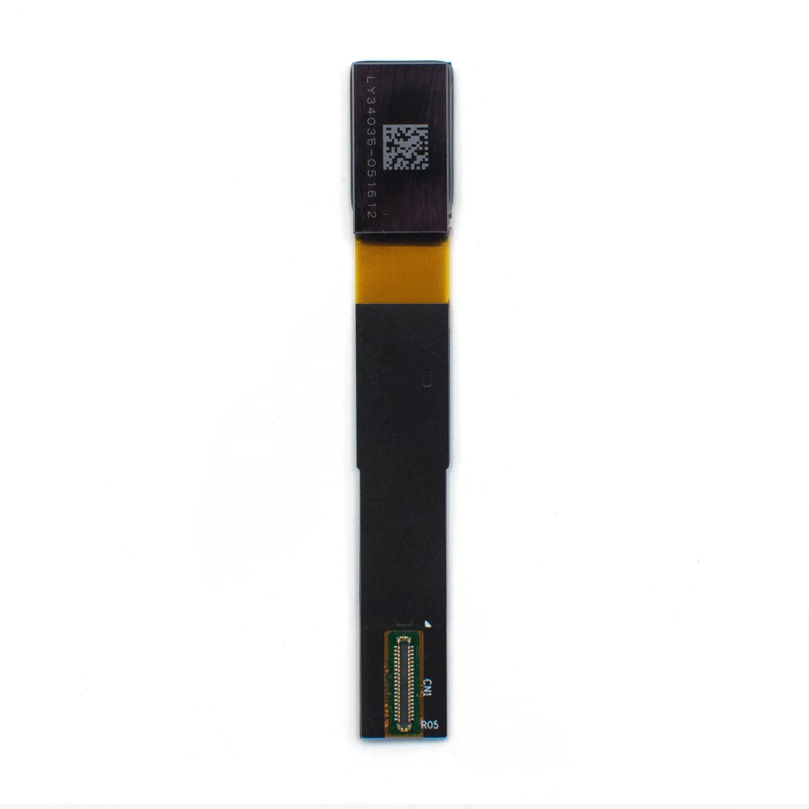
| Module Outline / Bezel | 15.68mm × 9.09mm × 1.5mm | Use the mechanical drawing and FPC layout before lens or housing tooling. |
| Luminance | 3000 cd/m² typical | Panel-side value; eye-side brightness depends on lens, prism, waveguide, coating, and combiner losses. |
| Contrast Ratio | 50,000:1 | OLED contrast supports deep-black image areas without LCD backlight leakage. |
| Color Gamut | 95% DCI-P3 | Final color accuracy depends on calibration, optical stack, driving settings, and viewing environment. |
| Color / Gray Levels | 8-bit or 10-bit supported; 256 or 1024 gray levels | 16.7M color output applies to 8-bit-per-channel operation. |
| Frame Rate | Max. 90Hz | Host MIPI timing, compression mode, thermal margin, and power design should be verified together. |
| Interface | MIPI DSI + I2C | MIPI is used for video data; I2C is used for register and control configuration. |
| MIPI Physical Layer | MIPI D-PHY v1.2, one port, 4 lanes, 1.0Gbps/lane | Check host lane count, DSI video mode support, connector routing, and signal integrity. |
| Compression / Scaling | VESA-DSC v1.1 decoder; 3× and 3.75× compression; 1.33× / 1.5× / 2× scaling support | Validate compression settings and image quality on the selected controller platform. |
| Operating Voltage | AVDD: 5.3V–5.5V; AVEE: -4V to -5.5V; VDDI: 1.65V–1.95V | Power rail sequencing, ripple, and shutdown behavior should follow the official datasheet. |
| Power Consumption | 480mW under the datasheet condition: 90Hz, 1800nits, VESA on, full white, 1920×1080 input, rolling mode | Actual power varies with brightness, image content, frame rate, emission mode, and thermal environment. |
| Operating Temperature | -20°C to +70°C | Thermal performance should be checked inside the final enclosure or optical module. |
| Storage Temperature | -40°C to +80°C | Relevant for logistics, warehousing, and non-operating device exposure. |
| Weight | Approximately 1g | Low display weight helps reduce mass in wearable and compact optical engines. |
Interface, Driving & Thermal Review
MIPI DSI + I2C Control
The module uses MIPI DSI video input and I2C register control. Before PCB layout, confirm DSI video timing, lane configuration, I2C initialization, reset timing, and host-controller compatibility.
VESA-DSC & Scaling
Integrated VESA-DSC decoding and scaling functions can reduce transmission bandwidth or rendering load. Compression mode, scaling ratio, frame timing, and image quality should be validated on the final SoC.
Power & Thermal Margin
Design stable AVDD, AVEE, and VDDI rails with controlled sequencing. Thermal design should be checked under high-brightness UI, full-white content, enclosed shells, and continuous operating scenarios.
Application Fit by Engineering Requirement
AR Optical Engines
3000 cd/m² panel luminance provides brightness margin for optical paths with lens, prism, waveguide, or combiner losses. Final eye-side brightness must be calculated and tested in the target optical architecture.
Viewfinders & Head-Mounted Displays
Full HD resolution, high pixel density, and up to 90Hz operation support compact EVF and HMD display modules. Motion performance should be verified with the final driving board and optical magnification.
Medical Visualization Evaluation
High contrast and 95% DCI-P3 color gamut can support visualization-device evaluation. This display is a component; diagnostic use, clinical performance, safety certification, and regulatory approval depend on the finished device.
Industrial Optical Equipment
The compact outline, MIPI interface, high luminance, and -20°C to +70°C operating range make the module relevant for inspection tools, microscopes, measurement devices, and portable optical terminals.
Prototype Development
For EVT or prototype builds, confirm sample availability, datasheet version, connector direction, FPC bend radius, initialization sequence, display board support, and optical acceptance criteria.
Mass Production Review
Before production, define incoming inspection standards, display aging criteria, brightness uniformity limits, image retention review, packing method, lead time, and long-term supply planning.
Engineering Checklist Before PCB or Optical Tooling
Optical Path Budget
Calculate display-side luminance, expected optical transmission, eye-side brightness, contrast under ambient light, and thermal impact at target brightness.
Host Controller Matching
Verify MIPI DSI video mode, four-lane D-PHY routing, 1.0Gbps/lane operation, DSC configuration, I2C control, and initialization timing.
Power Rail Sequencing
Check AVDD, AVEE, and VDDI ramp timing, ripple, transient response, shutdown behavior, ground return path, and ESD precautions.
Reliability & Image Quality
Review brightness uniformity, color shift, image retention risk, long-run thermal behavior, vibration, humidity exposure, and final product burn-in criteria.
Download Datasheet & Confirm Integration Details
Use the official datasheet to confirm mechanical drawings, recommended operating conditions, interface timing, power rail requirements, register settings, reliability limits, and handling precautions before PCB layout or optical engine tooling.
Download Official Datasheet