









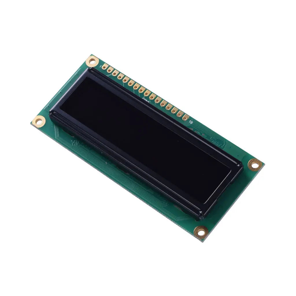
16x2 OLED Character Display - MCU, SPI, I2C
- 💹 Enjoy a 20% discount for orders over 500
- 📉 A 15% discount is available for orders ranging from 200 to 499
- 🎁 A 10% discount is available for orders ranging from 50 to 199
- 🎁 A 5% discount is available when ordering 10-49
Interested in customizing this product? Get in touch with us.
Order samples, immediate delivery.
Factory bulk lead time: 3 weeks.
16x2 OLED Character Display - MCU, SPI, I2C
- 💹 Enjoy a 20% discount for orders over 500
- 📉 A 15% discount is available for orders ranging from 200 to 499
- 🎁 A 10% discount is available for orders ranging from 50 to 199
- 🎁 A 5% discount is available when ordering 10-49
Resources & Downloads
16×2 Character OLED Display with WS0010, Parallel and 3-Line Serial Interfaces
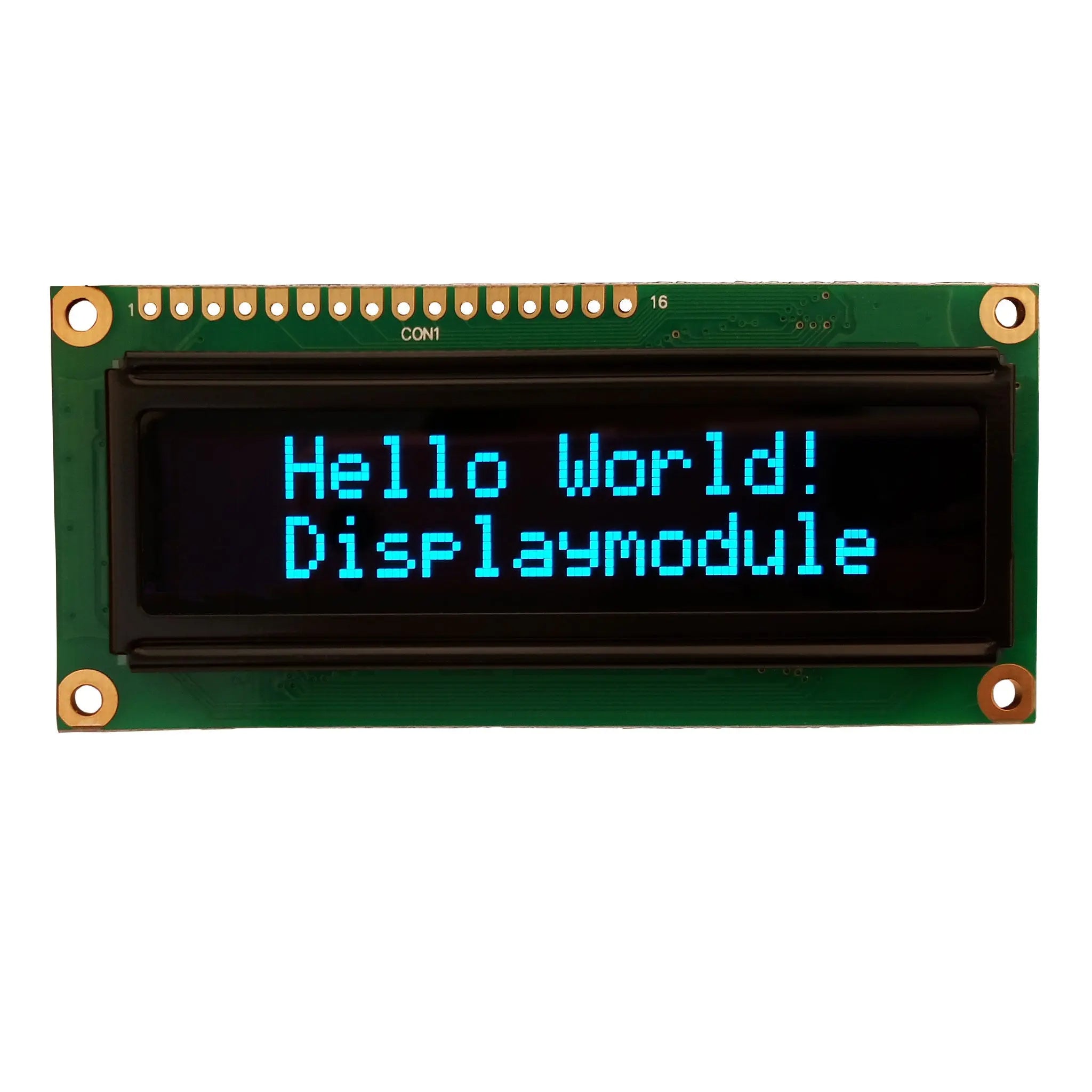
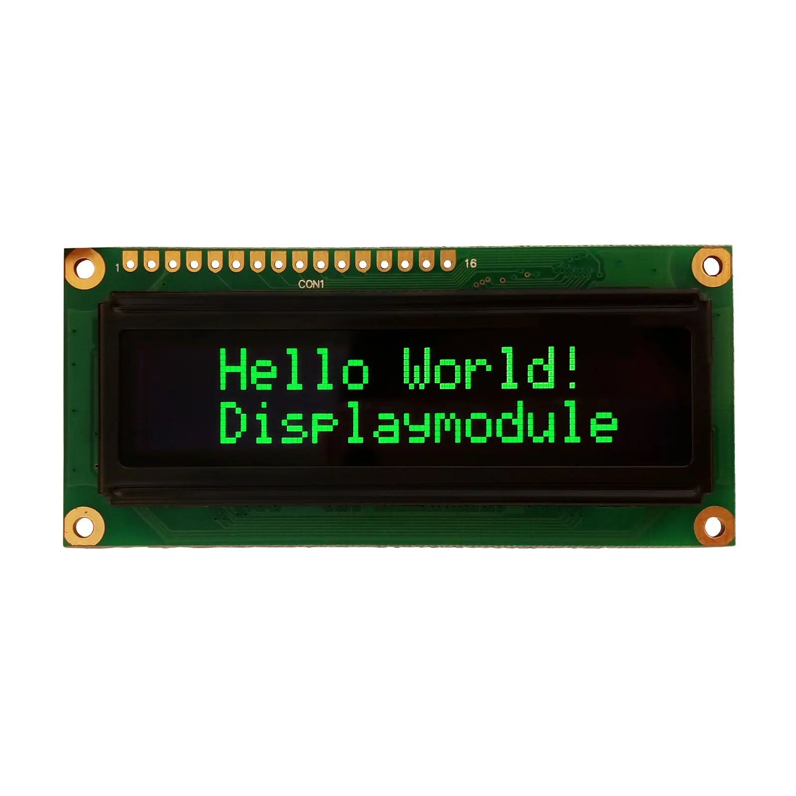
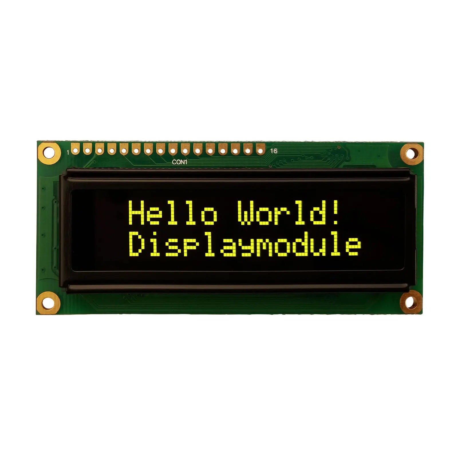
This passive-matrix character OLED module displays 16 characters on each of two lines and is offered in blue, green and yellow emitting-color variants. The supplied engineering documentation specifies an integrated WS0010 controller, a 1/16 duty drive configuration, and selectable parallel or serial MPU communication.
The module uses self-emissive OLED technology and does not require a separate backlight. Its documented electrical, optical, mechanical, pin-assignment, command and reliability data support component selection, PCB planning and sample evaluation.

Verified Technical Specifications
The following specifications support electrical design, enclosure planning, interface selection and sample evaluation.
| Parameter | Verified Specification |
|---|---|
| Display Type | Passive-matrix character OLED display |
| Display Format | 16 characters × 2 lines |
| Available Emitting Colors | Blue, green and yellow, selected by product variant |
| Controller IC | WS0010 OLED driver/controller |
| Display Duty | 1/16 duty |
| Character Font | 5 × 8 dot character format for the documented two-line configuration |
| Interface Modes | 6800 parallel interface by default; jumper-selectable 8080 parallel or 3-line serial interface |
| Logic Supply Voltage | 3.0 V minimum, 3.3 V typical, 3.6 V maximum |
| 50% Operation Current | 52 mA minimum, 57 mA typical, 65 mA maximum under the datasheet test condition |
| Module Outline | 80.0 ± 0.5 mm × 36.0 ± 0.5 mm × 10.0 mm maximum |
| Viewing Area | 66.0 mm × 16.0 mm |
| Active Area | 56.95 mm × 11.85 mm |
| Weight | 22.8 g |
| Operating Temperature | -40°C to +80°C, absolute maximum range |
| Storage Temperature | -40°C to +80°C, absolute maximum range |
| Touch Function | No touch panel or touch controller is identified in the supplied product datasheet |
Optical Performance and OLED Lifetime Data
The datasheet defines viewing angle, response time, contrast, checkerboard brightness and estimated operating lifetime. Test conditions should be considered when comparing this module with other character-display technologies.
Estimated operating lifetime: 40,000 hours minimum and 50,000 hours typical. The datasheet defines lifetime as the time for luminance to decay below 50% of its initial value and notes that screen-saving operation can extend OLED life.
Interface Selection and Pin Assignment
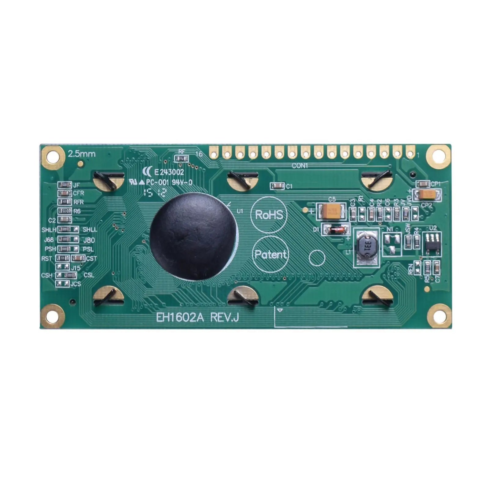
The module is documented with a 16-position through-hole connection row. Interface selection is controlled by hardware jumper settings, so the required mode should be confirmed before PCB layout and assembly.
Three Documented Interface Modes
The product datasheet identifies one default mode and two jumper-selectable alternatives.
Parallel Interface Pins
3-Line Serial Interface Pins
I2C clarification: The supplied product datasheet documents 6800 parallel, 8080 parallel and 3-line serial operation. It does not identify a native I2C interface or an I2C device address.
Controller Functions for Firmware Planning
The WS0010 specification documents the functions required to write characters, control the cursor, create custom patterns and select supported character tables.
Display and Character RAM
128 × 8-bit display RAM and 64 × 8-bit character-generator RAM are documented.
Custom Character Patterns
CGRAM supports up to eight custom 5 × 8 character fonts or four custom 5 × 10 fonts.
Four Selectable Character Tables
English/Japanese, Western European I, English/Russian and Western European II tables are listed.
Display Control Instructions
Clear, home, display on/off, cursor on/off, blink, cursor shift, display shift and address commands are documented.
Busy-Flag and Address Reading
The controller provides a busy flag and address counter for firmware-controlled command sequencing.
Mechanical Integration Details
Use the mechanical drawing as the controlling reference for enclosure cutouts, PCB header placement, mounting-hole clearance and display-window alignment.
Layout Review
Review the outline, viewing area, active area, mounting pattern and header position together. The drawing states a general unspecified dimensional tolerance of ±0.3 mm.
Documented Reliability Test Conditions
These test conditions help engineering and purchasing teams review environmental tolerance before sample qualification and product design. They are qualification references rather than a substitute for system-level validation.
The datasheet also lists atmospheric-pressure and static-electricity test conditions. Final suitability should be confirmed through customer-specific assembly and system testing.
Engineering Review Before Ordering
Confirm the points below before committing the PCB, enclosure or volume purchase. This reduces the risk of interface, color, revision or mechanical mismatches.
Confirm the Exact Part Number
Match the selected blue, green or yellow variant to its SKU and revision-specific product documentation.
Select the Interface Before Assembly
Determine whether the design requires default 6800 parallel, 8080 parallel or 3-line serial operation, then confirm the corresponding jumper configuration.
Check Logic Levels and Current Budget
Design for the documented 3.0-3.6 V VDD range and review the 50% operation-current values when planning the supply rail.
Review Initialization and Busy Timing
Follow the initialization sequence and command timing defined in the product and WS0010 documents. Check the busy flag when the selected interface permits reading.
Validate the Mechanical Stack-Up
Confirm the display window, mounting-hole locations, connector clearance and maximum 10.0 mm module depth in the completed enclosure.
Confirm with DisplayModule
Project-specific commercial and configuration details should be confirmed before ordering.
Common Integration Questions
Answers are limited to information supported by the supplied product and controller documentation.
Does this module require a backlight?
No. It is a self-emissive OLED module, so a separate LCD backlight is not required.
Does the supplied datasheet confirm native I2C?
No. The product datasheet lists 6800 parallel, 8080 parallel and 3-line serial modes. It does not list an I2C address or a native I2C operating mode.
Can the parallel bus operate in 4-bit mode?
Yes. The WS0010 documentation describes both 4-bit and 8-bit MPU data-transfer operation. In 4-bit mode, DB4 through DB7 are used and each complete transfer requires two 4-bit operations.
What should be used as the nominal supply voltage?
The datasheet specifies 3.3 V as the typical VDD value, with a documented range from 3.0 V to 3.6 V.
Is a touch panel included?
No touch panel, touch controller or touch-related pin assignment is identified in the supplied datasheet.
Which emitting colors are available?
The storefront provides blue, green and yellow variants. Select the required color and confirm the corresponding SKU and revision-specific documentation before production approval.
What should be checked before production PCB release?
Check the exact part number, VDD range, interface jumper mode, 16-pin assignment, initialization sequence, busy timing, mounting-hole pattern, viewing area and maximum module depth.
Download Engineering Files
Access the display datasheet, WS0010 controller documentation, and the Arduino library with example code for mechanical, electrical, firmware, and integration reference.