









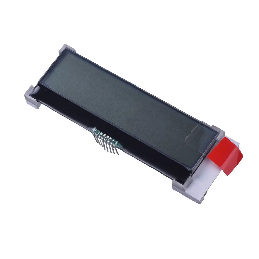
20x2 Character COG LCD FSTN Transflective - I2C
- 💹 Enjoy a 20% discount for orders over 500
- 📉 A 15% discount is available for orders ranging from 200 to 499
- 🎁 A 10% discount is available for orders ranging from 50 to 199
- 🎁 A 5% discount is available when ordering 10-49
Interested in customizing this product? Get in touch with us.
Order samples, immediate delivery.
Factory bulk lead time: 3 weeks.
20x2 Character COG LCD FSTN Transflective - I2C
- 💹 Enjoy a 20% discount for orders over 500
- 📉 A 15% discount is available for orders ranging from 200 to 499
- 🎁 A 10% discount is available for orders ranging from 50 to 199
- 🎁 A 5% discount is available when ordering 10-49
Resources & Downloads
20x2 Character COG LCD Module with FSTN Positive Transflective Display and I2C Interface
DM-COG2002-713 is a 20 characters × 2 lines COG character LCD module for compact text-based embedded interfaces. It uses FSTN positive transflective LCD technology, ST7036I controller IC, I2C MPU interface, and white LED backlight.
The module is specified with a 74.2 × 25.2 × 6.3 mm maximum outline, 6:00 view direction, 1/16 duty, 1/5 bias, and 3.3 V typical logic supply.

Verified Technical Specifications
The specifications below are limited to values found in the supplied product page, module datasheet, and mechanical drawing.
| Parameter | Specification |
|---|---|
| Product Model | DM-COG2002-713 |
| Product Type | COG character LCD module |
| Display Format | 20 characters × 2 lines |
| LCD Type | FSTN Positive |
| Display Mode | Transflective |
| Controller IC | ST7036I |
| Interface | I2C MPU Interface |
| Power Supply | 3.3 V typical; VDD range 3.0 to 5.0 V in the electrical characteristics table |
| View Direction | 6:00 |
| Duty / Bias | 1/16 duty, 1/5 bias |
| Backlight | White LED |
| Module Size | 74.2 × 25.2 × 6.3 mm max |
| Viewing Area | 61.0 × 15.1 mm |
| Active Area | 58.5 × 9.84 mm |
| Weight | 15.1 g |
| Operating Temperature | -20°C to +70°C |
| Storage Temperature | -30°C to +80°C |
| Touch Panel | No touch panel is specified in the supplied product page or module datasheet. |
Electrical and Optical Details
These values help engineers review the logic supply, input thresholds, LED backlight drive, view angle, and bus timing before PCB design or sample testing.
Design review values
The module datasheet lists electrical characteristics for VDD, input/output voltage levels, digital operation current, white LED voltage/current, operating temperature, and storage temperature. The controller datasheet should be reviewed for ST7036 command behavior and register-level details.
3.0 to 5.0 V range, 3.3 V typical.
Digital operation current is listed with 0.2 mA max.
White LED forward voltage is listed as 3.4 to 3.6 V.
White LED forward current is listed as 32 to 40 mA.
Top 30°, bottom 60°, right 45°, left 45°.
SCL clock frequency is listed from DC to 300 kHz.
Pin Description and I2C Interface Review
The supplied module datasheet lists eight pins. SDA and SCL must be connected to the I2C bus with pull-up resistors to the I2C bus power rail.
SDA: The datasheet lists SDA as DB7 input data in I2C interface mode.
SCL: The datasheet lists SCL as DB6 clock input in I2C interface mode.
RST: Pin 8 is listed as reset. Include reset routing in the host PCB and firmware bring-up plan.
Mechanical Data from the Drawing
The drawing should be used for front-window design, PCB clearance, pin pitch review, housing fit, and display opening alignment. The page uses one supplied image only.
Reliability Conditions for Product Evaluation
The following test conditions are listed in the module datasheet and can help customers review environmental suitability before sample evaluation and product design.
Storage
High temperature storage: 80°C for 200 hours. Low temperature storage: -30°C for 200 hours.
Operation
High temperature operation: 70°C for 200 hours. Low temperature operation: -20°C for 200 hours.
Humidity and Shock
High temperature and humidity operation: 60°C, 90% RH for 96 hours. Thermal shock: -20°C / 70°C for 10 cycles.
Vibration and ESD
Vibration testing is listed at 10 to 55 Hz. Static electricity test values include VS = 800 V, RS = 1.5 kΩ, and CS = 100 pF.
Application Fit
This module is designed for character-based information display rather than a graphic color interface. It is suitable for projects that require simple text output and compact COG LCD integration.
Control Panels
For menu text, operating status, mode indicators, and short parameter values.
Portable Instruments
For handheld meters, compact test equipment, and low-information-density interfaces.
Embedded Devices
For device front panels where I2C character display integration is preferred.
Engineering Notes Before Ordering
Items to confirm during design-in
Review these points before sample purchase, PCB layout, and firmware bring-up. Confirm any customization requirement with DisplayModule before ordering.
Power and logic: The product page highlights 3.3 V operation, while the datasheet lists VDD from 3.0 to 5.0 V. Confirm the selected bus voltage and pull-up resistor design.
Firmware: The module datasheet includes I2C initialization examples for 3 V and 5 V operation. Review the ST7036 command details before final firmware release.
Backlight: Check white LED voltage and current values before selecting a resistor, LED driver, or power rail.
Customization: For connector changes, labeling, packaging, sample availability, bulk lead time, or lifecycle review, confirm with DisplayModule before ordering.
FAQ for Sample Evaluation
Is this a graphic LCD module?
No. This product is specified as a 20 characters × 2 lines character LCD module. It is intended for text-based display content.
What controller IC is used?
The module datasheet lists ST7036I as the controller IC. The supplied ST7036 controller documentation should be reviewed for command and function details.
Is a touch panel included?
No touch panel is specified in the supplied product page or module datasheet. Confirm with DisplayModule if a cover lens, overlay, or customized front structure is required.
Can this module be used in a 5 V design?
The datasheet lists VDD from 3.0 to 5.0 V and includes 5 V initialization information. The final bus voltage, pull-up resistor design, and host logic levels should be reviewed before production use.
What should be checked before PCB layout?
Check the 8-pin assignment, 1.27 mm pin pitch reference, VDD and VSS routing, SDA and SCL pull-up design, RST connection, white LED driving conditions, and mechanical clearance.
How many product images are used on this page?
This HTML uses one supplied image only: the mechanical drawing for DM-COG2002-713.
Download Official Engineering Files
Use the module datasheet to confirm dimensions, pin assignment, electrical characteristics, timing values, initialization examples, reliability conditions, and mechanical drawing. Use the ST7036 controller datasheet to review controller-level commands and functions.