

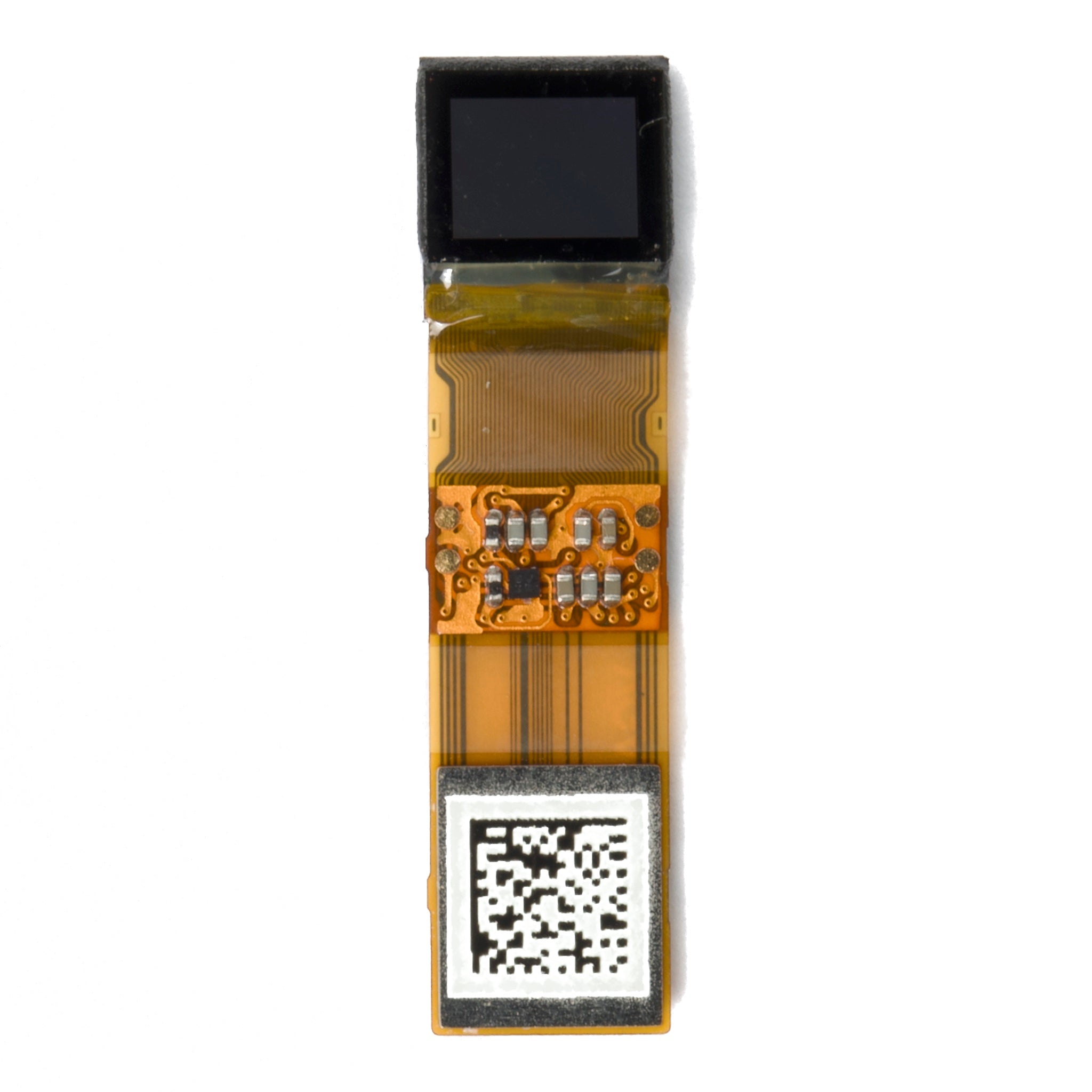
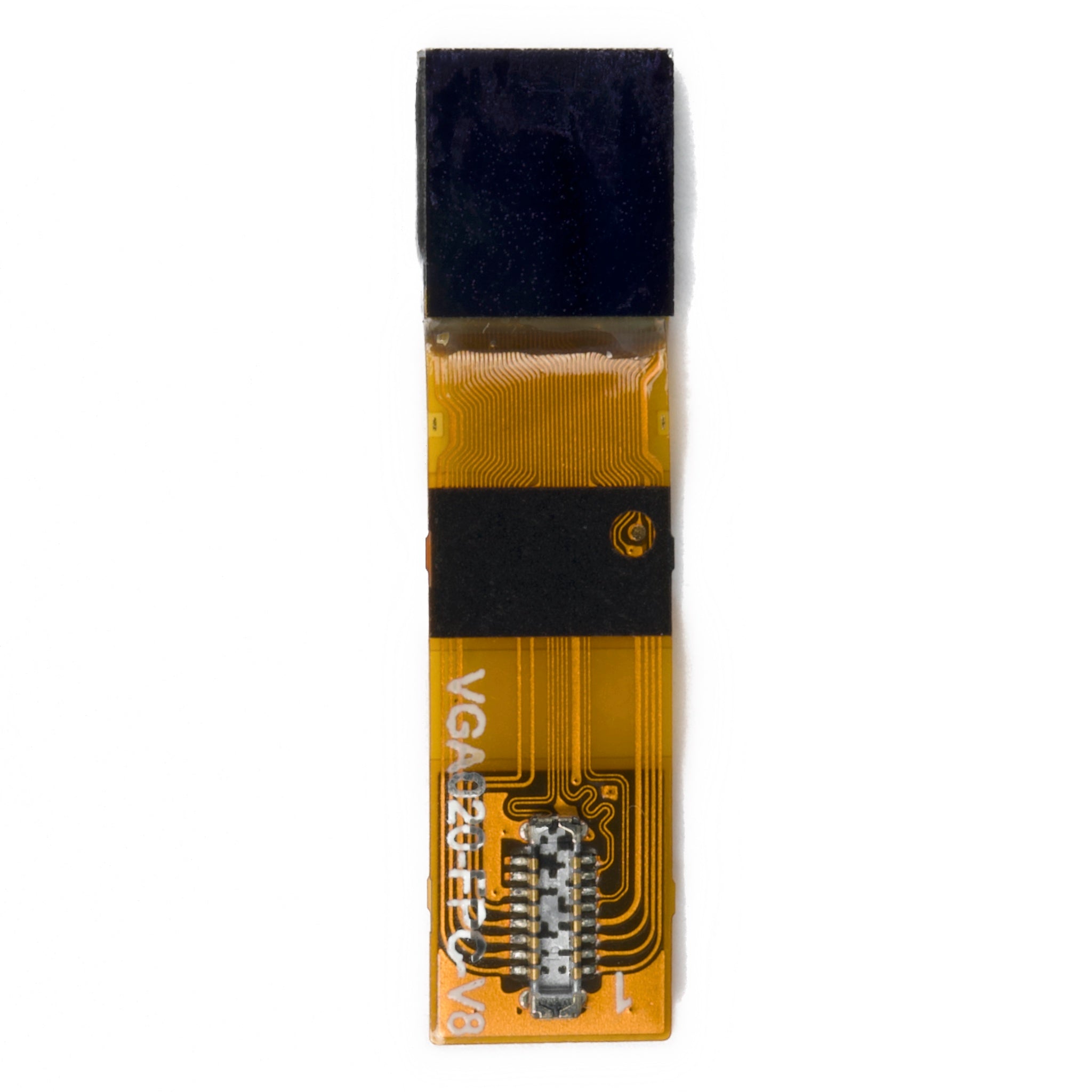
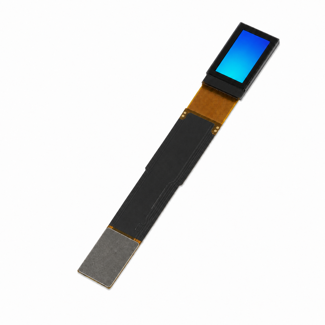
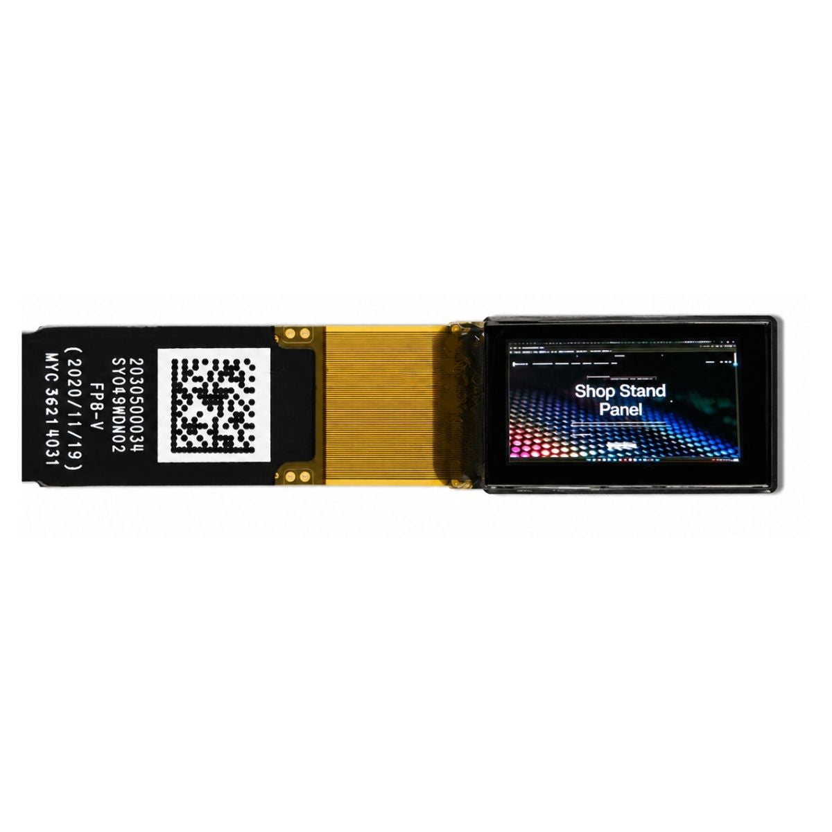
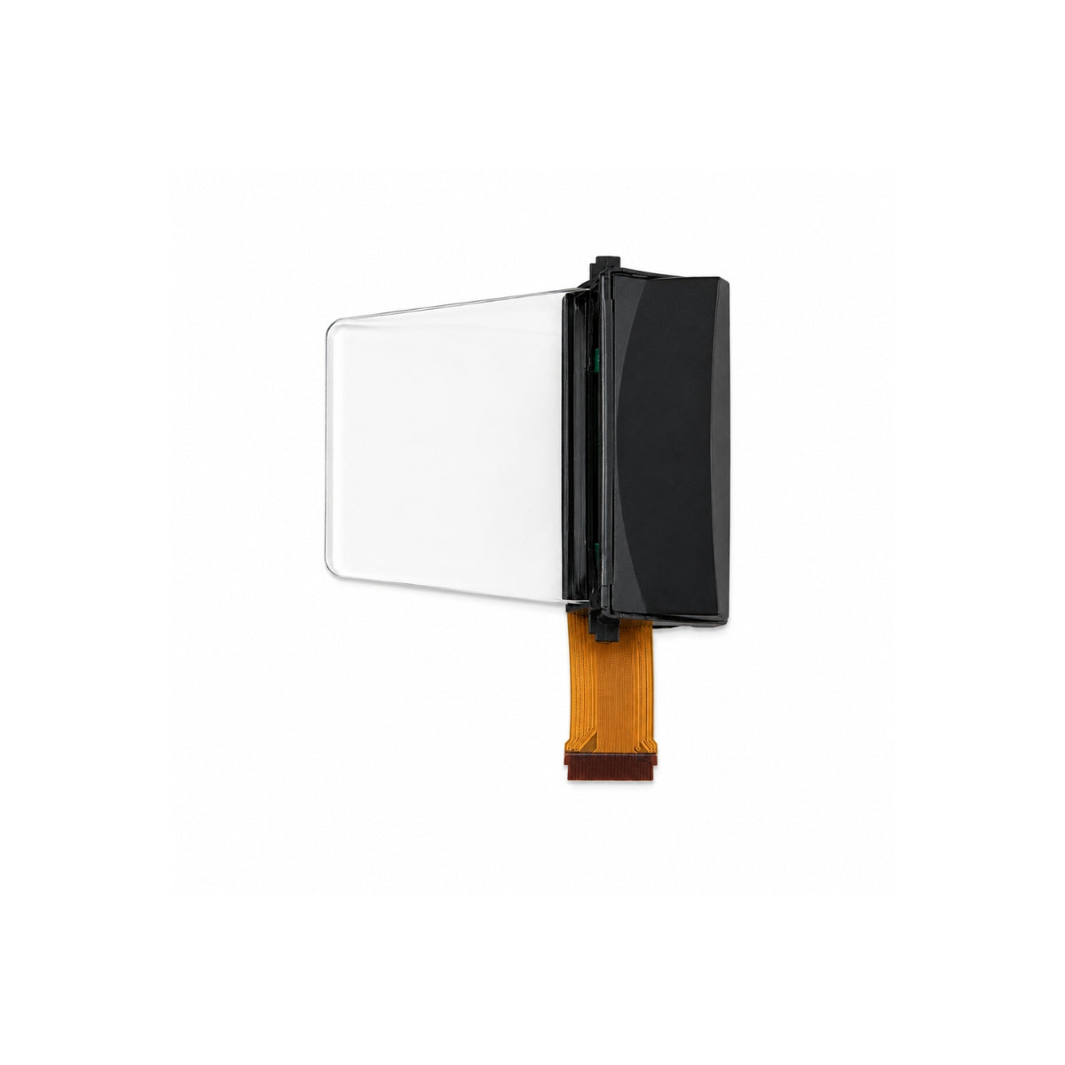
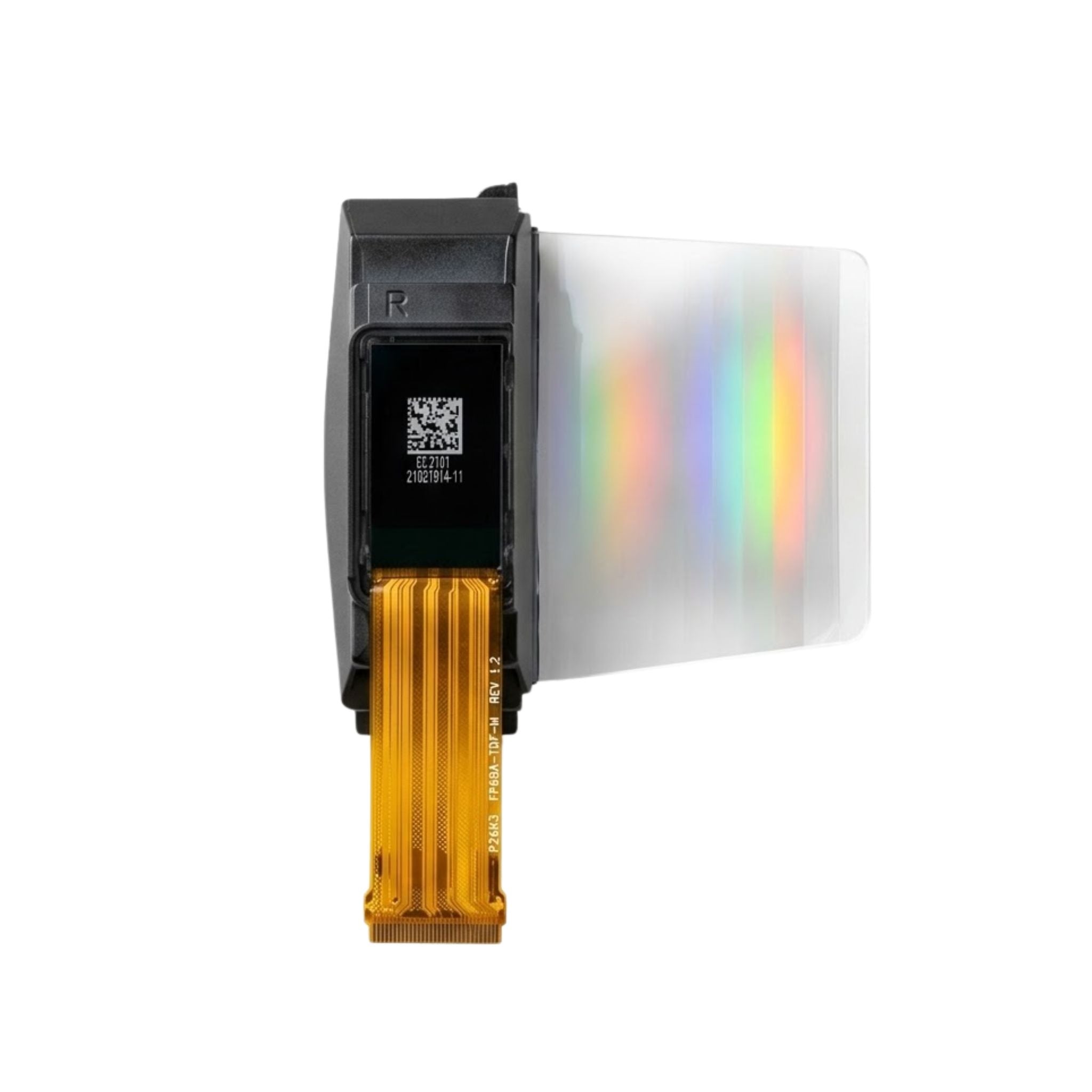


6.01" AMOLED Display 1080×2160 High Resolution – MIPI Interface
Resources & Downloads
SKU DMKDO06001BCA
6.01-Inch AMOLED Display Module — 1080 × 2160 Resolution and 4-Lane MIPI Interface
A portrait-format AMOLED display module with a 6.01-inch diagonal, 1080 × 2160 native resolution, a 68.256 × 136.512 mm active area and a 70.066 × 142.297 mm panel outline.
The available mechanical drawing provides panel dimensions, a 39-pin FPC assignment, operating-voltage values, temperature limits, controller references and dimensional tolerances. Electrical timing, initialization commands, optical performance and the active production controller revision must be confirmed before final design release.
6.01 Inch
Diagonal panel size
1080 × 2160
2,332,800 pixels
4 Data Lanes
D0, D1, D2 and D3 pairs
0.78 ± 0.15 mm
Specified panel thickness

Approximately 401.8 PPI
Calculated from resolution and diagonal size
1:2 Portrait Ratio
1080 horizontal × 2160 vertical pixels
39-Pin FPC
Display, touch, control, power and ground connections
Approximately 93.46%
Calculated active-area-to-outline ratio
Mechanical Drawing Specifications
The values below are taken from drawing DMKDO06001BCA, Parts No. 97060001A. The drawing revision information shows a model update dated 16 July 2024. Calculated values are identified separately.
|
Parameter |
Specification and Status |
|---|---|
|
Drawing Name |
DMKDO06001BCA |
|
Parts Number |
97060001A |
|
Revision Date Shown |
16 July 2024 |
|
Display Mode |
AMOLED |
|
Diagonal Size |
6.01 inches |
|
Native Resolution |
1080 × 2160 pixels |
|
Calculated Pixel Count |
2,332,800 pixels |
|
Calculated Pixel Density |
Approximately 401.8 PPI |
|
Active Area |
68.256 × 136.512 mm |
|
Panel Outline |
70.066 × 142.297 mm |
|
Panel Thickness |
0.78 ± 0.15 mm |
|
Unspecified Tolerance |
±0.2 mm |
|
FPC Pin Count |
39 pins |
|
Display-Controller Reference |
CH13721C is listed in the drawing. Confirm the current production revision before firmware development. |
|
Touch-Controller Reference |
FT3519 is listed in the drawing. Confirm the current production revision before touch-driver development. |
|
Compliance Statement |
The drawing states “RoHS compliant.” |
Mechanical Integration Parameters
The dimensional values support initial enclosure planning. Connector geometry, FPC bending limits, adhesive thickness and production tolerances must still be reviewed against the approved sample and latest controlled drawing.
0.905 mm Calculated Side Margin
Calculated as half of the difference between the 70.066 mm panel width and the 68.256 mm active-area width.
FPC Shipped Unfolded
The drawing states that the module is delivered with the FPC extended. Confirm the permitted bend area and bend radius before enclosure release.
Tolerance Stack-Up
Use the ±0.2 mm unspecified tolerance and 0.78 ± 0.15 mm thickness when defining housing clearance and adhesive compression.
Operating-Voltage Values
The mechanical drawing lists the following voltage values. It does not provide complete power sequencing, current consumption, discharge timing or regulator-ripple limits.
VCI: 2.5–3.6 V
Range stated in the drawing notes.
IOVCC: 1.65–3.3 V
Range stated in the drawing notes.
ELVDD: 4.6 V
Value stated in the drawing notes.
ELVSS: −3 V
Value stated in the drawing notes.
AVDD: 6.7 V
Value stated in the drawing notes.
Do not derive a production power sequence from these voltage values alone. Obtain the current electrical specification before applying power to engineering samples.
39-Pin FPC Assignment
Pin names below reproduce the labels shown in the mechanical drawing. Pin 27 is displayed as “REST” in the source drawing and is retained without reinterpretation.
|
Pin |
Symbol |
|---|---|
|
1 |
GND |
|
2 |
D0P |
|
3 |
D0N |
|
4 |
GND |
|
5 |
D1P |
|
6 |
D1N |
|
7 |
GND |
|
8 |
CLKP |
|
9 |
CLKN |
|
10 |
GND |
|
11 |
D2P |
|
12 |
D2N |
|
13 |
GND |
|
Pin |
Symbol |
|---|---|
|
14 |
D3P |
|
15 |
D3N |
|
16 |
GND |
|
17 |
TSP_INT |
|
18 |
TSP_RESET |
|
19 |
TSP_SCL |
|
20 |
TSP_SDA |
|
21 |
TSP_AVDD |
|
22 |
TSP_VDDIO |
|
23 |
AVDD |
|
24 |
AVDD_EN |
|
25 |
SWIRE |
|
26 |
TE |
|
Pin |
Symbol |
|---|---|
|
27 |
REST |
|
28 |
VDDIO |
|
29 |
GND |
|
30 |
ELVSS |
|
31 |
ELVSS |
|
32 |
ELVSS |
|
33 |
GND |
|
34 |
ELVDD |
|
35 |
ELVDD |
|
36 |
ELVDD |
|
37 |
MTP_PWR |
|
38 |
VCI |
|
39 |
DVDD |
Temperature Limits
−20°C to +70°C
Operating-temperature range stated in the drawing
−40°C to +80°C
Storage-temperature range stated in the drawing
Product-Level Testing Required
The stated temperature limits do not establish humidity, vibration, shock, thermal-cycle, ingress-protection or operating-lifetime performance.
Engineering Validation Before Design Release
The mechanical drawing supports early mechanical and connector planning. The following information is still required before production approval.
Electrical Documentation
Power-on and power-off sequencing
Operating, sleep and peak current
Lane rate, signal timing and initialization commands
Regulator ripple, tolerance and discharge requirements
Mechanical Confirmation
Connector model, height and insertion direction
Approved FPC bend radius and keep-out area
Adhesive, panel and enclosure tolerance stack
Protection from point loading, twist and FPC tension
Optical Specification
Typical and minimum luminance
Luminance uniformity and contrast ratio
Color coordinates, gamut and gamma
Refresh rate, response time and flicker limits
Production Control
Latest approved drawing and electrical datasheet
Golden-sample approval
Incoming inspection requirements
Hardware, firmware and lot traceability
Data Status and Specification Control
Directly Shown in the Drawing
Display mode, size, resolution, panel dimensions, thickness, voltage values, temperature ranges, pin assignment, controller references, parts number, revision information and RoHS statement.
Calculated from Published Values
Pixel count, approximate pixel density, lateral side margin and rectangular active-area-to-outline ratio are mathematical calculations rather than separate factory test results.
Requires Current Supplier Confirmation
Production controller revision, touch-controller revision, optical performance, power consumption, interface timing, command sequence, reliability limits and mass-production availability.
View Mechanical Drawing & Confirm Integration Details
Review the complete DMKDO06001BCA mechanical drawing to confirm panel dimensions, FPC position, pin assignment, voltage values, temperature limits and dimensional tolerances.
Before PCB, enclosure or firmware release, confirm the current production controller revision and obtain the controlled electrical and optical specifications from the supplier.
View Complete Mechanical Drawing