



COG vs COB LCD Modules: Which One to Pick
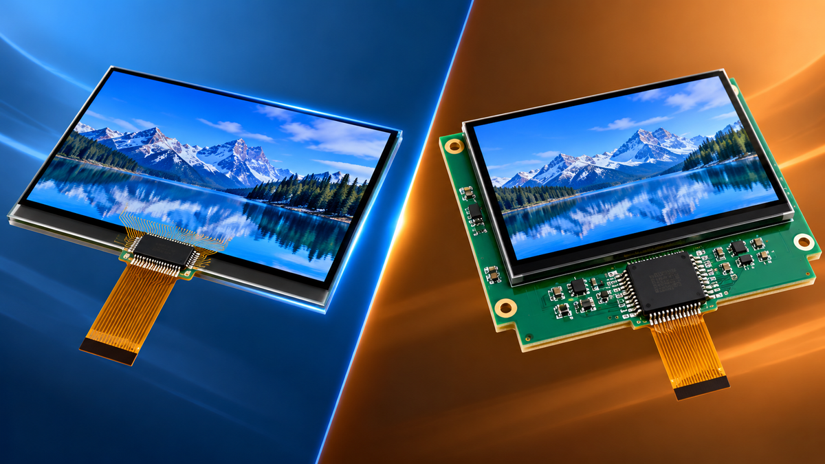
COG and COB describe where the driver chip lives: bonded to the glass (chip-on-glass) or mounted on a circuit board behind it (chip-on-board). The choice changes the module's thickness, its assembly process, whether it can be repaired, and how densely the display can be addressed. It is a mechanical and commercial decision more than a display-performance one — both structures can drive the same LCD.
Where the thickness differs
A COG module carries the die on the glass, so the board behind the display can be eliminated entirely, or reduced to a thin flex tail. The stack is roughly the glass, the polariser, the backlight and the adhesive. Assemblies in the low single-digit millimetres are routine.
A COB module keeps the driver on a PCB. The board, the package height and the connector all add to the stack. That extra volume is the price of the structure, and it is the first reason a project chooses COG — usually when the enclosure has no room to give.
Where assembly differs
COG assembly is a semiconductor process. The die is aligned to ITO traces, bonded with anisotropic conductive film under controlled pressure and temperature, and inspected optically. It happens in a module factory with bonding equipment, and it does not transfer to a general assembly line.
COB assembly is conventional electronics. The die is attached to the board, wire-bonded, glob-topped and then handled like any other SMT assembly. That makes it accessible to more suppliers, easier to prototype, and easier to rework before the module is finished.
The practical consequence is lead time and flexibility. A COG design is locked once the bond tooling exists; a COB design can be re-spun with board changes alone.
Where repairability differs
A bonded COG die is not field-replaceable. If it fails, the module is replaced. For a low-cost product that is acceptable; for equipment that must be serviced in the field, it becomes a lifecycle cost that has to be counted.
COB failures can, in principle, be reworked — the board is accessible, the package is a component. Whether that matters depends on the product's service model, not on the display itself.
Contact density sets the resolution ceiling
This is the least discussed difference and often the decisive one. A COG bond can place pads at a finer pitch than a connector can, so more segments or a larger matrix can be driven without adding interconnect hardware. As resolution grows, the connector on a COB design becomes the limiting and increasingly expensive part.
For character displays and small graphic panels the difference rarely binds. For a dense graphic display in a small outline, COG is usually the only practical route.
Where the cost crossover sits
COG wins on unit cost at volume: fewer components, no board, less assembly labour. It loses at low volume, where the bonding set-up and tooling cannot be amortised, and it loses where the module is large, because bond yield and handling cost rise with substrate area.
The crossover is not a fixed number of units; it depends on the display size, the driver's pad count and how much of the board the COB design would otherwise need. The honest comparison is a full landed cost at the actual order quantity — including the board, the connector, the assembly time and the yield — rather than a unit price for the display alone.
What each structure does to the enclosure
The choice propagates into the mechanical design more than most comparisons admit. A COG module with a flex tail expects the host board to sit behind or beside the display, connected by a tail that folds once and stays folded. That imposes a bend-radius requirement, a tail-length requirement and a keep-out zone where the tail must not be pinched by the housing.
A COB module expects the opposite: the board is part of the module, so the host connects to a header or a connector at a defined position, and the module's own depth has to be accommodated in the enclosure. In a thin handheld the COG arrangement wins on space; in a bench instrument with a roomy case, the COB arrangement wins on assembly simplicity.
Where the decision usually lands
Three patterns cover most projects. A high-volume consumer device with a small display and a fixed design chooses COG: unit cost and thickness dominate, and the design will not change after tooling. A low-volume industrial instrument chooses COB: the design may be revised, serviceability matters, and the volume never justifies bonding tooling.
The third pattern is the one that catches teams out: a medium-volume product with a dense small display, where COG is chosen for interconnect density but the volume is too low to amortise the set-up. In that case the honest options are to accept a higher unit price, to redesign for COB with a wider bezel, or to use COF as the middle route.
The two failure paths are different
COG field failures cluster around the bond: a cracked die, a lifted bond, a damaged ITO trace near the bond area. They usually present as missing rows or columns, or as a display that works until the enclosure flexes.
COB failures cluster around the board and the wire bonds: a solder joint, a connector, a glob-top crack. They present more variably and are more often repairable.
Knowing which path applies changes the test plan. A COG module benefits from a flex test at the FPC and a bond-area inspection; a COB module from a connector and solder-joint inspection.
How to choose
- Choose COG when the stack must be thin, the volume is high, the resolution needs dense interconnect, and the module is treated as a replaceable part.
- Choose COB when the volume is low, the design may still change, serviceability matters, or the display is large.
- In both cases, specify luminance, contrast and uniformity with their measurement basis, standardised in ISO 9241-307[1].
COG modules are listed in the COG LCD collection, and character and graphic formats across both structures under character LCD and graphic LCD displays.

COG and COB differ in where the driver sits, and that decides thickness, assembly route, repairability and the interconnect density ceiling. Choose COG for thin, high-volume, high-density designs and COB for low volume, design flexibility or field serviceability — and compare full landed costs, not display prices.
References
- ISO 9241-307:2008 — Ergonomics of human-system interaction — Part 307: Analysis and compliance test methods for electronic visual displays. International Organization for Standardization. https://www.iso.org/standard/40102.html
더 읽기
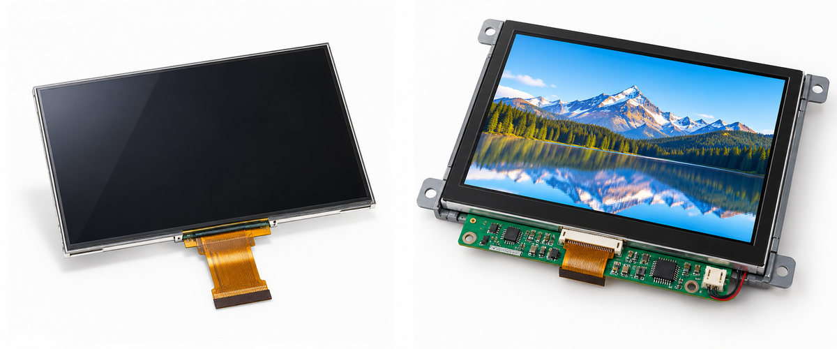
An LCD panel quote usually covers the basic display assembly. An LCD module can include quite a bit more: the backlight, driver IC, FPC, frame, touch.
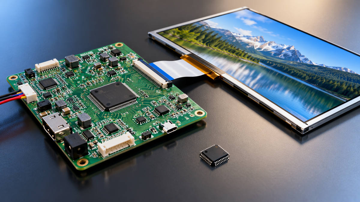
A display driver IC and a controller board are not two parts competing for the same slot. The driver IC writes pixel voltage onto the glass, and the panel.
댓글 남기기
이 사이트는 hCaptcha에 의해 보호되며, hCaptcha의 개인 정보 보호 정책 과 서비스 약관 이 적용됩니다.