









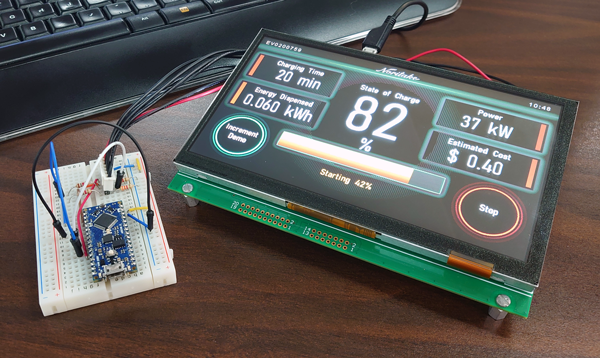
Do TFT LCD Modules Support Touch Easily
Yes. Most TFT LCD modules can be supplied with a touch panel laminated or gapped to the front, and many catalog parts ship as touch-ready assemblies. Whether the integration feels easy depends less on the LCD than on three things: whether the module's mechanical stack was designed for a touch layer, how well the controller and its driver are documented, and whether the sensing technology suits the operating environment.
How the touch layer attaches
There are two families of construction. In an out-cell design the touch sensor is a separate sheet — glass or film — bonded to the front of the display cell. This is the most common arrangement for industrial and instrument modules because the display and the touch sensor can be sourced, and replaced, independently.
In an on-cell or in-cell design the sensing electrodes are formed on the display's own substrate or integrated into the cell. The result is thinner and avoids one optical interface, but it ties the buyer to the panel maker's controller and offers little flexibility on the sensing pattern. For low-volume equipment, out-cell usually wins on availability.
The bond itself matters. A fully laminated stack removes the air gap and with it one pair of reflective surfaces, which improves contrast under bright ambient light. An air-gap assembly is cheaper and easier to rework, but it adds parallax between the touch surface and the image, so a finger appears offset from the icon it is pressing when viewed off-axis.
Resistive and capacitive
Resistive sensing works by pressing two conductive layers together. It responds to a stylus, a gloved finger or a fingernail, consumes little power, and tolerates a plastic front surface. The trade-off is that it needs physical force, shows wear at heavily used points, and generally reports one contact at a time.
Projected capacitive sensing measures a change in capacitance and needs no force at all. It supports gestures and multiple contacts, and its glass front resists scratching better. It also demands a conductive object — a gloved hand may not register, and a drop of water can be read as a touch unless the controller includes water rejection.
| Property | Resistive | Projected capacitive |
|---|---|---|
| Actuation | Pressure from any object | Conductive contact |
| Multi-touch | Usually single point | Multiple points |
| Front surface | Film, prone to wear | Glass, more durable |
| Gloves and water | Tolerant of both | Needs specific controller features |
| Optical penalty | Higher haze, extra layers | Lower, especially when laminated |
| Typical fit | Industrial HMI, handheld terminals | Consumer devices, kiosks, medical |

The optical cost
Every layer placed in front of the display reflects some light and absorbs some. A touch sensor adds at least one substrate and one adhesive layer, and each interface returns a small fraction of the ambient light toward the viewer. The visible result is a slightly greyer black and a dimmer image, which is why touch modules often need a brighter backlight to reach the same on-screen appearance as a non-touch equivalent.
This is also why brightness and contrast figures should be compared only when measured the same way. Contrast depends on the viewing geometry and the ambient illumination during measurement, and a figure quoted without those conditions cannot be compared across suppliers[1]. Anti-reflection and anti-glare coatings on the front surface recover some of the loss, and index-matched bonding adhesive recovers more.
Controller and driver support
The touch controller is a small microcontroller with its own firmware. It reports coordinates over I2C, SPI or USB, and the host needs a driver that understands its report format. On Linux, most capacitive controllers are handled by the kernel's input subsystem once the correct device tree entry exists; on a bare-metal project the vendor's initialization sequence and register map are essential.
Ask three questions before committing. Does the supplier provide the initialization code, or only a datasheet? Is the controller's I2C address configurable, so two devices can share a bus? And is there a documented calibration or tuning procedure for the cover glass thickness you intend to use? A controller tuned for a thin film will misbehave behind a thick glass panel unless its sensitivity is retuned.
Mechanical integration
The flex tail carrying the touch signals needs a route that does not cross the display's own tail at a sharp angle, and it needs strain relief at the connector. Grounding is not optional: the touch sensor references the same chassis as the display, and a floating bezel produces erratic readings.
If a cover glass sits above the sensor, the bonding method changes the mechanical behaviour of the whole stack. Full lamination stiffens the assembly and improves optical performance but makes repair impossible; a gasket-sealed air gap allows service but admits parallax and condensation. For equipment that will be washed down or used outdoors, the seal around the touch tail exit is often the first thing to fail.
Noise and false touches
Capacitive sensing measures very small charge changes, so it is sensitive to nearby noise. Switching power supplies, backlight boost converters and the display's own gate lines are the usual culprits. Symptoms include jitter at the edges of the panel, phantom contacts when a charger is connected, and missed touches during bright content.
Mitigations are well established: keep the touch tail away from the backlight converter, ground the display frame to the chassis at more than one point, and use a controller with frequency hopping so it can move away from a noisy band. If the panel sits behind a metal front plate, the plate needs a defined ground path or the sensor's baseline will drift with humidity.
A workable bring-up sequence
- Power the display alone and confirm the image before connecting the touch flex.
- Read the controller's ID register over the bus; a wrong address is the most common first failure.
- Load the vendor initialization table, then verify raw coordinate counts change across the full active area.
- Run the calibration routine with the final cover glass in place, not with the bare sensor.
- Test at the temperature extremes you specified, and repeat the test with the charger connected.
That sequence separates display faults from touch faults, which saves the most time in practice. Modules listed in the TFT display collection are available with or without a bonded touch layer, and the industrial display range includes resistive assemblies intended for gloved operation.
Where it stops being easy
Touch becomes a design problem rather than a purchase when the panel is large, when the front surface is thick or curved, when the device must work wet, or when the enclosure is metal with an undefined ground. In those cases the sensing technology, the controller tuning and the mechanical stack have to be settled together before any sample is ordered.
For a normal instrument panel with a laminated sensor, a documented controller and a plastic or thin-glass front, adding touch is closer to buying a part than to a project. The difference lies almost entirely in how much of the stack the supplier has already qualified.
References
- ISO 9241-307:2008 — Ergonomics of human-system interaction — Part 307: Analysis and compliance test methods for electronic visual displays. International Organization for Standardization. https://www.iso.org/standard/40102.html
더 읽기
When selecting brightness for your graphic OLED module, factor in ambient light: aim for 100-200 nits in well-lit rooms (e.g., near windows) to combat.
Yes, PMOLED modules prove durable for industrial use: they typically last 50,000 to 100,000 hours (outperforming many LCDs), withstand extreme.
댓글 남기기
이 사이트는 hCaptcha에 의해 보호되며, hCaptcha의 개인 정보 보호 정책 과 서비스 약관 이 적용됩니다.