









How to Extend TFT LCD Lifespan | Operating Conditions, Maintenance
Most TFT LCD modules do not fail in the glass; they fail in the backlight or at the seal. Extending life means keeping the LED junction cool, driving the backlight at a derated constant current, holding humidity below the condensing point, respecting the power sequence, and cleaning with solvents that do not attack the polariser.
Which part wears out
The liquid crystal cell itself is chemically stable when it stays inside its rated temperature range. The wear-out items are the LED backlight, whose output declines with junction temperature, and the polariser, which yellows and shrinks with heat and absorbs moisture at the edges.[2]
Datasheet life figures of tens of thousands of hours are not a guarantee for your enclosure. They assume a stated ambient, a stated drive current and a stated end-of-life criterion—usually the point where luminance has fallen to a fixed percentage of the initial value. Change any of those and the number moves.
Temperature
Heat is the dominant variable. Above the rated ambient, LED efficiency falls and the phosphor ages faster, so the same drive current produces less light and more heat, which is a loop that runs away if the thermal path is poor.
The polariser is the second victim. It is a stretched PVA film with iodine or dye, laminated between protective layers, and it is the least heat-tolerant part of the stack. Long exposure to high temperature drives iodine migration and shrinkage, visible first as a yellow cast in the white field and later as corner light leakage where the film pulls away from the glass.
Mechanical stress belongs here too. Glass, aluminium bezel and plastic housing expand at very different rates, so a bezel that clamps the panel without clearance will squeeze it as the unit warms. The result is mura—cloudy patches near the edges—and in severe thermal shock the glass or the ITO traces can crack.
Humidity and condensation
Humidity acts on the conductive parts. Above roughly 80% relative humidity—commonly the upper limit of a module qualification—an adsorbed water film bridges adjacent traces on the PCB or FPC, and with a bias applied, metal migrates from cathode to anode as dendrites. At fine pitches a dendrite can close the gap and short the driver within a few hundred hours.
Condensation is worse than steady humidity because it delivers liquid water. A unit moved from a cold store into a warm, humid room will be below the dew point, and powering it up while droplets sit on the board is a direct short. Let the unit reach room temperature in its bag before applying power, and use conformal coating where the cycle cannot be avoided.
At the glass edge, moisture entering the sealant attacks the ITO electrodes. The damage shows as a column that will not light, and it is not recoverable.

Supply and power sequence
Logic supply tolerance is narrow. A 3.3 V rail that sags below the undervoltage threshold will reset the driver, and a transient above the absolute maximum can break down the gate oxide. Ripple on the analogue supply shows up as faint noise or water-ripple patterning on a flat grey field, which is a useful diagnostic image.
The order of events matters more than the absolute values. Apply logic power, allow the driver to initialise, then send the video signal, then enable the backlight; reverse the order on shutdown. Sending data into an unpowered chip invites latch-up through the input protection diodes.
Inrush current at switch-on is the other common cause of field failures. Empty filter capacitors look like a short for a few hundred microseconds, enough to trip a fuse or pull the system rail down and restart the host. A soft-start or current-limited front end removes the problem at low cost.
Backlight drive
Drive the LED string with constant current, not constant voltage. The forward voltage of an LED falls as it warms, so a fixed voltage produces a rising current and a rising temperature—the classic thermal runaway path.
Dimming method affects both life and appearance. Many modules dim by PWM, chopping the current at a fixed frequency; others use analogue current reduction, and a hybrid of the two is common for wide dimming ranges. PWM holds colour better at low levels but can produce audible noise from ceramic capacitors or visible strobing in moving subjects, while analogue dimming is flicker-free but shifts colour at very low currents. Check the dimming frequency and the minimum duty cycle against the camera or sensor the product will be used with.
Derating is the cheapest reliability measure available. Specify a backlight capable of more than the target luminance and run it below maximum current, and add temperature feedback so the driver reduces output when the NTC near the LEDs passes its threshold.
Cleaning and handling
Dust is abrasive. Blow loose particles off before any cloth touches the surface, then wipe with a clean microfiber cloth in one direction, lifting the cloth rather than scrubbing in circles. Paper products contain wood fibre hard enough to leave micro-scratches that accumulate into a hazy surface.
Water quality matters as much as technique. Tap water leaves mineral scale when it dries; deionised water does not. If a solvent is needed, dilute isopropyl alcohol to about half strength with deionised water and apply it to the cloth rather than the screen. Spraying the panel lets fluid wick into the bezel gap and reach the COF bond, which is the beginning of an ITO corrosion failure.
Avoid ammonia-based glass cleaners, acetone, and ethanol-heavy disinfectant wipes. Alkaline cleaners attack the iodine in the polariser, and strong solvents can craze the polycarbonate bezel. Press hard enough only to maintain contact: the spacers that hold the cell gap are small, and a point load can leave a permanent ripple.
A maintenance schedule
Inspect every three to six months: tighten mounting screws, clear ventilation paths, and check for corner yellowing or edge bubbles, which are early signs of polariser degradation. Log the backlight current and the luminance at a fixed setting, measured the same way each time[1]—a slow decline is normal, a sudden step usually means a driver or connector problem.
For cabinets that run continuously, schedule a dark screen period or a lowered brightness at night. It costs nothing and removes a large share of the thermal load. Modules specified for wide temperature and long availability are listed under industrial displays, with standard parts under TFT LCD modules and chip-on-glass variants under COG LCD modules.
Lifespan is a system property, not a panel specification. Cool the LEDs, keep water out of the seal, sequence the power correctly and clean without solvent attack; the datasheet number then becomes something the product can actually reach.
References
- ISO 9241-307:2008 — Ergonomics of human-system interaction — Part 307: Analysis and compliance test methods for electronic visual displays. International Organization for Standardization. https://www.iso.org/standard/40102.html
- Hilsum, C. (2010). Flat-panel electronic displays: a triumph of physics, chemistry and engineering. Philosophical Transactions of the Royal Society A, 368(1914), 1027–1082. https://doi.org/10.1098/rsta.2009.0247
더 읽기
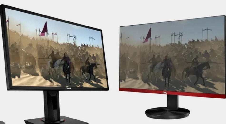
IPS panels, with their 178° wide viewing angle and 99% sRGB color gamut, far surpass ordinary TFT (TN) panels in color accuracy, making them suitable for.

PMOLED utilizes an orthogonal matrix of anodes and cathodes, employing a progressive scanning method to instantaneously activate pixels with a 1/N duty.
댓글 남기기
이 사이트는 hCaptcha에 의해 보호되며, hCaptcha의 개인 정보 보호 정책 과 서비스 약관 이 적용됩니다.