


OLED Module Cost Factors | Size, Resolution
The cost of OLED modules increases non-linearly with size; 65-inch large screens have a unit price far higher than mobile phone screens due to significant cutting losses.
High resolution (>400 PPI) requires expensive Fine Metal Masks (FMM), and for every 5% drop in yield, the cost surges.
Design must optimize layout based on glass generation line (e.g., Gen 6) specifications to reduce the allocated cost per unit by maximizing substrate utilization.
Size
Taking the globally common Gen 8.5 Line (2200mm × 2500mm) as an example, cutting 55-inch panels yields 6 units, with glass utilization exceeding 90%;
However, cutting 65-inch panels only yields 3 units, causing utilization to drop to 64%. This leads to a surge of over 40% in equipment depreciation and material waste allocated per inch.
Furthermore, for every 10% increase in display area, the probability of module scrapping due to particle contamination rises by approximately 15%-20% according to Poisson distribution, forcing manufacturers to reserve higher allowances for defective goods in the BOM.
Mother Glass Utilization
Production Line Size Hard Metrics
OLED Evaporators and Steppers are designed for specific glass sizes and cannot be changed at will.
Choosing which size of screen to cut on which generation of production line is the first step in determining cost.
Glass sizes corresponding to different production line generations are as follows:
| Generation (Gen) | Glass Size (mm) | Primary Cutting Target | Typical Cutting Case |
|---|---|---|---|
| Gen 6 | 1500 × 1850 | Smartphones, Smartwatches | ~200 units of 6-inch phone screens |
| Gen 8.5 | 2200 × 2500 | TVs, Monitors (IT) | 6 units of 55-inch TV screens |
| Gen 10.5 | 2940 × 3370 | Super-large TVs | 8 units of 65-inch TV screens |
If one forcibly cuts 13-inch tablet screens on a Gen 6 line primarily intended for phones, although technically feasible, the layout will result in a large number of unusable corners.
Similarly, the Gen 8.5 line is best suited for 55-inch (cutting 6 units, utilization 90%+). If used to cut 65-inch (cutting 3 units), the remaining glass area is as high as 36%.
This 36% of glass represents not only material waste but also takes away an equivalent proportion of expensive organic luminescent materials, gases, and machine running time.
Layout Geometry Calculation
As average TV sizes migrate towards 65 inches and 75 inches, Gen 8.5 lines face immense efficiency pressure.
Cutting efficiency comparison using Gen 8.5 (2200mm × 2500mm) as an example:
-
55-inch (1204mm × 680mm):
- Layout method: 2 × 3 arrangement.
- Output quantity: 6 units.
- Utilization: Approx. 91%. This is why Gen 8.5 is called the "Golden Line"—there is almost no waste.
-
65-inch (1428mm × 803mm):
- Layout method: Limited by the glass short side (2200mm), it can only cut 1 unit horizontally and 3 units vertically (or 2 units depending on margins). Usually, to ensure process margins, only 3 units can be cut.
- Output quantity: 3 units.
- Utilization: Approx. 64%. This means for every $100 invested in substrate and materials, $36 turns directly into waste.
-
98-inch and above:
- Layout method: 1 unit.
- Utilization: Usually below 60%. The pricing of this size is often more than ten times that of a 55-inch, not just because of the large area, but because a single product must bear the manufacturing cost of the entire mother glass.
MMG Technology to the Rescue
To solve the low efficiency of 65-inch cutting on Gen 8.5 lines, the industry adopted MMG (Multi-Model Glass) hybrid cutting technology.
- Combination Logic: After cutting 3 units of 65-inch panels, the remaining corner areas are used to cut 2 units of 32-inch or 55-inch panels.
- Data Change: Through MMG, the comprehensive glass utilization for cutting 65-inch on Gen 8.5 can be improved from 64% to over 85%.
-
Hidden Costs: Although material utilization improves, MMG is not without cost.
- Mask Cost: Requires designing two different sets of pixel lithography patterns, increasing the manufacturing and maintenance fees for Masks.
- Takt Time: The backend cutting and testing processes become complex because different sizes of products need to be sorted, which may reduce the line's total monthly throughput.
Waste Margins That Must Be Reserved
In actual manufacturing, the physical edge of the mother glass is an absolute "forbidden zone," and this loss is rigid.
- Clamp Margin: When production equipment transports glass, mechanical arms or rollers need to contact the glass edge. Usually, a non-film-forming area of 5mm - 10mm must be reserved on the four sides of the glass; no circuits can be manufactured in this area.
- Test Pattern Area (TEG & PCM): To monitor yield, test circuits (Test Element Group) and process control monitor modules (Process Control Monitor) must be made in the gaps between panels or at the edges.
- Seal & Scribe Line: A path for laser cutting and an area for applying encapsulation adhesive to prevent water and oxygen intrusion must be reserved around each screen. For flexible OLEDs, circuit space for the Bending Area is also needed.
These Process Margins usually make the actual area available for layout 5% - 8% less than the theoretical area.
Depreciation Allocation
The impact of glass utilization on cost is ultimately reflected in the allocation of extremely expensive equipment depreciation fees.
A Gen 8.5 OLED factory with a monthly capacity of 30,000 substrates (30K/Month) typically has an investment volume between $3 billion - $5 billion. Equipment depreciation is usually calculated over 5 years.
- High Utilization Scenario: If utilization is 95%, every second the machine runs is producing salable area, and the depreciation fee allocated per module is at the lowest level.
- Low Utilization Scenario: If utilization is 60%, it means 40% of the machine running time, electricity, and special gases in the factory are processing waste that will eventually be thrown away. These wasted Machine Hours must be borne by the 60% good products.
Defect Amplification Effect
Calculating the Yield Bill
Yield calculation follows the Poisson Distribution model. The simple logic is: the larger the panel area, the higher the probability of hitting "random defects."
Formula logic: Y = e-AD
- A (Area): The display area of the screen.
- D (Defect Density): The average number of defects per square meter.
Assume the factory cleanroom control level is 0.5 Killer Defects per square meter.
| Screen Type | Size (Inch) | Area (m²) | Calculation Logic | Theoretical Yield (%) |
|---|---|---|---|---|
| Smartwatch | 1.5 | 0.0007 | Area is extremely small, almost never hits defects | ~99.9% |
| Smartphone | 6.7 | 0.011 | e-0.1 ≈ 0.904837 | ~99.4% |
| Monitor | 27 | 0.2 | e-0.1 | ~90.5% |
| TV | 65 | 1.16 | e-(0.2×0.5) | ~56.0% |
| Giant TV | 83 | 1.9 | e-(1.9×0.5) | ~38.7% |
Data shows that under the same environment, simply increasing the area from a phone to a TV causes the yield to drop from near-perfect to failing.
For an 83-inch panel, for every 10 units produced, 6 might be scrapped directly.
To cover the cost of these 6 units, the remaining 4 good units must be priced extremely high.
One Bad Unit Ruins the Whole Sheet
OLED manufacturing is performed on a huge Mother Glass.
The cruelest aspect of defect amplification is: Defect distribution is random, but the cutting grid is fixed.
Imagine a Gen 8.5 (5.5 m²) mother glass with 5 particles of dust scattered randomly on it.
-
Cutting Phone Screens (Cutting 500 units):
- These 5 dust particles fall into at most 5 different phone screen areas.
- Result: 5 scrapped, 495 harvested.
- Loss Rate: 1%. This has almost no impact on cost.
-
Cutting TV Screens (Cutting 6 units of 55-inch):
- If these 5 dust particles are widely dispersed, there is a high probability they will fall into 5 different TV screen areas respectively.
- Result: 5 scrapped, only 1 harvested.
- Loss Rate: 83%. The ROI for this mother glass is almost zero.
This is why large-size OLED panels have much stricter requirements for manufacturing environment cleanliness (Cleanliness Class) than small sizes.
Phone production lines might allow Class 100 (no more than 100 particles of 0.5 microns per cubic foot), while large-size lines usually require local Class 10 or even lower. The cost of such environmental control is itself astronomical.
How Dust Destroys Pixels
The "defects" mentioned here mostly come from particle contamination during the organic material Evaporation process.
The thickness of the OLED emissive layer is usually only 100 - 200 nanometers. However, a tiny speck of dust (Particle) floating in the air might have a diameter of 1 - 5 micrometers.
- Short Circuit Risk: If the dust is conductive (like metal shavings), it will pierce the nanometer-thin organic layer, directly connecting the cathode and anode. Current will take this shortcut, causing the pixel to shine extremely bright and then burn out, or causing drive anomalies in the entire row of pixels.
- Dark Spot: If the dust is non-conductive, it acts like an umbrella blocking the evaporated organic molecules, resulting in no luminescent material depositing on the pixel below. Alternatively, it leaves tiny bubble channels on the Encapsulation layer, allowing water vapor and oxygen to slowly seep in. OLED organic materials are extremely sensitive to water and oxygen; once infiltrated, the dark spot will slowly expand like mold over time (Grow-in defects), eventually causing screen failure.
On a 65-inch screen with 4K resolution, there are 24 million sub-pixels.
If just 1 sub-pixel is hit by a 3-micrometer dust particle causing a short circuit, the entire panel is judged as Grade B or scrap.
Those Pits That Can't Be Fixed
Although panel factories have Laser Repair technology, it is not a panacea.
- Cut Repair: If a pixel is short-circuited and constantly lit (Bright Dot), a high-energy laser can cut the TFT circuit controlling this pixel. The result is that this pixel becomes a permanently unlit "Dark Dot." Industry standards usually allow a very small number of dark dots (e.g., 3-5) for large screens, but do not allow glaring bright dots.
- Spare Circuit: Some high-end designs bury spare circuits next to the pixel. If the main circuit breaks, the spare circuit can be welded using a laser.
- Repair Limit: For OLED, the biggest obstacle to repair is heat. The high temperature generated by the laser easily damages the surrounding organic luminescent material. Once material carbonization occurs, it forms an irremovable black spot. Therefore, many repair methods common in the LCD era fail on OLED.
Scrapping After Assembly Hurts the Most
Cost accumulation is like a snowball. If a defect is found just after the Panel is cut, the loss is only the glass and evaporation materials.
But many tiny defects are hard to find during initial Cell Test and are often only exposed during the Aging process after attaching the driver chip, FPC board, or even backplane structures.
The loss in Module Yield is fatal:
- Added Value Loss: At this point, what is scrapped is not just a piece of glass, but also the attached Source Driver IC. For an 8K large screen, 24 expensive COF chips might have been attached. Scrapping a module means throwing away these 24 chips.
- Rework Cost: Although theoretically chips can be removed and reused, the process of removing ACF (Anisotropic Conductive Film) is very tedious and easily damages chip pins. In reality, for efficiency, many module factories choose to scrap the whole unit once panel defects are found after bonding, because the labor cost of disassembly is more expensive than the chip itself.
- According to industry estimates, the financial loss of a 65-inch OLED panel scrapped at the module backend is 1.5 to 2 times that of a panel scrapped at the frontend.
Driver Chip Increment
The Math of Pixel Channels
Each sub-pixel (Red, Green, Blue) on an OLED screen requires an independent voltage signal to control brightness.
This becomes a simple division problem: Total Channels ÷ Channels per Chip = Number of Chips.
Taking mainstream 4K (3840 × 2160) resolution as an example:
- Horizontal Pixels: 3840.
- Sub-pixel Channels (RGB): 3840 × 3 = 11,520 data channels.
Current driver chips are not infinitely long; their physical pin count is limited. Industry standard Source Driver IC channel specifications are usually 960 ch, 1024 ch, or 1280 ch.
| Resolution Spec | Total Data Channels | Using 960ch Chip (Units) | Using 1280ch Chip (Units) | Cost Implication |
|---|---|---|---|---|
| FHD (1920×1080) | 5,760 | 6 | 5 | Entry-level large screen, chip cost controllable |
| 4K (3840×2160) | 11,520 | 12 | 9 | Mainstream config, driver IC cost doubles |
| 8K (7680×4320) | 23,040 | 24 | 18 | Chip count explodes, higher spec IC needed |
For a 65-inch 4K OLED panel, covering these 11,520 channels typically requires 12 960-channel driver chips arranged at the bottom edge of the screen.
If you go for 8K, this number doubles directly to 24 chips.
Every chip costs money to buy, takes up PCB space, and consumes power.
Distance Signals Can't Travel
Here lies a stumbling block in physics: RC Delay (Resistance-Capacitance Delay).
The larger the screen, the longer the internal traces.
- Resistance (R): The longer the metal wire, the greater the resistance.
- Capacitance (C): Parasitic capacitance between the wire and surrounding circuits increases with length.
When the voltage signal runs from the top of the screen to the bottom, or from the chip to the pixel, the signal waveform becomes "sluggish" (Rise time slows down) due to RC delay.
If the screen size exceeds 55 inches, signals driven by a single chip struggle to complete charging and discharging accurately within the extremely short scan time (e.g., only a few microseconds at 120Hz).
To solve this, large-size panels must adopt a Zone Governance strategy:
- Physical Partitioning: The screen is sliced horizontally into 12 or more regions, each responsible by an independent Source IC. This way, each chip only needs to cover a very short horizontal distance.
- Dual Driving: For super-large sizes (like over 85 inches) or high refresh rate panels, driver chips may need to be placed on both the top and bottom of the screen, or Gate Drivers placed on both left and right sides.
Expensive Tape COF
OLED screens for phones usually stick the driver chip directly on the glass (COG, Chip on Glass) or plastic substrate (COP, Chip on Plastic) because the screen is small and heat dissipation pressure is low.
But at the level of TVs or monitors, COF (Chip on Film) has become a standard and expensive configuration.
- What is it: COF involves encapsulating the driver chip on a flexible yellow circuit board (FPC tape) first, and then pressing this "tape" onto the screen edge.
-
Why use it:
- Heat Dissipation: Large-size driver chips generate huge heat when working. Sticking them on glass dissipates heat slowly, easily causing local overheating and burn-in. COF can conduct heat away.
- Narrow Bezel: COF can be bent, hiding the chip behind the screen to achieve a true bezel-less design.
-
Cost Pit: COF packaging is much more expensive than COG.
- Tape Material: This high-precision copper-clad polyimide film itself is a high-priced consumable.
- Gold Usage: Connecting the chip to the film requires gold balls or gold wires. With the increase in pin count (e.g., 1280 pins), gold usage is a tangible cost.
Interfaces Must Upgrade
As the number of chips goes from 1 to 12 or even 24, commanding these chips becomes a major issue.
- Mini-LVDS Bottleneck: Old interface protocols lack sufficient bandwidth at large sizes and high resolutions. It's like one teacher managing one class versus one teacher trying to command 24 branch venues simultaneously; shouting (low-speed parallel bus) is no longer effective.
-
P2P High-Speed Interface: To achieve 4K 120Hz or even 240Hz on a 65-inch large screen, driver chips must support point-to-point high-speed transmission protocols like USI-T or iSP.
- Cost: Driver chips supporting P2P protocols have more complex wafer designs and larger Logic Die Sizes, with a unit procurement price typically 20% - 30% higher than ordinary chips.
- Timing Controller (T-Con): Furthermore, the "brain" controlling these 24 high-speed chips—the Timing Controller (T-Con)—also needs an upgrade. A T-Con worth a few dollars might not suffice, requiring a high-computing chip worth tens of dollars, or even two T-Cons working in cascade.
Invisible Loss in Mounting Time
In the factory, time is Throughput.
- Bonding Process: Each COF requires precise alignment and pressing (OLB, Outer Lead Bonding). The machine must grab the COF, align with cameras, press down with a thermal head, and hold pressure to cure.
-
Takt Drag:
- Mounting 1 chip (Phone): Done in a few seconds.
- Mounting 12 chips (TV): If the equipment operates with a single head, the time is directly ×12. If using multi-head parallel equipment, the investment soars.
- Once 1 chip is not mounted properly (alignment deviation or cold solder), the entire 65-inch module needs to go offline for Rework. Reworking large modules is not only extremely difficult (requiring chemical agents to dissolve ACF glue) but also very prone to breaking the expensive OLED panel.
Mask Gravity
The Catenary Physics Bill
No matter how tight you pull a rope, it will always sag in the middle. This is the Catenary phenomenon.
For Gen 6 lines (1.5m wide), this sag can usually be controlled at the micron level by forcibly pulling tight with a Tensioner.
But for Gen 8.5 (2.2m wide), the span increases by 50%, and the sag amount does not increase linearly but is proportional to the square of the span.
If left untreated, a 65-inch FMM can sag 100 - 200 microns at the center under its own weight. In OLED photolithography processes, the allowed tolerance is usually only 3 - 5 microns.
- Equipment Upgrade Fee: To suck this sagging mesh up tight against the glass, large evaporators must be equipped with complex Magnetic Plate systems. This system consists of thousands of independent electromagnetic units, requiring precise control of magnetic force in each area. This drives the cost of a Gen 8.5 evaporator straight to over $100 million.
- Cooling Cost: Magnetic plates generate heat when energized, while FMM is extremely sensitive to temperature (thermal expansion causes misalignment).
Blur Caused by Shadows
Even with magnetic attraction, large-size FMMs cannot fit the glass as perfectly as small ones. Tiny Gaps cause the Shadowing Effect.
OLED organic materials are heated and vaporized in a vacuum, flying towards the glass like a spray.
- Ideal State: FMM fits tightly against the glass, organic molecules pass precisely through holes, landing on designated pixel areas with sharp edges.
-
Sagging State: There is a 10-micron gap between FMM and glass.
- Color Mixing: Red light material runs into green light pixels, causing a drastic drop in Color Gamut or even obvious color shift.
- Yield Killer: This defect is unrepairable. Once large-area shadow color mixing occurs, the panel worth thousands of dollars can only be scrapped. In 65-inch panel production, yield loss due to poor FMM adhesion typically accounts for 20% - 30% of the total defect rate.
Sacrificed Aperture Ratio
To prevent that huge metal mesh from breaking or deforming too much, the design of large-size FMM must compromise. Engineers must insert thicker and wider metal Support Sticks / Ribs between pixels.
This is not just a structural issue but a direct economic loss:
- Dead Zone Expansion: The wider the metal support stick, the more light it blocks, and the smaller the effective light-emitting area (Aperture Ratio).
-
Lifespan Depreciation: If the aperture ratio drops from 40% to 30%, to maintain the same 1000 nits brightness, the remaining luminescent material must withstand higher Current Density.
- Consequence: Organic material aging accelerates, screen lifespan shortens.
- Cost Transmission: To maintain the warranty (Burn-in warranty), manufacturers can only procure more expensive top-tier organic materials with higher luminous efficiency (like Deuterated Blue material), or are forced to increase the thickness of the emissive layer, directly raising the BOM cost.
Expensive Fast-Moving Consumer Goods
FMM is made of a special Invar Alloy (Nickel-Iron), which has an extremely low coefficient of thermal expansion and is priced by the gram. On small-size lines, an FMM might be used thousands of times. But on large-size lines, the repeated pulling by gravity and magnetic force turns FMM into a "consumable."
- Metal Fatigue: Every time evaporation occurs, the magnetic plate sucks the FMM up, puts it down after evaporation, and the conveyor belt moves it away. This repeated bending and stretching causes plastic deformation in the metal mesh. Once the mesh hole position shifts by more than 2 microns, the entire mesh is useless.
- Cleaning Loss: After being used a few times, the edges of FMM holes get covered with organic material and must be cleaned. Large-size FMMs are structurally fragile, and the cleaning process easily causes wrinkles or breakage.
- Financial Impact: The price of a Gen 8.5 FMM Mask Set is between $300,000 - $500,000. If the lifespan is only half that of small sizes, it means the "mold loss fee" allocated to each 65-inch TV could be dozens of times that of a phone screen.
Why Most TVs Don't Use This Method
Precisely because the costs brought by FMM gravity issues are too staggering (low yield, short life, expensive equipment), mainstream large-size OLED TVs (like LG's WOLED technology) directly abandoned the FMM RGB process.
- Alternative: Use Open Mask (a blank mask without fine patterns).
- Logic: Since alignment is so hard, don't align. Stack Red, Green, and Blue materials directly together to emit white light, then use Color Filters to separate colors.
- Cost: Although avoiding the huge pit of FMM gravity, Color Filters block 60% - 70% of the light. To compensate for brightness, multiple light-emitting stacks (Tandem Structure) up to 2-3 layers must be manufactured, increasing material consumption by two times.
Resolution
Once PPI exceeds the industrial critical point of 400, manufacturing must introduce high-precision FMM (Fine Metal Mask) and LTPS/LTPO backplane technologies, leading to a 30%~50% increase in mask loss rate.
Simultaneously, the number of Driver ICs required for 4K panels is 4 times that of FHD, and with higher bandwidth requirements, this causes electronic component costs to rise significantly.
High-density pixels also amplify the defect rate caused by minute foreign particles, directly pulling down the final yield.
The Process Wall of PPI and FMM
Holes Too Small Cause Shadows
The working principle of FMM is like a funnel; organic material vapor passes through openings on the mask to deposit onto the substrate.
But the mask itself has thickness. When the Hole Size shrinks to near the mask thickness, the "Shadow Effect" appears.
During evaporation, the organic material Source does not enter vertically but has a certain Deposition Angle.
If the FMM is too thick and the aperture too small, the vapor gets blocked by the hole walls, causing insufficient thickness or blurred shapes at the pixel edges on the substrate.
- Aspect Ratio Limit: To reduce shadows, FMM thickness usually needs to be less than 50% of the sub-pixel width.
-
Data Comparison:
- When producing FHD (300-400 PPI) panels, Invar sheets with a thickness of 20-30 microns can be used.
- When producing QHD+ or 4K (>500 PPI) panels, sub-pixel spacing is extremely small, and FMM thickness must be cut to 10-15 microns or even thinner.
- Consequence: Making a metal sheet 10 microns thick (only 1/8 of a hair's diameter) vastly increases processing difficulty and breakage risk. Once thickness is not up to standard, the shadow effect reduces the Effective Emitting Area, lowering brightness.
Metal Too Thin Deforms Easily
FMM is a thin film suspended and stretched on a metal Frame. Being only a few microns thick, its own weight causes the center to sag.
- Sag Magnitude: Under Gen 6 (1500mm x 1850mm) dimensions, without any support, a 20-micron thick FMM can sag by millimeters at the center, while evaporation requires flatness errors not exceeding 3-5 microns.
- Tension Counteraction: To fight sagging, factories must apply immense Tension to the FMM, stretching it straight and welding it to the frame.
- Material Limit: This is exactly why only Invar Alloy (36% Nickel, 64% Iron) can be used; its Coefficient of Thermal Expansion (CTE) is extremely low (about 1.2 ppm/°C below 100°C). Even so, when thickness drops below 15 microns, the material's Yield Strength may not withstand the tension needed to straighten it, causing plastic deformation or tearing of the metal sheet.
Price List of Etching Precision
The way FMM is manufactured determines the cost basis. Processing techniques for different PPIs are completely different, with prices jumping in steps.
| Process Name | Applicable PPI Range | Processing Principle | Cost Estimate (Relative) | Defect Characteristics |
|---|---|---|---|---|
| Wet Etching | < 450 PPI | Using chemical solution to corrode metal | 1x (Benchmark) | Side walls not straight, have taper angle, aperture consistency average |
| Laser Drilling | 450 - 800 PPI | Using high-energy laser beam ablation | 3x - 5x | Heat-affected zone may cause micro-deformation, extremely high equipment depreciation |
| Electroforming | > 800 PPI | Electroplating metal growth on a mold | 5x - 8x | Extremely expensive, long production cycle, hard to make large sizes |
- Wet Etching Bottleneck: This is currently the most mature and cheapest process. But at high PPI, chemical solutions corrode not only downwards but also sideways (Side Etch), causing hole walls to thin, which leads to easy breakage and uncontrolled Pixel Pitch.
- Hybrid Process Cost: To maintain yield at QHD+ resolutions, some manufacturers use "Multi-Etching" or "Etching + Laser Trimming" hybrid processes. This directly doubles the process time, causing the procurement cost of a single FMM to soar from a few thousand dollars to tens of thousands.
Scrap After A Few Cleans
During evaporation, organic materials deposit not only on the glass but also on the FMM surface. As the deposition layer thickens, apertures become smaller or even blocked.
- Cleaning Cycle: Factories must periodically remove FMMs and clean them in organic solvents.
-
Lifespan Loss:
- Low PPI (FHD): Masks are thicker and structurally strong, potentially withstanding 50-80 cleaning cycles, with a total service life of up to 5000 evaporation Shots.
- High PPI (QHD/4K): Because masks are extremely thin (~15um) with densely packed holes (fragile skeleton), liquid turbulence or mechanical handling during cleaning easily causes tiny physical damage (like wrinkles, hole deformation). The cleaning life of high PPI FMMs is often only 20-30 times, reducing total life to 2000-3000 Shots.
- Cost Allocation Calculation: Assuming a high-precision FMM costs $20,000 and has a life of only 2000 shots. Then for every evaporation (producing one substrate), the FMM loss cost alone is $10. If a substrate cuts 60 phone screens, each screen bears about $0.16 just for mask loss.
Alignment Deviation Can't Be Fixed
At high PPI, FMM Alignment Accuracy requirements reach the limits of mechanical engineering.
- Alignment Tolerance: FHD panels have larger sub-pixel spacing, allowing 3-5 microns of alignment error. But in 4K panels, sub-pixel spacing might be only 10-15 microns, requiring alignment errors to be controlled within 1-2 microns.
- Thermal Deformation Variable: The temperature inside the evaporation chamber is usually 40°C - 60°C, and the organic source itself is a high-temperature heater. FMM undergoes thermal expansion in this environment. For a Gen 6 (long side approx. 1.85m) FMM, a 1°C temperature difference can cause a length change of 2-3 microns.
- Irreversible Scrap: Once Mask Shift occurs, evaporated red, green, and blue materials will mix (Color Mixing). This defect is located inside the emissive layer and cannot be repaired by laser welding like a circuit break. The entire panel with misalignment is directly scrapped, meaning all investment in the TFT Backplane and driver circuits is lost. For high PPI lines, yield loss due to alignment errors is usually between 3% - 5%.
The Multiplier Effect of Electronic Components
Chip Count Must Multiply
The most intuitive cost explosion occurs with the SDIC (Source Driver IC). Each sub-pixel of an OLED requires an independent drive channel.
-
Channel Count Math:
- FHD (1920 x 1080): Horizontal has 1080 pixel groups (RGB), i.e., 1080 × 3 = 3240 channels. If using a standard IC supporting 960 channels, only 4 chips are needed.
- 4K (3840 x 2160): Horizontal pixels double, channels soar to 3840 × 3 = 11520 channels. The same 960-channel IC now requires 12 chips.
- 8K (7680 x 4320): Channels reach 23040, chip demand increases to 24 chips.
-
Cost Stacking:
The price of an SDIC is usually between $0.3 to $0.6 (depending on process and packaging). Increasing from 4 to 12 chips raises the raw cost of driver chips alone by $3-5. -
Bezel Squeeze:
To cram 3 times the number of chips and traces into the same physical width, the Pad Pitch of the chip must be reduced. This forces IC manufacturers to use more expensive 28nm or 40nm high-voltage processes instead of cheaper 0.13um or 0.18um processes to reduce Die Size.
Transmission Speeds Fast Enough to Require Shielding
Resolution increase means an explosion in Data Throughput.
- FHD @ 60Hz data volume is about 3-4 Gbps.
- 4K @ 120Hz (10bit) data volume is as high as 25-30 Gbps.
This huge bandwidth pressure forces interface technology upgrades:
- Interface Generation: Ordinary mini-LVDS interfaces cannot handle 4K signals at all and must switch to USI-T, P2P (Point-to-Point), or high-frequency MIPI interfaces. These high-speed interface protocols often require patent fees.
-
Cabling & Shielding:
High-frequency signals generate severe EMI (Electromagnetic Interference) during transmission. To pass FCC/CE certification, the FFC (Flexible Flat Cable) connecting the T-Con board and Source Drivers must upgrade from ordinary cables to Impedance Controlled FFC, often requiring wrapping in expensive conductive cloth or absorbing materials. -
PCB Upgrade:
PCBs carrying these high-speed signals can no longer use ordinary FR-4 material; they may need to upgrade to High-Tg materials, and layer count increases from 2 layers to 4 or 6 layers to ensure signal integrity, raising PCB cost by at least 40%-60%.
Flash Memory for Data Must Be Bigger
OLED panels have an inherent characteristic: Mura (Brightness Non-uniformity). The brightness and color characteristics of each pixel are not consistent, so optical compensation (Demura) must be performed for each pixel before leaving the factory.
-
Data Volume Inflation:
- FHD: Compensation data for 2 million pixels might only need 8Mb - 16Mb of Flash storage space.
- 4K: 8.3 million pixels, compensation data volume multiplies by 4, plus High Bit Depth requirements, Flash capacity usually needs to upgrade to 64Mb or 128Mb.
- OLED Exclusive Algorithms: To prevent Burn-in, 4K panels need more complex real-time monitoring algorithms to record the "aging degree" of each pixel. This requires the T-Con (Timing Controller) to have stronger computing power and larger SRAM Cache. Ordinary T-Con chips might sell for $1, but high-end T-Cons with large SRAM and 4K Demura algorithms might sell for $3-5.
Bonding Process Tolerance is Gone
All driver chips need to be physically connected to the glass substrate. This process is called OLB (Outer Lead Bonding), usually using ACF (Anisotropic Conductive Film).
-
Pin Pitch Shrinkage:
On 4K panels, to squeeze tens of thousands of data channels into limited edges, the spacing between pins is compressed from 30μm to 15-20μm. -
Conductive Particle Challenge:
ACF glue contains tiny conductive gold balls.- Wide Spacing: ACF gold balls can be 3-4 microns in diameter, very cheap.
- Narrow Spacing: To prevent lateral short circuits, gold balls with a diameter of 2 microns or smaller must be used, and distribution must be extremely uniform (Particle Alignment). The price of this high-spec ACF is 2-3 times that of ordinary glue.
-
Yield Killer:
At 15μm spacing, if just one conductive gold ball is not pressed well (Open), or if there is an extra gold ball between two pins (Short), the entire line is scrapped. Repairing such micron-level bonding defects is extremely difficult, often requiring scraping off the entire COF to repress, which greatly increases Rework costs and scrap risk.
Power Supply Modules Must Be More Precise
With more pixels, requirements for Power Management ICs (PMIC) become perverse.
- Load Fluctuation: The current jump (Transient Response) of 4K OLED screens between full white and full black images is very drastic, potentially jumping from 0A to 5A instantly.
-
Voltage Drop (IR Drop):
Since 4K panel lines are thinner and longer, resistance is higher, and voltage drop is more severe when current flows. To ensure consistent brightness at the center and edges of the screen, the PMIC must feature more precise AVDD dynamic adjustment functions, or even multi-phase power supply (Multi-phase Buck). -
Cost Difference:
An ordinary 3-channel PMIC might cost only $0.4, while a 4K dedicated PMIC supporting high current and high dynamic response might cost over $1.2. Additionally, for voltage stability, a large number of high-capacitance MLCCs (Multi-Layer Ceramic Capacitors) need to be added to the PCBA, which is another significant expense in the electronic BOM.
Yield and Defect Amplification
Slightly Larger Dust Means Doom
For low-resolution panels, pixel size is large and tolerance is high; but for high PPI panels, the same particle causes completely different destructive power.
-
Kill Ratio:
- FHD Environment: Assume a sub-pixel short side width is 40 microns. If a 3-micron conductive dust particle falls, it only occupies a small part of the pixel area, potentially causing the point to dim slightly, which is hard for the human eye to detect or can be masked by circuit compensation.
- 4K Environment: Sub-pixel width is compressed to 10-15 microns. The same 3-micron dust now occupies 20%-30% of the pixel width.
-
Consequence:
This Short will cause current to bypass the organic emissive layer and flow directly through the dust. The result is the pixel being constantly lit (Bright Spot) or constantly dark (Dark Spot). Under 4K panel high standards, the allowed number of bad pixels is usually 0. -
Cleanroom Cost:
To cope with this sensitivity, factories producing 4K OLED must upgrade cleanroom ratings. Upgrading from Class 100 to Class 10 (no more than 10 particles of 0.5 microns per cubic foot of air) increases electricity for air filtration systems and filter material costs by 20%-30%.
The Probability is Scary
4K panels not only have more pixels, but the Thin Film Transistors (TFT) controlling these pixels also multiply.
-
Failure Point Base:
- FHD: About 6.2 million sub-pixels. If using a basic 2T1C (2 transistors 1 capacitor) structure, there are about 12 million transistors.
- 4K: About 24.8 million sub-pixels. To handle drive pressure at high resolution, a more complex 7T1C compensation circuit is often used. The substrate integrates over 170 million tiny transistors.
-
Cruelty of Yield Formula:
Assume the manufacturing yield of a single transistor is 99.99999% (seven 9s).- On FHD panels, the probability of a defect-free screen is relatively high.
- On 4K panels, because the base number multiplies by over ten times, the final yield Ytotal = (Yunit)N drops off a cliff.
Actual data shows that when first switching to 4K production on the same line, initial yield is often 15%-20% lower than mature FHD. For every 100 panels produced, 20 are scrap, consuming expensive glass, organic materials, and labor.
Laser Can't Even Find a Place to Cut
There is a standard rescue process in panel manufacturing called Laser Repair. If a short circuit is found, a laser can cut the excess connection; if it's an open circuit, a laser can weld a Spare Line.
| Repair Parameter | FHD Panel | 4K Panel | Impact Description |
|---|---|---|---|
| Line Space | > 8 μm | < 3 μm | Blade must operate in a 3-micron gap |
| Laser Spot Diameter | 3 - 4 μm | 2 - 3 μm | Spot is even bigger than the line gap |
| Safety Margin | Sufficient | Almost zero | Slight jitter cuts the adjacent normal line |
-
Accidental Kill Risk:
In the extremely compact wiring of 4K panels, trying to cut a short point (Cutting) with a laser has a high probability of thermally conducting to melt the adjacent insulation layer or directly cutting the neighboring normal Data Line. -
Spare Lines Won't Fit:
Usually, Spare Rings are reserved at the panel edge (Bezel) for signal repair. But 4K panel edges are already stuffed with tens of thousands of normal leads, leaving no physical space to layout enough spare repair lines. -
Result:
FHD panels might have a repair success rate of 90%, while 4K panel defect repair success rates might drop to 40%-50%.
More Mask Layers, Lower Yield
To drive high-density pixels, 4K OLED must abandon simple a-Si (Amorphous Silicon) backplanes and switch to LTPS (Low-Temperature Polycrystalline Silicon) or LTPO (Low-Temperature Polycrystalline Oxide) technology.
-
Process Stacking Effect:
- a-Si: Usually only needs 4-5 mask steps.
- LTPS: Needs 9-11 mask steps.
- LTPO: Most complex, potentially up to 13-15 mask steps.
-
Cumulative Yield Loss:
Each photolithography step includes a full set of "coating, exposure, developing, etching, stripping" processes, and every link has a probability of producing defects.- Assume single-layer process yield is 99%.
- Total yield for 5 layers is 0.995 ≈ 95%.
- Total yield for 13 layers is 0.9913 ≈ 87%.
Just because the process is longer, the yield ceiling is directly suppressed by 8 percentage points. This doesn't count the risk of Overlay Error due to multiple exposures. At the 4K level, alignment error between different layers must be controlled within 0.5 microns; slight deviations cause transistor electrical characteristics (like Threshold Voltage Vth) to drift, leading to uneven screen display.
Uneven Picture is Hard to Calibrate
High-resolution panels face a huge problem: Mura (Brightness Non-uniformity). OLED is a current-driven device; tiny current changes reflect in brightness.
-
Transistor Size Effect:
To cram 4K pixels into limited space, Thin Film Transistor (TFT) size must be reduced, especially Channel Length.- Semiconductor physics dictates that smaller transistors have worse electrical uniformity.
- It's like cutting a cake: cutting large chunks is easy to keep consistent, but cutting into crumbs makes it hard to guarantee each piece is the same size.
-
Capacitor Shrinkage:
Each pixel needs a storage capacitor (Cst) to hold voltage. As pixel area shrinks, the capacitor must shrink too. Small capacitors have weaker voltage holding ability (Holding Ratio) and are more susceptible to parasitic capacitance and leakage current interference. -
Yield Loss:
This hardware non-uniformity, although correctable via Demura (external compensation algorithms), has limits. If the transistor deviation in a certain area exceeds the driver IC's compensation range (Headroom), the screen will show unremovable color splotches or clouding.
Aperture Ratio and Lifespan Loss
Lines Too Thick Take Up Space, Leaving Less Room for Light
Increasing resolution cuts more pixels into the same area, but the problem is: pixels get smaller, but the accompanying circuits and partition walls shrink very little.
-
Circuit Board Physical Roadblocks:
Below every OLED sub-pixel, there must be a set of TFT circuits and storage capacitors to control it. Although Pixel Pitch on a 4K panel might shrink by 50%, TFT Line Width and capacitor size are limited by photolithography resolution and can typically only shrink by 10%-20%. -
Black Partition Wall (PDL):
To prevent Red, Green, and Blue organic materials from mixing during evaporation, there must be a "dam" made of Polyimide between pixels, technically called the Pixel Definition Layer (PDL).- FHD Panel: PDL width occupies a low proportion of pixel spacing, and effective Aperture Ratio can easily reach 40%-50% (Bottom Emission structure).
- 4K Panel: PDL width is hard to get below 10 microns, otherwise shadowing effects occur during evaporation. The result is that PDL occupies most of the territory in tight pixel spacing. In some high PPI designs, effective light-emitting area is compressed to only 15%-20%.
-
Cost of Blocked Light:
For traditional Bottom Emission processes, light must pass through the bottom TFT circuit board to exit. The dense circuit traces at high resolution act like a tight net, blocking most of the light. To solve this, manufacturers are forced to switch to Top Emission structures, but this requires the Cathode to be made of semi-transparent silver-magnesium alloy and requires redesigning the Light Extraction layer, directly raising patent fees and process costs.
To Keep Brightness, Must Pump Current
The overall brightness of the screen (e.g., full screen 800 nits) is determined by the sum of pixel light-emitting area and brightness.
If the aperture ratio is halved, to maintain the same perceived brightness to the naked eye, the remaining tiny light-emitting point must emit 2 times the light.
-
Current Density Formula:
Brightness L is proportional to Current Density J. When aperture ratio drops from 40% to 20%, Current Density J must double. -
Non-linear Lifespan Decay:
Organic material decay is not linear. The relationship between lifespan T and initial brightness L usually follows the formula T ∝ 1/Ln, where the acceleration factor n for OLED materials is typically between 1.5 and 2.0.- This means if you force double the current (double the brightness), pixel lifespan doesn't shorten by half, but shortens to 1/3 or even 1/4 of the original.
- Data Instance: If an FHD OLED screen lasts 30,000 hours (T95 standard) at 300 nits, making the same material into a 4K screen, to achieve the same brightness, lifespan might collapse to 8,000 hours or lower.
The Blue Dot Dies First
Blue Emitter material has the lowest efficiency and shortest life. Under the oppression of high current density in high-resolution panels, the blue shortcoming is infinitely amplified.
-
Differential Aging:
Red and Green Phosphorescent materials have an Internal Quantum Efficiency (IQE) approaching 100%, but Blue still mainly relies on Fluorescent materials with an efficiency of only about 25%. -
The Truth About Burn-in:
On 4K panels, due to high current drive, blue pixels will dim first.- When blue brightness drops by 10% while red and green only drop by 2%, the white displayed on the screen will shift yellow (White Point Shift). This is commonly known as "Burn-in."
-
Compromise Due to Area:
To alleviate this, engineers usually make blue sub-pixels larger than red and green (e.g., Diamond Pixel arrangement). But at extreme densities like 4K or 8K, physical space is stretched, and blue pixels cannot be made large enough to distribute current. This forces manufacturers to procure high-performance blue materials priced 3-5 times higher than ordinary ones, or frequently use software algorithms (Pixel Shift) to mask hardware defects.
Changing Materials is Expensive, Heavy Hydrogen Needed
Heat generated by current flow breaks molecular bonds (Bond Breaking), causing material to lose luminescence.
-
Isotope Replacement:
Chemists found that replacing Hydrogen (H) atoms attached to Carbon atoms with Deuterium (D) creates a Carbon-Deuterium bond (C-D Bond) that is stronger than the Carbon-Hydrogen bond.- Physical Property: C-D bonds have lower vibration frequency and are harder to break by high-energy electrons.
- Effect: OLED panels using deuterated materials can withstand 20%-30% higher brightness, or extend lifespan by 40% at the same brightness.
-
Cost Bill:
Deuterium content in nature is extremely low (about 0.015%), and the cost of extracting and concentrating heavy water is extremely high.- Ordinary blue Host Material might cost a few hundred dollars a gram.
- Deuterated Blue Material prices often double.
- For a 4K OLED TV, the increase in emissive layer material cost alone could reach $30-$50.
Flip It or Stack Two Layers
When the physical potential of a single-layer structure is exhausted, to maintain lifespan at 4K/8K resolutions, manufacturers are forced to change the basic physical structure of the panel, bringing a jump in process complexity.
-
Tandem OLED:
Since one pixel dies fast if it's too bright, stack two pixels together.- Principle: Vertically stack two light-emitting units (2-Stack), connected by a Charge Generation Layer (CGL) in the middle.
- Electrical Benefit: At the same brightness, each layer only needs to bear half the current. According to the aforementioned non-linear decay formula, halving current can extend lifespan by 3-4 times.
- Manufacturing Cost: This is equivalent to doing the evaporation process twice. Evaporator Takt Time doubles, production directly halves. Additionally, the CGL layer usually requires expensive Lithium (Li) or Ytterbium (Yb) doped materials, which are extremely hard to control.
-
Micro Lens Array (MLA):
To "trick" light trapped inside the panel into coming out, the latest 4K panels start covering pixels with a layer of tiny lenses (Micro Lens Array).- Density Challenge: On 4K panels, each sub-pixel is only a dozen microns, meaning micro-lenses must align with every sub-pixel with micron-level precision.
- Lithography Cost: Manufacturing these micro-lenses requires extra photolithography and imprinting steps. Although it can improve light extraction efficiency by 20% (thereby reducing current demand), it hits the yield curve hard again. Once the alignment deviation between the lens and the pixel below exceeds 1 micron, severe color shift occurs in viewing angles.
더 읽기
Size should be selected according to the scenario: 6.1-6.7 inches for smartphones (e.g., iPhone 15 Pro 6.1 inches, comfortable grip), 55-75 inches for TVs (65 inches for a 3-meter living room dista...

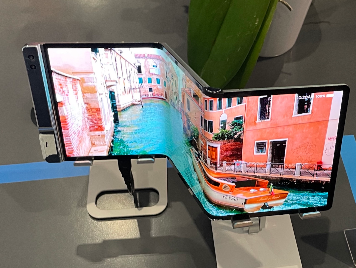
Automotive OLED utilizes flexible substrates to bond with curved dashboards, meeting automotive-grade temperature resistance standards of -40°C to 105°C. HUDs employ Transparent OLED (transmittance...
댓글 남기기
이 사이트는 hCaptcha에 의해 보호되며, hCaptcha의 개인 정보 보호 정책 과 서비스 약관 이 적용됩니다.