

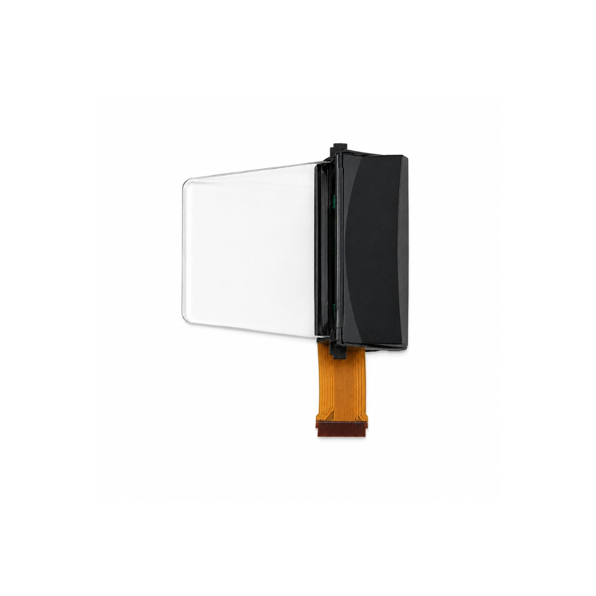
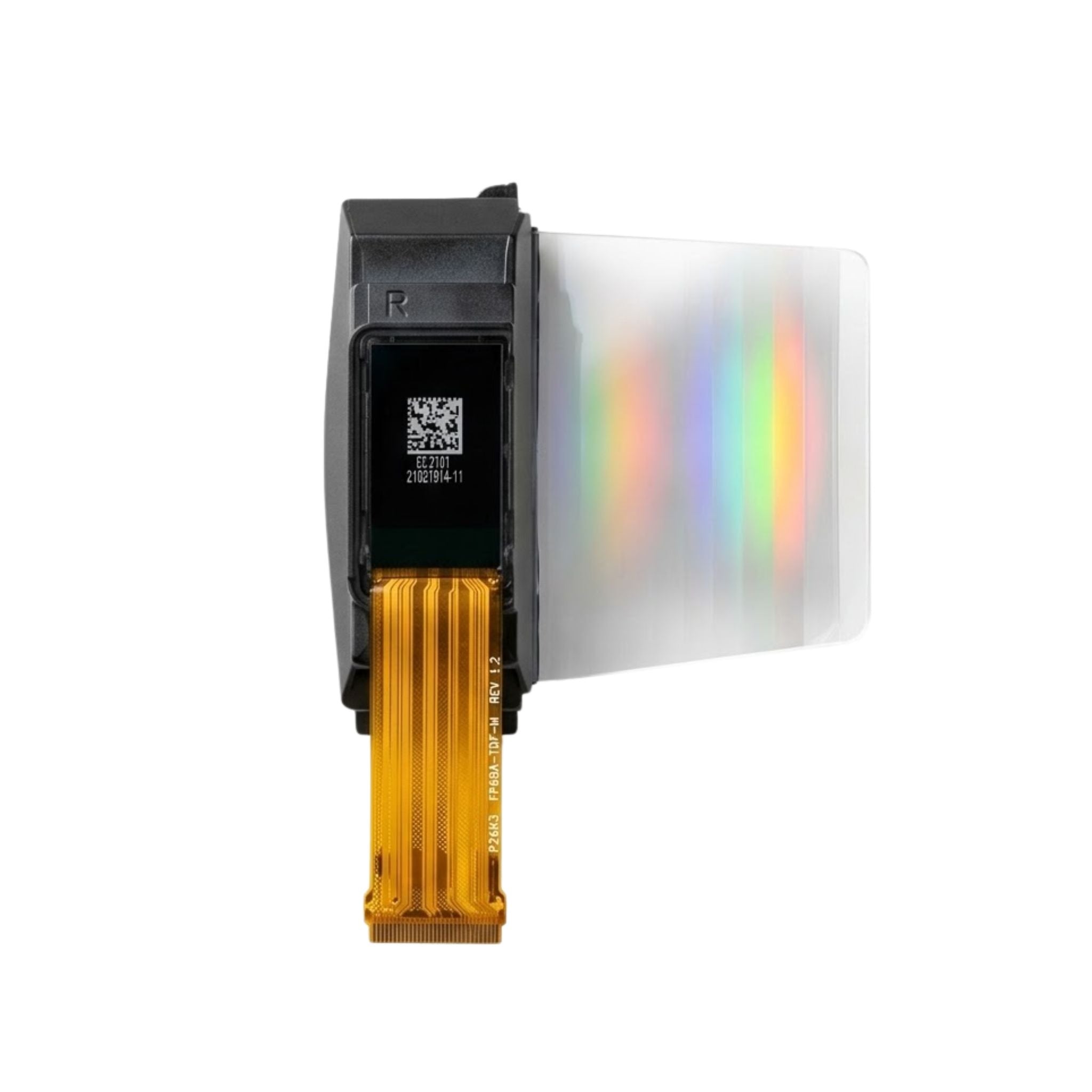


What is a cog LCD
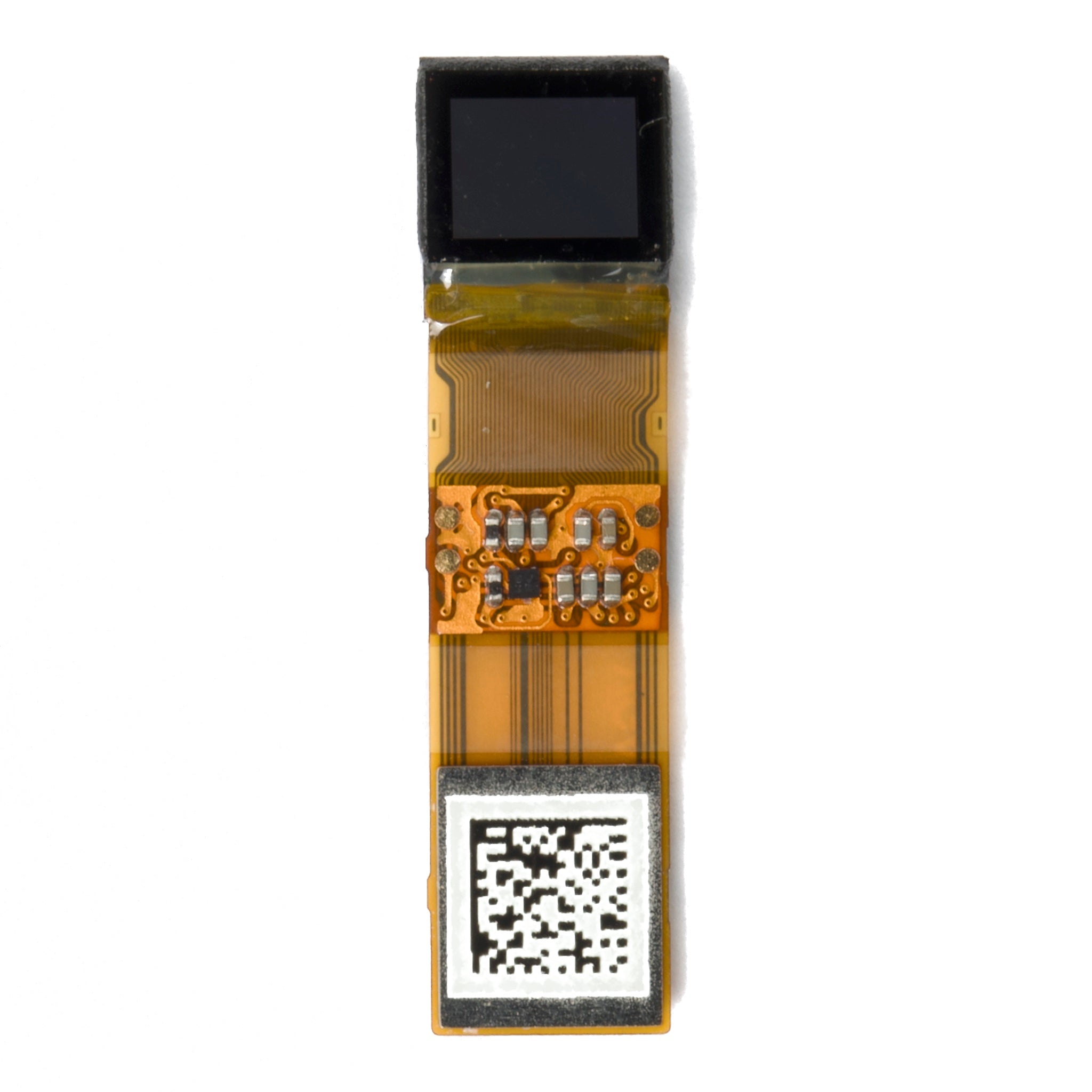
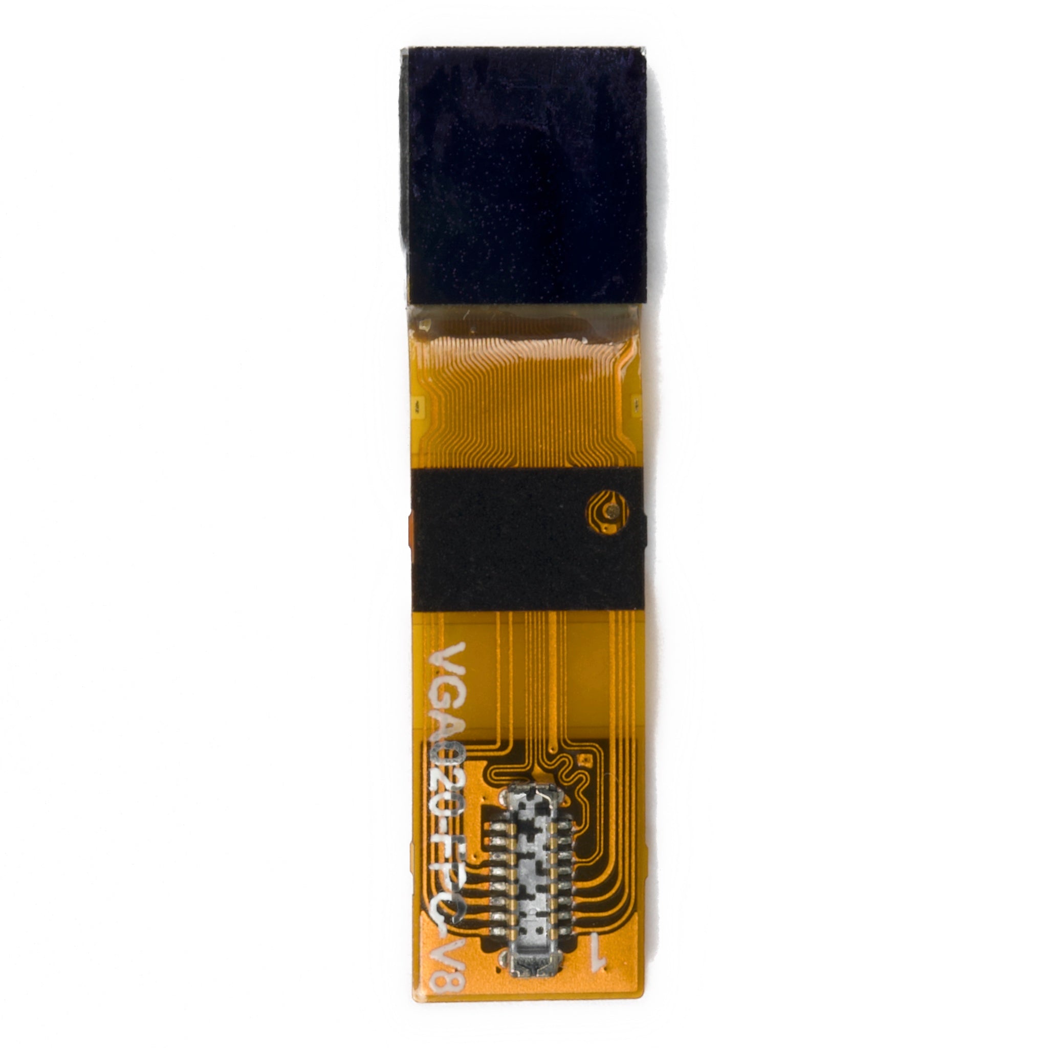
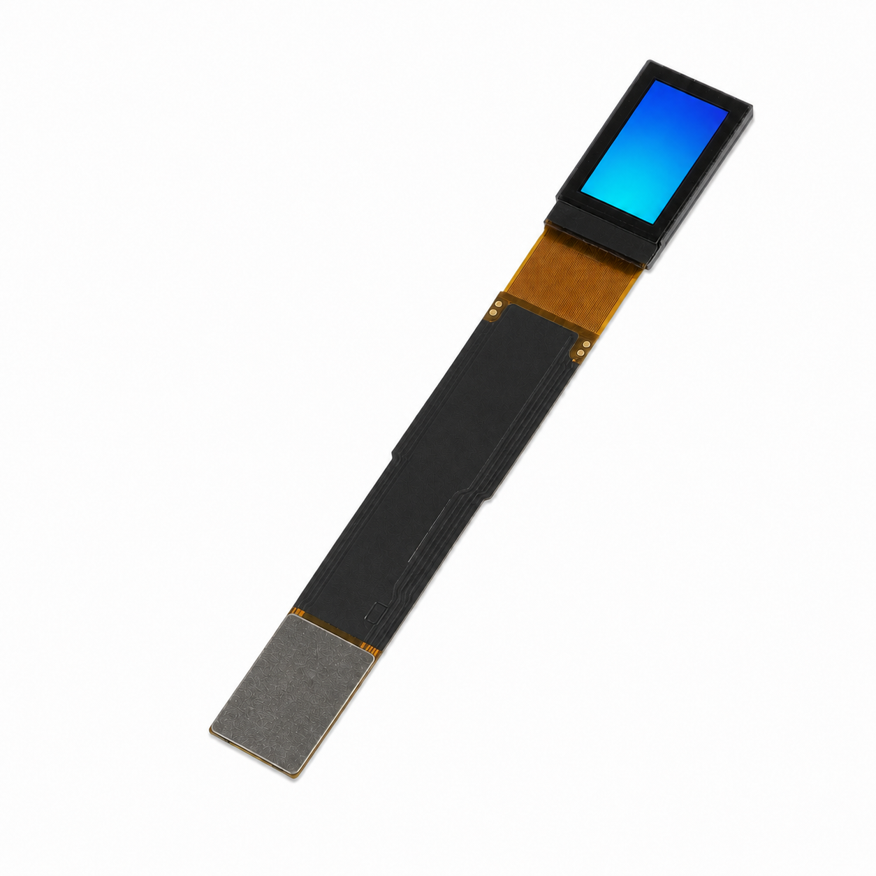
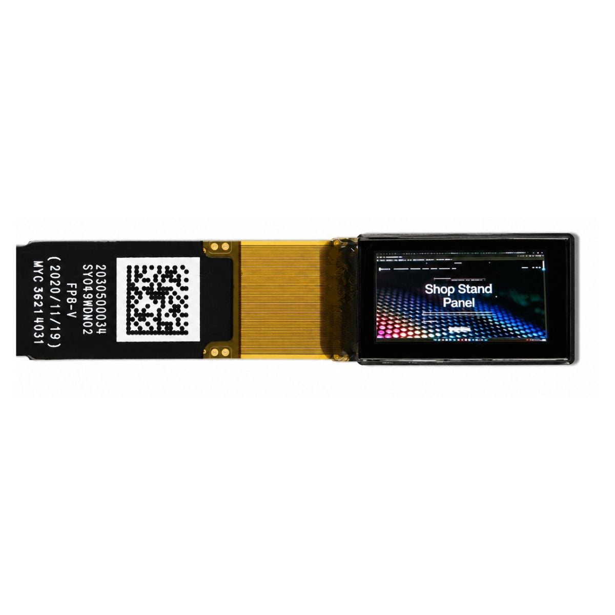
A COG (chip-on-glass) LCD is a liquid crystal display whose driver IC is mounted as a bare die directly onto the glass substrate, rather than packaged in a plastic or ceramic carrier and soldered to a circuit board. The bond replaces a connector, a PCB and a package with a small area of anisotropic conductive film, which is why COG modules are thin, compact and inexpensive in volume.
What the bond actually is
The die sits face down on the glass, aligned so its bumps meet the ITO traces patterned on the substrate. An anisotropic conductive film — an adhesive loaded with conductive particles — is pressed and cured between them. The particles conduct vertically where the bumps press them, and stay insulating laterally, so hundreds of connections can be made at once across a fraction of a millimetre.
That is the whole mechanism. There is no solder joint, no socket and no package lead to inspect. The connection quality depends on alignment accuracy, bonding pressure, temperature profile and the cleanliness of the surfaces — which is why the process lives inside the module factory rather than in the assembly house.
Why it makes modules thinner and cheaper
Three savings come directly from removing the package. The IC no longer needs a plastic body, so the stack shrinks by roughly the package height. The connection no longer needs a PCB area for the driver, a connector and its keep-out zone, so the module footprint shrinks too. And the assembly steps for soldering and inspecting a fine-pitch package disappear from the production line.
The fourth saving is less obvious and often larger in fine-pitch designs: contact density. Because the bond pads can be pitched more tightly than a connector's contacts, COG can drive more segments or a larger matrix without adding interconnect hardware. In small graphic LCDs, that density is what keeps the module compact as resolution rises.
How COG differs from COF and TCP
Three bonding routes exist for connecting a driver to a display, and they sit on a spectrum of flexibility. COG bonds the die directly to the glass, which is the shortest and cheapest electrical path but cannot bend. COF (chip-on-film) bonds the die to a flexible film, which allows the driver to sit behind the display or wrap around an edge, at a higher cost. TCP (tape carrier package) mounts a packaged die on a film with a lead frame, historically common in larger panels and now largely superseded by COF in small modules.
The choice follows from the mechanical design. If the driver can live on the glass within the bezel, COG is the cheapest answer. If the bezel must be narrow, or the driver has to sit on the back of the module, COF pays for itself by removing the bezel width constraint.
What the bonding process demands
Anisotropic conductive film bonding is a three-variable process: alignment accuracy, bonding pressure and temperature profile. Alignment determines whether the bumps land within a few micrometres of the ITO pads; pressure and temperature determine how well the conductive particles compress and how completely the adhesive cures.
Two failure signatures follow from getting it wrong. Insufficient pressure or heat produces a high-resistance bond that passes at room temperature and fails after thermal cycling. Excess pressure cracks the die or the glass. Neither is visible without inspection, which is why bond pull tests and cross-sections belong in the qualification data rather than in the final inspection only.
What it costs in repairability
A COG bond is effectively permanent. If the driver fails, the die cannot be swapped: the assembly is either reworked with dedicated equipment or scrapped. For a low-cost module in a disposable consumer product that trade is rational; for a field-serviceable industrial instrument it has to be weighed against the cost of a replacement module.
The bond also sets a floor on mechanical care during integration. Flexing the glass near the bond area, or stressing the FPC where it meets the substrate, can crack the bond or the ITO traces. The mechanical drawing should state the keep-out zone and the minimum bend radius for exactly this reason.
Where COG fits
The format suits small character and graphic LCDs — instrument readouts, meter displays, portable devices, control panels with limited area. It suits high-volume production where the per-unit saving compounds, and it suits designs where the module thickness is a mechanical constraint rather than a preference.
It fits less well where the driver must be replaceable, where the environment stresses the glass repeatedly, or where volumes are too low for the bonding set-up to amortise. In those cases a COB (chip-on-board) or a packaged driver on a flex tail is usually the better engineering answer.
What to specify
- Bond type and die supplier, since second-sourcing a bonded assembly is not a drop-in substitution.
- ITO trace geometry and the keep-out zone around the bond.
- FPC attachment method — hot-bar or ACF — and its flexing endurance.
- Operating temperature range, because the bond's mechanical properties change at the extremes.
- Luminance contrast and uniformity with their measurement basis, standardised in ISO 9241-307[1].
COG modules in character and graphic formats are listed in the COG LCD collection; the wider families are grouped under character LCD and graphic LCD displays.

A COG LCD mounts its driver chip directly on the glass, trading repairability for thinness, contact density and cost at volume. It is the right structure for compact character and graphic displays in high-volume products, and the wrong one where the driver must be serviceable.
References
- ISO 9241-307:2008 — Ergonomics of human-system interaction — Part 307: Analysis and compliance test methods for electronic visual displays. International Organization for Standardization. https://www.iso.org/standard/40102.html
더 읽기
TFT screens generally offer solid everyday durability, with most models withstanding around 1,000 hours of continuous use without noticeable fading and.
The primary difference lies in their applications and manufacturing processes: SMD (Surface-Mount Device) refers to tiny electronic components (e.g., 0402.
댓글 남기기
이 사이트는 hCaptcha에 의해 보호되며, hCaptcha의 개인 정보 보호 정책 과 서비스 약관 이 적용됩니다.