



What is a TFT LCD screen
A TFT LCD screen is a liquid crystal display in which every pixel has its own thin-film transistor switch, deposited on the glass as part of the array. The switch lets the driver address pixels one row at a time while each pixel holds its charge until the next frame. That single change is what turned liquid crystal from a calculator display into a screen that can show video.
Why the transistor is there
In a passive matrix, each row is driven in turn and the liquid crystal must hold its state while the other rows are addressed. As row count rises, the time each pixel is driven shrinks, contrast falls and neighbouring pixels start to crosstalk. Adding a transistor at every intersection decouples the pixel from the scan: the pixel charges through its switch and then sits isolated behind a closed gate.
The charge is held by the pixel capacitance together with a storage capacitor formed alongside the row line. It is the capacitor that maintains the voltage between refreshes, not the liquid crystal molecules, which respond to the field rather than store charge. Leakage through the switch and the liquid crystal slowly drains the capacitor, so the frame rate and the storage capacitance are chosen to keep the voltage within tolerance for a whole frame.
The layer stack
A module is a stack, and every layer has a cost and an optical consequence.
- Backlight: edge-lit or direct-lit LEDs, with a light guide, diffuser and brightness-enhancement films to spread and recycle the light.
- Rear polariser: passes one polarisation state into the cell.
- TFT glass: the array of transistors, row and column lines, pixel electrodes and storage capacitors.
- Liquid crystal layer: a few micrometres thick, held by spacers, with alignment layers that set the resting orientation.
- Colour filter glass: red, green and blue filters in stripes, plus a black matrix between them and usually the common electrode or the in-plane electrode pair depending on the mode.
- Front polariser, then touch sensor and cover window if the module includes them.
The two polarisers are crossed at rest, so a pixel that lets the liquid crystal twist the light passes it and a pixel that does not blocks it. The liquid crystal does not emit or absorb light; it steers polarisation, and the polarisers do the blocking. A pixel that is switched off still leaks a small amount between imperfectly crossed polarisers, which is the physical origin of the native contrast limit.

How a frame is written
The gate driver selects one row, turning on every transistor along it. The source driver then places a voltage on each column, and the capacitor at each intersection charges to that voltage. The gate closes, the row holds, and the next row is selected. A full frame is written row by row at the frame rate, and the liquid crystal responds to the voltage it was given, changing the amount of light the pixel passes.
Because the display is written sequentially rather than all at once, tearing appears if the frame buffer changes mid-scan; that is a timing problem in the host and the interface, not a defect of the panel. The transistor array itself is built in a sequence of deposition and photolithography steps, and the number of steps is one of the reasons yield, and therefore price, moves with resolution.[2]
Liquid crystal modes
The array is only half the design. The electrode layout and the liquid crystal orientation decide how the pixel behaves off axis and how fast it switches.
Twisted nematic is the oldest and cheapest mode, with narrow viewing angles and a characteristic off-axis greyscale shift. In-plane switching places both electrodes on one substrate and rotates molecules within the plane, which holds colour and contrast much further off centre at the cost of transmission. Vertically aligned modes give higher native contrast because the relaxed state blocks light more completely, with their own trade-offs in response and off-axis gamma.
Within each family the details vary by generation and supplier, so two panels described by the same mode name can behave differently. The mode name is a starting point, not a specification.
The backlight and what it does to contrast
An LCD cannot be darker than the light that leaks through its off state, and no amount of backlight engineering changes that ratio. Raising the backlight lifts white and black together, so it improves visibility in a bright room without improving native contrast. This is the distinction that marketing material usually blurs.
Local dimming, including mini-LED backlights with many independently controlled zones, raises the dynamic contrast of a scene by turning down the light behind dark areas. The panel's native contrast is unchanged; the improvement appears only where the content and the zone layout allow it, and it brings haloing around bright objects on dark backgrounds. Both numbers belong in a specification, clearly labelled.
Colour and gamut
Colour comes from the filters, and the achievable gamut depends on the spectrum of the backlight as much as on the filters. A blue LED with a yellow phosphor gives a modest gamut; narrow-band red and green sources, whether phosphor-converted or quantum dots, widen it. Filter thickness and pigment loading trade gamut against transmission, so a wide-gamut panel usually needs a brighter backlight for the same on-screen luminance.
Coverage and volume are different claims. Coverage says how much of a colour space the panel reaches; volume says how far it exceeds it in every direction. A panel can report high coverage and still look oversaturated, so ask which figure is quoted and against which white point.
Specifications and the conditions behind them
Numbers without conditions cannot be compared. Luminance should be quoted for a full-white field after warm-up at a stated drive setting. Contrast should say whether it is native or dynamic, and at what luminance. Viewing angle should name the contrast ratio used as the limit, since the familiar angle ratings are defined at a low ratio rather than at the point where the image fails. Response should name the grey levels, the temperature and the measurement threshold. Uniformity should name the number and position of measurement points. ISO 9241-307 sets out how these measurements are made and reported, and it also defines how defective pixels are classified and counted, which is what a panel grade should reference.[1]
Where TFT LCD still wins
Sunlight readability is the clearest case: a backlit LCD can be pushed to high sustained output across the whole screen, which an emissive panel finds harder without ageing faster. Service life is another, since the backlight and the array age slowly and there is no burn-in pattern to accumulate. Supply is mature across a wide range of sizes and resolutions, and the price per unit at large diagonals remains hard to match. For instrument panels that show the same layout for years, those properties matter more than black level.
Where it gives ground
Native contrast is limited by light leakage, response slows at low temperature unless the liquid crystal mixture and the drive are chosen for it, and the backlight consumes power continuously even for a dark image. Thin, curved and foldable designs are possible but constrained by the glass and the cell gap. None of these is fatal; each is a design constraint to be declared early.
Specifying a module
Write down the diagonal and resolution, the mode, the luminance with its measurement condition, native and dynamic contrast separately, the interface with clock rate, colour depth and frame rate stated together, the operating temperature, the touch and window construction, the defect class and the lifetime target. Then compare suppliers on those lines. The TFT display modules range covers the general case, IPS display modules the wide-angle requirement, and industrial displays the wide-temperature and long-life cases.
Summing up
A TFT LCD screen is a light valve with a switch at every pixel. The transistor array makes video possible, the liquid crystal and polarisers set the contrast limit, and the backlight sets the brightness. Understand those three roles separately and most of the specification language stops being confusing.
References
- ISO 9241-307:2008 — Ergonomics of human-system interaction — Part 307: Analysis and compliance test methods for electronic visual displays. International Organization for Standardization. https://www.iso.org/standard/40102.html
- Hilsum, C. (2010). Flat-panel electronic displays: a triumph of physics, chemistry and engineering. Philosophical Transactions of the Royal Society A, 368(1914), 1027–1082. https://doi.org/10.1098/rsta.2009.0247
더 읽기
When comparing MicroLED and AMOLED, MicroLED typically offers higher peak brightness (around 2000 nits) versus AMOLED's 1000–1500 nits, while both deliver.
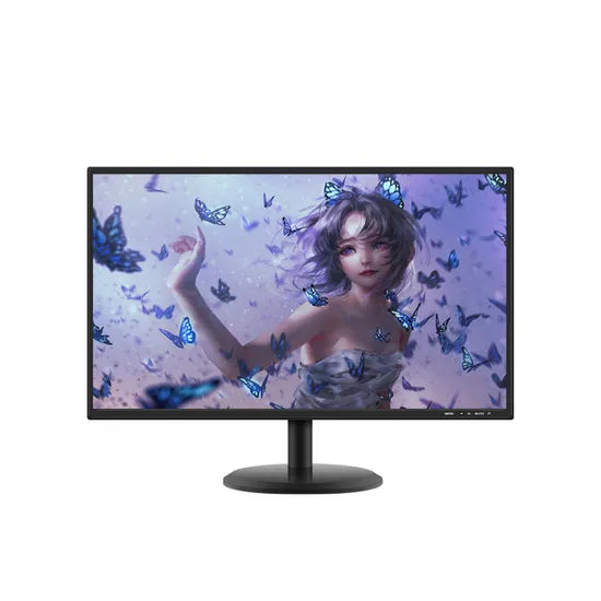
TFT (Thin-Film Transistor) is primarily used in liquid crystal displays (LCDs) to enhance picture quality, powering devices like smartphones and tablets.
댓글 남기기
이 사이트는 hCaptcha에 의해 보호되며, hCaptcha의 개인 정보 보호 정책 과 서비스 약관 이 적용됩니다.