









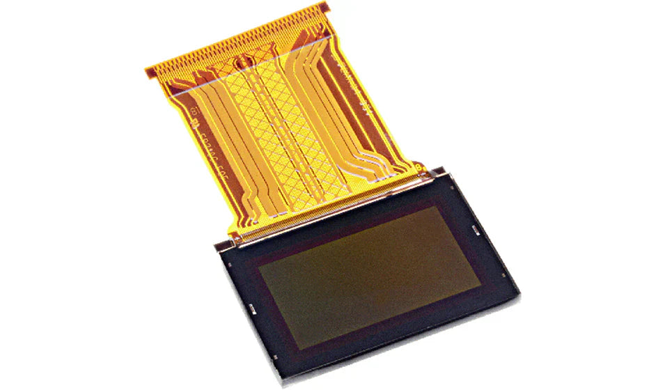
What Is The Resolution Of Micro OLED Modules
Micro OLED modules span roughly 640×480 to 4K-class panels, with 1024×768, 1280×1024 and 1920×1080 the most common catalog formats and near-square layouts such as 2048×2048 used in binocular AR designs. Raw pixel count says little on its own: what decides perceived sharpness is pixel density measured against the field of view the optics deliver.
Resolution families
Micro OLED is built on a silicon backplane, so the panel is a die cut from a wafer and can be sized to the customer's optical design rather than to a glass mother sheet. That freedom still lands on a few familiar families. VGA-class parts (640×480) cover simple monocular viewers and sighting optics. XGA-class parts (1024×768) dominate 0.3–0.5 inch augmented-reality engines. 1080p-class parts (1920×1080) serve 0.5–0.8 inch head-mounted displays and electronic viewfinders. Above that, suppliers list 2K and 4K-class panels, frequently in square formats.
Square formats are a design decision, not a marketing one. A rotationally symmetric eyepiece projects a circular image, so a square panel uses the available field more fully than a 16:9 rectangle, which leaves the top and bottom of that circle empty. Rectangular panels remain the better fit when the content is video and the optics are anamorphic.
The backplane sets how uniformly and how quickly each pixel can be addressed, which is why two panels with identical resolution can behave quite differently in the same optic[2].
Pixels per degree
Near-eye displays are better specified in pixels per degree than in pixels per inch. Divide horizontal resolution by the horizontal field of view the eyepiece provides: a 1920-pixel panel across a 40-degree horizontal field yields 48 pixels per degree.
Human acuity is commonly taken as about one arcminute, equivalent to roughly 60 pixels per degree. Panels below that threshold show structure on high-contrast edges; panels above it spend silicon and power on detail the eye cannot resolve through that particular optic. The threshold moves with eye relief, pupil position and the content's contrast, so treat it as a design target rather than a pass mark.
Calculating PPI
Datasheets quote diagonal and resolution, and density follows from the two: PPI = √(W² + H²) ÷ diagonal, with W and H in pixels and the diagonal in inches. A 0.39-inch 1024×768 panel works out to 1280 ÷ 0.39, about 3,280 PPI. A 0.71-inch 1920×1080 panel gives 2203 ÷ 0.71, about 3,100 PPI. A 1.3-inch 2560×2560 panel gives 3620 ÷ 1.3, about 2,780 PPI.
Those are arithmetic results, not measurements, and they explain a counterintuitive point: the smallest panel is not automatically the densest. A larger die with a much higher pixel count can beat a small die with a modest one, so the ratio has to be computed rather than assumed from the diagonal column.

Optical limits
An eyepiece has a finite modulation transfer function. Detail finer than the optic can pass arrives as blur, so a panel that out-resolves its lens buys nothing but power and cost. The usual approach is to match pixel pitch at the image plane to the optic's cutoff, then spend the remaining budget on contrast and uniformity instead of on more pixels.
Fill factor matters as much as pitch. The non-emitting gap between pixels reads as a faint mesh, the screen-door effect, and it becomes noticeable before individual pixels do. Suppliers publish fill factor less often than resolution, so it is worth requesting directly along with a sample to inspect.
Interface limits
Resolution has to be carried by a link. For MIPI DSI, the required bit rate is roughly horizontal pixels × vertical pixels × bits per pixel × refresh rate, plus blanking overhead of perhaps a tenth. A 1920×1080 panel at 24 bits per pixel and 90 frames per second therefore needs about 5.2 Gbit/s in total, which is why these modules use multi-lane DSI rather than a two-wire bus.
That is a link budget, not proof that a given bridge chip will sustain it. Lane count, clock mode, host DMA throughput and the driver's own overhead all enter the answer, and a panel that works on a development board can still stutter on a lower-clocked production processor.
Format choices by application
Augmented-reality glasses usually run one panel per eye behind a waveguide or a birdbath combiner, and the field is deliberately narrow — a few tens of degrees — because the image has to overlay the real world without dominating it. In that setting a 1024×768 or 1280×1024 panel already produces a dense image, and the engineering effort goes into brightness and see-through uniformity rather than into more pixels.
Immersive headsets invert the priorities. They want a wide field, often past 90 degrees diagonally, which multiplies the pixel count needed to hold the same angular density. That is why headset panels climb toward 2K and 4K-class formats while the AR parts stay near XGA, and why the two product categories rarely share a display.
What datasheets omit
Uniformity, burn-in behaviour and lifetime definitions rarely appear in the headline block. OLED lifetime is normally quoted as the time to a stated fraction of initial luminance at a stated drive level, and the figure moves with content, brightness and temperature. Ask for the test condition beside the number, otherwise the comparison across suppliers is meaningless.
Gamma and the power-up sequence belong in the same conversation. A panel that needs a vendor-specific initialization table will not light correctly from a generic driver, and that table is not consistently included in public documentation. Requesting it before the design freeze avoids a late surprise at the prototype stage.
Specifying a module
- State active area and diagonal separately; the two are not interchangeable when comparing parts.
- Give resolution, pixel pitch and colour depth, and confirm the format is native rather than scaled.
- Quote brightness at a defined drive condition and contrast at a defined measurement geometry[1].
- Name the interface, lane count and expected frame rate, and ask for the link budget in writing.
- Request lifetime at a stated luminance plus the initialization sequence.
Buyers comparing micro OLED modules across suppliers will find the same resolution offered at several diagonals. The density calculation above is the fastest way to see which part actually suits the optic, and the AR and VR display range shows how formats map to headset and viewer designs.
References
- ISO 9241-307:2008 — Ergonomics of human-system interaction — Part 307: Analysis and compliance test methods for electronic visual displays. International Organization for Standardization. https://www.iso.org/standard/40102.html
- Hilsum, C. (2010). Flat-panel electronic displays: a triumph of physics, chemistry and engineering. Philosophical Transactions of the Royal Society A, 368(1914), 1027–1082. https://doi.org/10.1098/rsta.2009.0247
Resolution is the easiest part of a micro OLED specification to quote and the least informative on its own. Compute density from the diagonal, check it against the optic, and confirm the interface can carry the frame. Everything else is detail the datasheet will only give if you ask.
더 읽기
Yes, most NexPCB display modules, like their 1.3-inch I2C OLED (model NEX1301), are compatible with Arduino —they use standard I2C/SPI interfaces, with.
AMOLED display modules generally last 50,000 to 100,000 hours before brightness halves (half-life), equating to ~5-10 years with 5-10 daily hours; yet.
댓글 남기기
이 사이트는 hCaptcha에 의해 보호되며, hCaptcha의 개인 정보 보호 정책 과 서비스 약관 이 적용됩니다.