








128x64 COG LCD Graphic Display 3.18" - SPI
- 💹 Enjoy a 20% discount for orders over 500
- 📉 A 15% discount is available for orders ranging from 200 to 499
- 🎁 A 10% discount is available for orders ranging from 50 to 199
- 🎁 A 5% discount is available when ordering 10-49
Interested in customizing this product? Get in touch with us.
Order samples, immediate delivery.
Factory bulk lead time: 3 weeks.
128x64 COG LCD Graphic Display 3.18" - SPI
- 💹 Enjoy a 20% discount for orders over 500
- 📉 A 15% discount is available for orders ranging from 200 to 499
- 🎁 A 10% discount is available for orders ranging from 50 to 199
- 🎁 A 5% discount is available when ordering 10-49
Resources & Downloads
128×64 COG LCD Graphic Display 3.18" with 4-SPI Interface
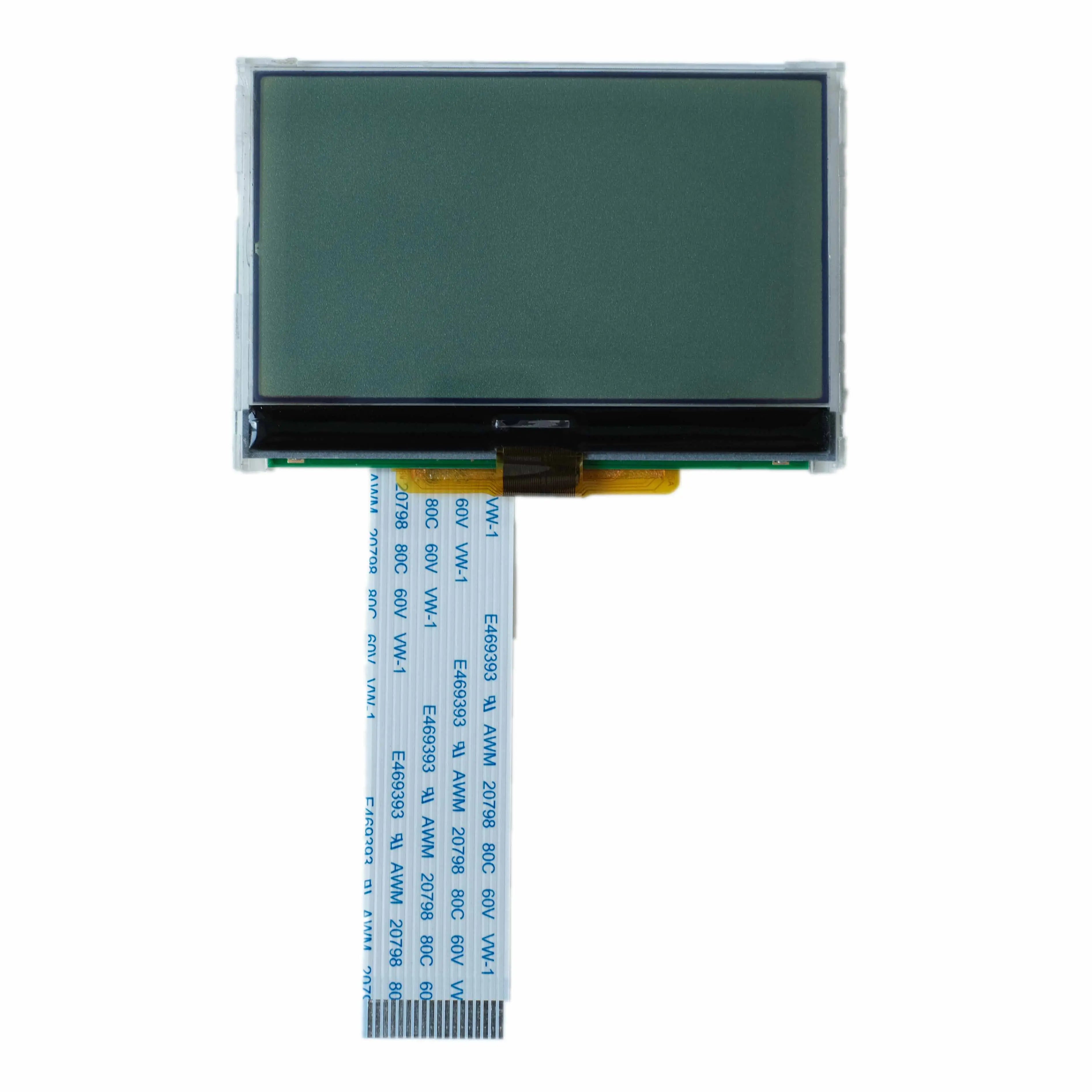
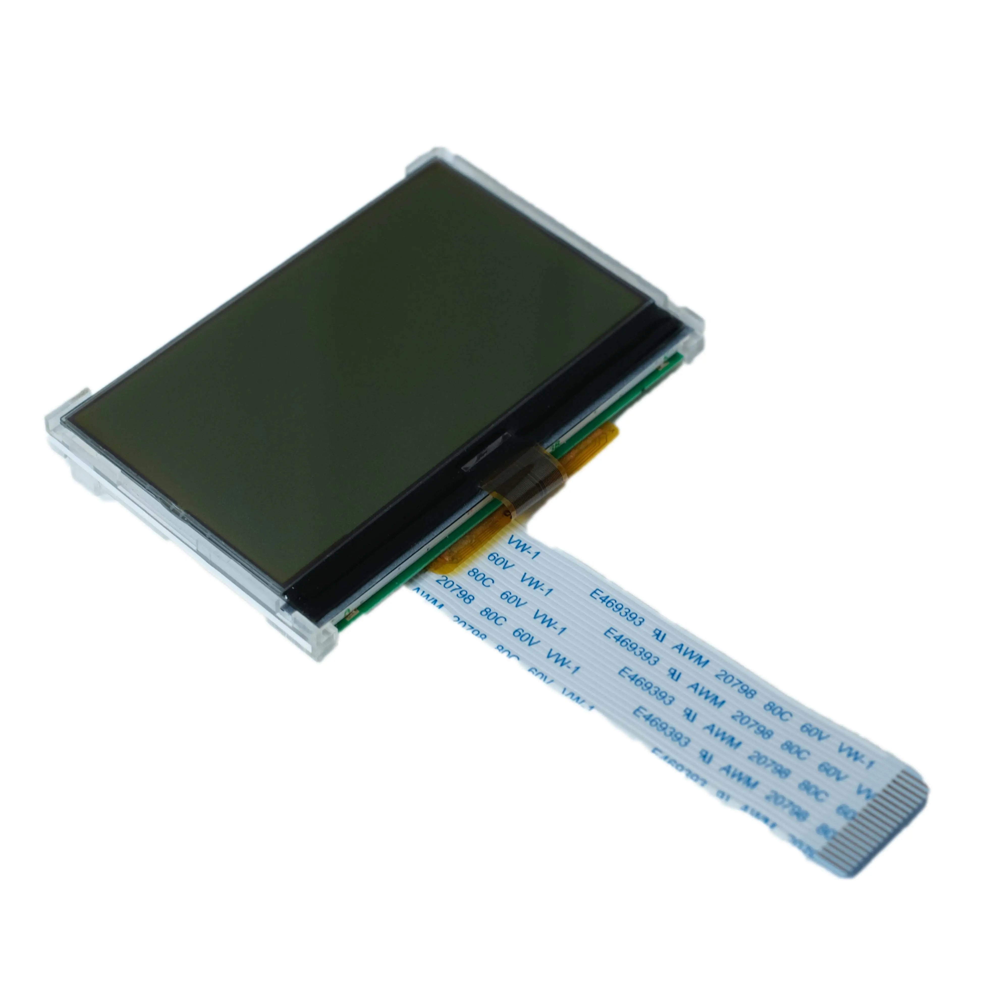
DM-COG12864-705 is a 128×64-dot FSTN transflective positive graphic LCD module with a 6:00 viewing direction, edge white LED backlight, 4-SPI host interface, and built-in ST7565 controller.
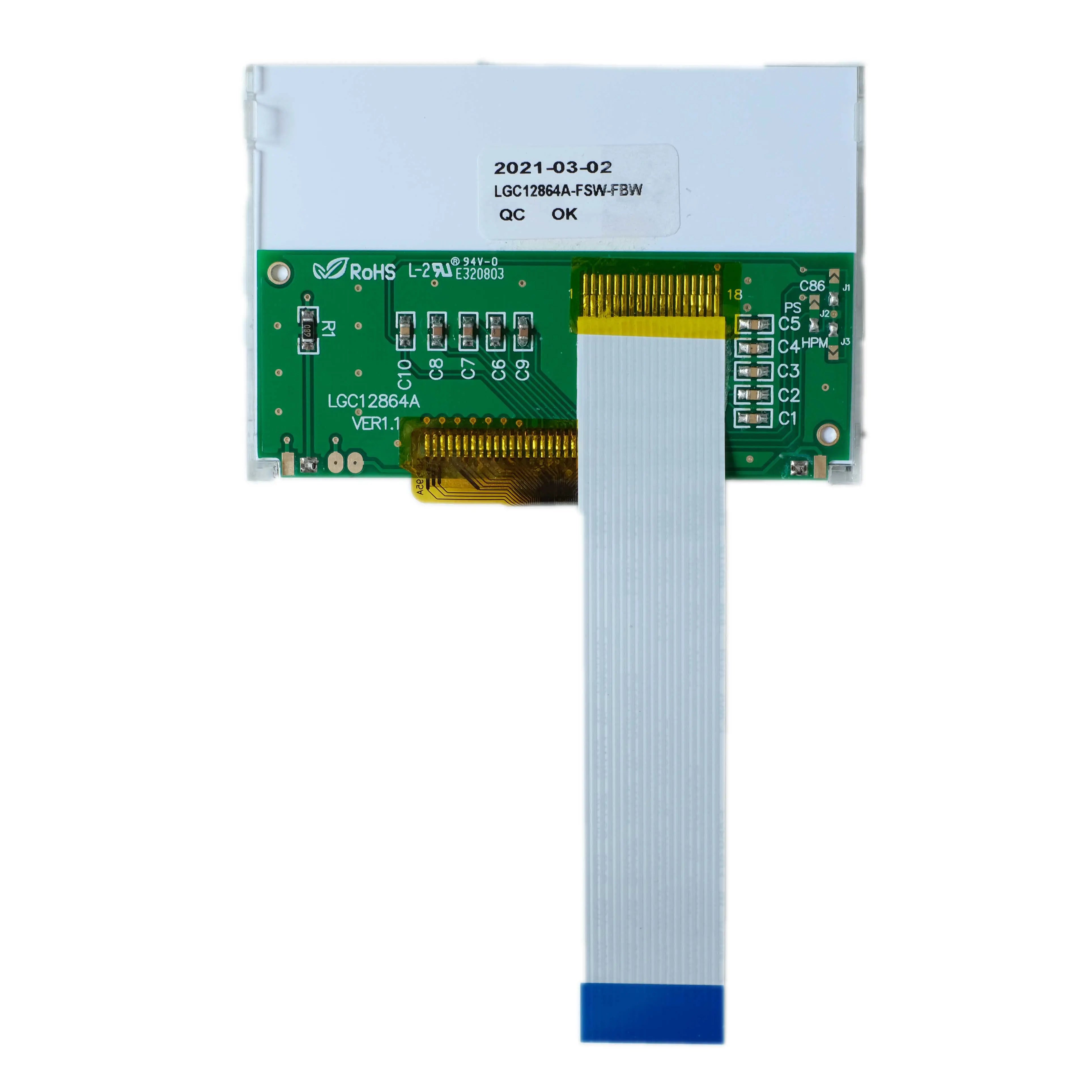
Its bottom 18-pin, 1.0 mm-pitch FPC carries the serial interface, control signals, LCD logic power, and LED backlight connections. Module-level limits on this page follow the DM-COG12864-705 datasheet.

Verified Technical Specifications
The module combines a 128×64 FSTN transflective positive LCD, ST7565 controller, 4-SPI interface, and edge white LED backlight. The table below lists the published module-level specifications.
| Parameter | Datasheet Specification |
|---|---|
| Product Model | DM-COG12864-705 |
| Resolution | 128×64 pixels |
| LCD Type | FSTN, transflective, positive |
| Viewing Direction | 6:00 |
| Controller IC | ST7565 |
| Host Interface | 4-SPI |
| Drive Method | 1/65 duty, 1/9 bias |
| Backlight | Edge white LED |
| LCD Logic Supply | 2.4 V minimum to 3.3 V maximum |
| LCD Supply Current | 147 µA maximum at Ta = 25°C and VDD = 3.3 V; backlight current is specified separately |
| Operating Temperature | -20°C to +70°C, based on the Electrical Characteristics table; confirm any higher-temperature requirement before ordering |
| Storage Temperature | -30°C to +85°C, absolute maximum |
| Module Weight | 31.2 g |
| Touch Function | No touch-panel or touch-controller specification is provided in the supplied module datasheet |
Mechanical Dimensions and FPC Layout
The module outline is 80.0 ± 0.5 × 54.0 ± 0.5 mm, with a 70.7 × 38.8 mm viewing area and a bottom 18-pin FPC. Use the drawing to define the bezel opening, display position, FPC route, and connector clearance.
FPC Connection
Pin count: 18 pins
Pitch: 1.0 mm, shown as P1.0×17 = 17 mm
Tail width: 18 mm at the contact end
Viewing direction: Indicated toward 6:00 in the drawing
The mating-connector part number is not identified in the supplied module datasheet. Confirm connector compatibility and insertion orientation before PCB release.
Electrical and Optical Characteristics
The LCD logic circuit operates from 2.4 V to 3.3 V, while the edge white LED backlight is specified separately. The datasheet lists a typical forward voltage of 4.2 V and a typical forward current of 80 mA for the backlight.
Logic Levels
VIL is 0 to 0.6 V. VIH is 2.2 V to VDD. VOL is 0.4 V maximum, and VOH is 2.4 V minimum.
White LED Backlight
The white LED backlight is specified at 4.2 V typical forward voltage and 80 mA typical forward current. Select the backlight driver according to these ratings and verify brightness in the final application.
Viewing Angles
Vertical viewing-angle limits are -60° and +35°. Horizontal viewing-angle limits are -40° and +40°.
Response Time
Tr + Tf is specified as 300 µs typical and 500 µs maximum at 25°C.
Contrast Ratio
The optical table specifies a typical contrast ratio of 6 under the datasheet measurement conditions.
Luminance
No luminance value is entered in the supplied module datasheet. Confirm the required backlight brightness and measurement condition before ordering.
18-Pin Interface Assignment
The bottom 18-pin FPC provides VSS and VDD, controller reset, chip select, A0 register select, serial clock, serial data, and LED backlight connections. Pins 7 through 14 are assigned to VDD in the module pin table.
Datasheet Reliability Conditions
The module datasheet lists 200-hour high- and low-temperature storage and operation tests, together with humidity, thermal-shock, vibration, and static-electricity conditions. These are published qualification conditions, not lifetime or regulatory certifications.
Engineering Review Before Integration
Before freezing the PCB and enclosure, verify the document revision, FPC orientation, backlight driver, reset timing, contrast setting, and visual performance with a production-intent sample.
Separate Logic and Backlight Design
Do not treat the 2.4-3.3 V LCD logic rail and the LED-backlight supply as the same load. Size the backlight driver and current control from verified sample measurements.
Host I/O Voltage
The module input-high threshold is 2.2 V and the logic supply maximum is 3.3 V. A host using higher I/O voltage requires an appropriate interface review and may require level translation.
FPC and Mechanical Fit
Check contact orientation, 18-pin pitch, tail position, bend clearance, bezel opening, and connector height against the drawing and a physical sample.
Initialization and Command Set
Use the module command table and the ST7565 manual to establish reset timing, display bias, electronic volume, addressing, display direction, and display-on sequence. Do not apply the generic controller IC supply limits to the completed module.
Touch Configuration
No touch-panel, touch-controller, or touch-interface data is specified for this module. Confirm any project-specific touch requirement separately before ordering.
Document and Sample Verification
Confirm the current revision, production configuration, backlight behavior, connector match, contrast setting, and visual performance using an approved sample before volume production.
Common Questions
The answers below separate published module data from items that require confirmation before ordering.
Does the module include touch?
No touch specification is provided in the supplied module datasheet. Confirm any touch-panel requirement separately.
What is the correct storage-temperature range?
The electrical-characteristics table specifies -30°C to +85°C as the absolute-maximum storage range.
Is 147 µA a typical current?
No. The module datasheet places 147 µA in the maximum column at Ta = 25°C and VDD = 3.3 V. It does not include the separately specified LED-backlight current.
Is the backlight powered directly from the LCD logic rail?
The datasheet lists the LCD logic rail and LED-backlight characteristics separately. Review and verify the backlight driver instead of assuming direct connection to the logic supply.
Is a luminance value available?
The luminance row in the supplied optical table contains no numerical value. Confirm brightness requirements and test conditions before ordering.
Which voltage limits should be used if the ST7565 manual differs from the module datasheet?
Use the DM-COG12864-705 module datasheet for the completed module. The ST7565 document describes the generic controller IC and is used here for command and functional reference.
Download Official Engineering Documents
Download the module datasheet for DM-COG12864-705 dimensions, pin assignment, electrical limits, optical data, timing, commands, and reliability conditions. Use the ST7565 manual for controller functions and command definitions; where the documents differ, the module datasheet takes precedence for this product.