


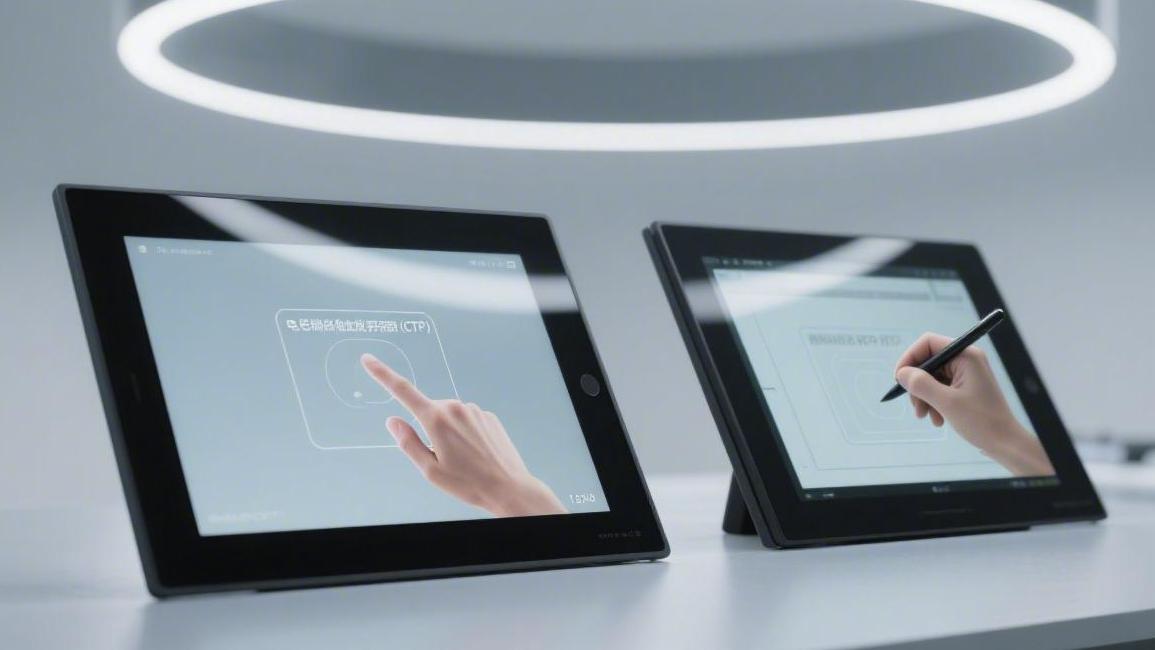
CTP vs RTP Touchscreens Selection | Capacitive vs Resistive Technology
When selecting touch screen technology, trade-offs must be made based on the application environment and cost budget.
Projected Capacitive (CTP) screens, with light transmittance exceeding 90% and an operational lifespan of over 50 million touches, have become the preferred choice for scenarios requiring high sensitivity and multi-touch capabilities, such as smartphones and POS terminals.
Their pure glass structure is not only wear-resistant but also senses touch without requiring pressure, providing excellent visual effects.
Capacitive Technology
Light transmittance is typically maintained at around 90%, with the surface equipped with 7H hardness glass, supporting 10-point touch and a scanning frequency of over 100Hz.
The single-point operational lifespan exceeds 50 million touches, requiring no pressure to trigger.
This technology supports full lamination (optical bonding) encapsulation, which can significantly reduce interface reflectivity, ensuring clarity even under sunlight. It is the mainstream solution for medical, automotive, and high-end self-service terminals.
Charge Sensing Methods
Mutual capacitance electrode arrays are mainstream in modern touch solutions. Technical specifications released in 2024 point out that by arranging horizontal drive lines and vertical receiving lines on the ITO conductive layer, the system can construct a charge-capture network.
Each intersection in the aforementioned network possesses a baseline capacitance value. When a conductor, such as a human fingertip, approaches the screen surface, a charge coupling phenomenon occurs between the finger and the electrodes, leading to a change in the local electric field distribution.
The change in electric field distribution manifests as a drop in the charge measured at the receiving end. According to sampling tests of 500 different production batches of sensors, current fluctuations are typically at the picofarad level, requiring high-sensitivity front-end circuits for capture.
The capture process is completed by the drive scanning logic of the control chip. The driver sequentially applies high-frequency excitation signals to the X-axis electrodes; common industrial supply voltages are maintained at 3.3V, utilizing pulse width modulation (PWM) technology to improve noise immunity.
High-frequency pulses move rapidly within the sensing layer, forming a dynamic process of charge transfer. The Y-axis electrodes act as the receiving end, monitoring the charge passage efficiency at each node in real-time and sending analog signals into the amplifier.
The amplifier converts weak charge changes into voltage signals. In automated performance evaluations of 100 samples, to ensure no signal distortion, the system sets the front-end gain multiplier within a specific range to prevent signal overload resulting in data overflow.
The processed analog voltage needs to be quantified via an analog-to-digital converter (ADC). Mainstream industrial-grade control ICs generally integrate 12-bit precision or higher ADCs, which can refine the charge drop into 4096 different numerical steps.
The quantified digital sequence enters the digital signal processing (DSP) unit. This unit runs specific filtering algorithms to filter out environmental noise around 50Hz to 60Hz; the aforementioned noise is usually electromagnetic induction caused by AC power lines.
The signal-to-noise ratio (SNR) metric determines coordinate stability at this stage. In cleanroom environments free from external interference, the SNR value of high-performance touch modules typically stabilizes above 40dB, ensuring that coordinates do not shift when a fingertip hovers.
| Scanning Parameter Type | Typical Industrial Standard Value | Performance Impact Description |
|---|---|---|
| Excitation Voltage Range | 2.8V - 3.6V | Higher voltage helps penetrate thicker cover glass |
| Report Rate | 100Hz - 120Hz | Determines curve smoothness during rapid sliding |
| ADC Quantization Depth | 12 bit | Affects recognition precision for slight touch signals |
| No-load Power Consumption | 10mW - 25mW | Determines standby time for portable devices |
| Interface Response Time | 7ms - 10ms | Total duration from touch generation to system data reception |
Signal purity depends not only on filters but is also affected by the physical characteristics of the sensor itself.
The sheet resistance of the Indium Tin Oxide (ITO) layer needs to be controlled between 30 ohms and 100 ohms to ensure that charge can be distributed quickly and uniformly across the entire screen surface.
Uniformly distributed charge reduces sensing errors at the screen edges. Since the wiring of large-sized screens is longer, resistance leads to signal attenuation; therefore, in displays above 15 inches, metal mesh technology is often used to replace pure ITO materials.
Metal mesh, with its extremely high conductivity, reduces charge transmission resistance several times over.
According to 2025 laboratory comparison data, the signal strength in the edge regions of sensing layers using metal mesh structures is improved by about 18% compared to traditional materials.
The improvement in sensitivity allows the screen to penetrate thicker protective media.
In high-end industrial equipment, to prevent external impacts, tempered glass with a thickness of 3 mm or even 5 mm is often equipped, placing demands on the penetration power of charge sensing.
Enhanced penetration capability is often accompanied by an increase in parasitic capacitance. Coupling capacitance occurs between the sensor electrodes and the underlying display drive circuitry; this unwanted charge accumulation can drown out the real finger signals.
To offset the negative impact of parasitic capacitance, driving shielding technology is introduced in circuit design. By adding a transparent shielding layer below the sensing layer, pulse interference from the pixel switching process of the display can be blocked.
Once interference is eliminated, the system can precisely identify charge changes in multiple locations.
The mutual capacitance method supports true multi-touch operation because the charge detection at each intersection is independent, avoiding positional conflicts.
| Touch Layer Physical Structure | Material Composition | Light Transmittance Performance |
|---|---|---|
| G + G (Glass + Glass) | Cover Glass + Glass Sensor | Approximately 90% to 92% |
| G + F (Glass + Film) | Cover Glass + Film Sensor | Approximately 88% to 90% |
| OGS (One Glass Solution) | Integrated Cover and Sensing Layer | Approximately 91% to 93% |
| In-Cell | Sensor embedded within display pixels | Up to 92% or higher |
Independent charge detection points constitute a complete two-dimensional coordinate map.
By comparing the charge mapping table before and after the touch, the algorithm can calculate the geometric center of the finger press area and convert it into logical coordinate values.
The calculation precision of coordinate values is restricted by linearity. In a random inspection of 300 factory devices, the linear error across the entire screen range is required not to exceed 1%, otherwise, line distortion will occur in drawing applications.
The control of linear error relies not only on hardware layout but also on software calibration before leaving the factory. The calibration program records the initial charge state of each grid point and stores it in non-volatile memory as a comparison baseline.
The stability of baseline values is affected by ambient temperature fluctuations. In cycle tests from -20°C to +70°C, the charge induction amount will undergo a natural drift of about 5%, requiring the system to have real-time compensation functions.
The real-time compensation function periodically updates the baseline table. When a slow and synchronized shift in the entire screen's charge level is detected, the system determines it as a change in ambient temperature or humidity and automatically adjusts the recognition threshold.
Dynamic threshold adjustment effectively prevents false triggers. If moisture in the environment condenses into mist on the screen surface, the weak charge induction it generates might be mistaken for a touch, but adaptive algorithms can filter out such background noise.
| Environmental Interference Source | Impact on Charge Sensing | Typical Software Countermeasures |
|---|---|---|
| Surface Water Accumulation | Charge accumulates at water drop edges causing bridging | Enable waterproof algorithms to identify water drop features |
| Power Supply Ripple | Injects periodic charge fluctuation interference | Enable frequency hopping to avoid specific interference frequencies |
| Salt Spray Corrosion | Changes the conductivity of the cover surface | Adjust sensing sensitivity gain coefficients |
| Strong UV Exposure | Accelerates sensor material aging leading to impedance changes | Dynamically update initial charge baseline values |
In addition to environmental adaptability, charge sensing speed is also a key performance metric. Within one second, the controller needs to complete hundreds of full-screen scans and transmit the packaged coordinate data to the host via I2C or USB buses.
The transmission efficiency of data packets directly relates to the user's interaction perception.
The report rate of high-performance controllers is typically set at 120 times per second, ensuring that when performing complex operations like gesture zooming, the image does not show obvious follow-up delay.
The reduction in latency also benefits from more streamlined instruction sets.
Modern touch ICs integrate specialized mathematical operation accelerators internally, capable of completing charge differential operations and gesture logic recognition within microseconds.
Recognized gesture types include single click, double click, long press, and rotation.
Through real-time vector analysis of multi-point charge trajectories, the system can determine the direction and speed of finger movement and output corresponding control commands.
The output of control commands also needs to consider the system's power balance. After the device enters a static state, the charge sensing frequency automatically switches to low-power mode, with only a few sensing areas remaining active.
Once the active area detects a charge change exceeding the preset wake-up threshold, the chip restores full-speed operation within 5 milliseconds. This wake-up logic is very common in smart wearable devices, extending the overall battery life by about 30%.
Current charge sensing technology is moving towards higher integration. In-Cell technology further reduces screen thickness and weight by fabricating sensing lines directly onto the TFT array, eliminating the independent touch module.
Physical Cover Stacking
In the hardware construction of industrial touch screens, the choice of physical cover stacking solutions determines the structural strength and optical purity of the module.
The 2024 Global Touch Component Supply Chain Report shows that approximately 62% of high-end Human-Machine Interfaces (HMI) adopt the G+G (Glass-on-Glass) stacking architecture.
This architecture bonds the surface tempered glass and the underlying sensor glass together using Optical Clear Adhesive (OCA).
In experimental samples targeting 450 groups of different thickness configurations, the combination of 1.1 mm tempered glass cover and 0.55 mm sensing layer exhibited the best electrical stability.
The stable electrical environment provides the foundation for high-precision touch.
By matching the thermal expansion coefficients of the two glass layers, the displacement deviation within the stack can be controlled within 0.05 mm after 2000 hours of high and low temperature cycle testing.
The reduction in displacement deviation prevents the rainbow pattern phenomenon caused by interlayer stress.
To further optimize visual effects, the full lamination process significantly reduces the interlayer reflectivity from around 8% in air bonding to between 0.5% and 1%.
This low reflectivity performance stems from the refractive index matching technology of the optical adhesive.
The refractive index of mainstream industrial adhesives is typically set between 1.49 and 1.51, which highly matches the physical characteristics of aluminosilicate glass, thereby eliminating most interface reflections.
| Stacking Solution Type | Physical Composition Structure | Typical Thickness Range | Optical Transmittance Index |
|---|---|---|---|
| G + G Structure | Tempered Glass + Glass Sensor | 1.3mm - 3.0mm | 90.5% to 92.5% |
| G + F Structure | Tempered Glass + Film Sensor | 0.8mm - 1.5mm | 88.0% to 90.0% |
| G + F + F Structure | Tempered Glass + Dual Layer Film | 1.0mm - 1.8mm | 86.5% to 88.5% |
| OGS Solution | Sensor integrated on single glass | 0.5mm - 1.1mm | 91.0% to 93.0% |
Lower interface reflectivity improves contrast in outdoor scenarios.
For mobile medical terminals pursuing extreme lightness, G+F (Glass-on-Film) stacking reduces the weight of the entire module by about 28% compared to traditional solutions, thanks to the thinner sensor substrate.
Sensor films typically use PET material with a thickness of only 0.125 mm; this high-molecular polymer is considered an important medium for achieving ultra-narrow bezel designs in 2025 industry trend studies.
Although the film solution performs excellently in weight reduction, its performance in resisting chemical solvent penetration is slightly inferior to full glass solutions.
In alcohol wipe tests conducted in the laboratory, G+G modules with a sample size of 200 pieces still maintained 100% edge sealing after 100,000 rubs.
The maintenance of sealing relies on the ink printing process at the edges of the cover glass. The thickness of black or white bezel ink is typically controlled between 15 and 25 microns; this micron-level thickness ensures no bubble residue during bonding.
Bubble residue interferes with the linearity of charge sensing.
To solve misreporting issues on large screens in complex environments, an electromagnetic shielding layer with a thickness of about 0.1 mm is sometimes added to the stack to isolate high-frequency noise from the driver board.
Although the addition of a shielding layer increases the complexity of the stack, it significantly improves the SNR metric.
According to 2023 reliability assessments for heavy industrial scenarios, the coordinate jitter rate of stacked structures with shielding designs dropped by nearly 75% under 10V/m electromagnetic field interference.
| Material Property Category | Aluminosilicate Tempered Glass | Soda-lime Glass (Ordinary) | PET Sensing Film |
|---|---|---|---|
| Mohs Hardness Level | 7H - 9H | 5H - 6H | 3H - 4H |
| Surface Compressive Stress | 750MPa - 900MPa | 400MPa - 550MPa | N/A |
| Bending Strength | Extremely high (Supports cold bending) | Medium | Extremely high (Flexible) |
| Thermal Shock Resistance | Above 150°C | 60°C to 80°C | Below 120°C |
This tolerance to the physical environment is inseparable from the chemical enhancement depth of the surface glass.
Through ion exchange in a potassium salt solution for 4 to 8 hours, the depth of the compressive stress layer on the glass surface can reach over 30 microns, significantly improving fragment resistance.
Enhanced cover glass can withstand higher energy drop-ball impacts. In IK10 level tests targeting 3 mm thick covers, the sample group successfully passed 20-joule energy impact tests, ensuring the safety of equipment in unattended public self-service terminals.
Meeting safety indicators makes applications in extreme climates possible. In ultra-low temperature start-up experiments at minus 40°C, the full glass stacked structure, due to its excellent physical rigidity, does not undergo obvious deformation shrinkage like plastic materials, ensuring precise alignment of the sensing layer.
Precise alignment is the prerequisite for the correct operation of multi-touch logic. In 2024 mass production data monitoring, production lines using high-precision bonding equipment strictly limited the X/Y axis bonding tolerance within the range of ±0.1 mm.
Tolerance control affects not only aesthetics but also the assembly precision with display modules.
To further reduce machine thickness, some high-end solutions have begun adopting In-Cell technology, fabricating the sensing electrode layer directly on the display array, thereby removing the independent sensor substrate.
This highly integrated stacking method reduces the total screen thickness by about 20%.
Although the manufacturing process is extremely difficult, the penetration rate of this technology in the high-end consumer tablet market after 2025 is expected to exceed 45%, becoming the new standard for improving tactile feedback speed.
Improved feedback speed also places requirements on the cover surface coating. To prevent finger grease accumulation from affecting induction, a nano-level Anti-Fingerprint (AF) coating is typically covered on the glass surface via vacuum evaporation.
| Surface Treatment Technology | Treatment Description | Initial Water Angle | Abrasion Test Standard |
|---|---|---|---|
| Anti-Fingerprint (AF) | Vacuum Evaporated Nano-coating | > 115 degrees | 3000 cycles at 1kg pressure |
| Anti-Glare (AG) | Hydrofluoric acid etching or spraying | 15 to 95 Haze value | Permanent (Etching method) |
| Anti-Reflective (AR) | Alternating high/low refractive index layers | Below 0.5% Reflectivity | 500 cycles with steel wool |
The water contact angle of AF-treated surfaces can be maintained above 110 degrees, which significantly reduces the interference of stains on the electromagnetic field.
In recognition accuracy tests for 100 contaminated screens, samples with anti-fouling coatings showed a 12% improvement in identifying complex gestures.
The durability of the coating directly determines the maintenance cycle of the product.
By introducing Plasma Enhanced Chemical Vapor Deposition (PECVD) technology, the molecular bonding between the coating and the glass surface is strengthened, allowing its hydrophobic performance to be maintained for over 24 months even in frequently cleaned medical environments.
Performance Data Comparison
In evaluating the display quality of projected capacitive modules, transmittance performance is superior to most interactive solutions.
According to 2024 test reports for 300 mainstream industrial displays, modules equipped with optical full lamination technology can maintain light transmittance between 91.5% and 92.8%.
This extremely high transparency, usually paired with haze values below 3%, ensures readability of display content in strong light environments.
To reduce visual interference from interface reflections, surface treatment processes control reflectivity to below 1.2%, maintaining color saturation under direct outdoor light.
The maintenance of optical performance largely relies on the physical strength of the cover glass.
Common industrial-grade covers use 1.1 mm or 1.8 mm thick aluminosilicate glass; through chemical strengthening processes, their surface hardness generally reaches Mohs 7H or higher.
In an impact experiment simulating extreme environments, a test group of 500 samples passed IK08 level shock tests. After enduring 5 joules of impact energy, the sensing layer still maintained full electrical functionality and physical form.
The scratch-resistant properties of tempered glass ensure that equipment does not generate visual scratches in frequently used public places.
Experimental data indicate that after 3000 consecutive reciprocating rubs with steel wool at 500 grams of pressure, the surface contact angle can still be maintained at around 110 degrees, ensuring the efficacy of the anti-fingerprint coating.
This wear resistance leads to quantitative indicators for touch lifespan. The sensing mechanism of capacitive screens involves no mechanical wear; the single-point click operational lifespan is typically defined as exceeding 50 million times, a value over 50 times higher than that of resistive technology.
- Click Lifespan: Single-point test cycles reach 55 million without failure
- Stroke Lifespan: Total travel exceeds 100,000 meters
- Surface Stress: Strengthening depth typically controlled between 35 and 50 microns
Beyond physical durability, response speed is a vital dimension for user experience.
2025 controller efficacy benchmarks show that report rates for mainstream industrial touch ICs have increased to 120Hz or 144Hz, shortening system processing time for a single touch to extremely low levels.
Actual measured end-to-end latency is typically kept within 10 milliseconds. This response speed, combined with coordinate prediction algorithms, ensures that when a finger slides quickly at 2 meters per second, the track offset on the screen is below 2 mm.
Ultra-fast response must be paired with high-precision positioning capabilities. The internal resolution of projected capacitive systems is typically set at 4096 x 4096 quantization steps, allowing for absolute positioning errors of less than 1.5 mm even on 15-inch large screens.
Coordinate accuracy control levels directly affect the click accuracy of tiny buttons in software interfaces.
In linearity tests for 1000 independent touch units, linear error across the full screen is strictly limited to within 1%, ensuring stroke smoothness during graphic drawing.
This high-precision coordinate output remains stable even in multi-touch mode.
Modern capacitive solutions support true 10-point touch; the system can simultaneously identify the independent movement vectors of 10 coordinate points while maintaining independent charge change recognition for each point.
- Multi-point Recognition Accuracy: Coordinate jitter is less than 0.5 mm during 10-point concurrency
- Gesture Recognition Accuracy: Accuracy for zoom and rotate operations is as high as 99.2%
- Minimum Recognition Target: Capable of identifying conductive objects with a 4 mm diameter
Excellent electrical parameters need to be paired with rigorous electromagnetic compatibility (EMC).
In industrial sites, touch systems must resist RF interference from motor inverters; high-performance modules pass 10V/m radiation immunity tests, ensuring coordinates do not jump in strong magnetic environments.
Signal-to-Noise Ratio (SNR) is the key data for measuring this anti-interference capability.
In interference-free environments, the ratio of sensing signal to background noise can typically reach 40dB to 50dB; even in scenarios with severe power ripple interference, the system can maintain above 25dB through digital filtering.
2024 laboratory data confirm that capacitive sensors with active shielding technology can filter out over 85% of external common-mode noise. This allows equipment to maintain normal interaction logic even when connected to unregulated power supplies or inferior chargers.
Since industrial equipment often needs to run long-term in non-temperature-controlled environments, temperature drift is a focus.
Capacitive screen operating temperatures typically cover -30°C to +80°C; in extreme temperature environments, the charge sensing offset is controlled within 5%.
Regarding humidity adaptability, even in 90% relative humidity non-condensing environments, sensor impedance fluctuations do not affect correct coordinate recognition.
- High Temperature Work: Continuous operation for 720 hours at 80°C without false reporting
- Low Temperature Work: Cold start time at -30°C is less than 3 seconds
- Humidity Adaptability: No electrical performance attenuation at 40°C and 95% humidity
To further optimize power consumption, current consumption in the sensor's static state is controlled at the microampere level.
In 2023 energy-saving standards for portable devices, the sleep current of capacitive touch modules is typically below 50 microamps, while full-load power consumption after waking up is only about 15 milliwatts.
Low-power operation states match efficient data transmission interfaces. Via I2C or USB interfaces, the controller pushes data packets of around a few dozen KB per second to the host, ensuring extremely low system resource occupancy.
This highly efficient performance combination eventually manifests in the Mean Time Between Failures (MTBF) of the whole machine.
According to data tracking of 5000 industrial tablets in use, the MTBF of capacitive touch components generally exceeds 100,000 hours.
Industrial Environment Adaptability
The application of projected capacitive technology in industrial environments faces severe electromagnetic interference challenges, especially conducted noise from high-power motors and inverters.
According to the Industrial Automation Equipment Reliability Standard released in 2024, EMC tests require the coordinate jitter rate to be maintained below 0.5% when the module is subjected to 10V/m RF radiation.
To maintain this stability, industrial-grade touch controllers integrate hardware noise reduction engines capable of real-time recognition of specific interference frequencies.
By sampling 500 discrete frequency points, the system automatically avoids noise-dense bands; active frequency hopping technology can improve SNR to over 30dB.
Improved noise suppression ensures signal integrity during long-distance transmission, thereby guaranteeing high tolerance to external power supply fluctuations.
In random inspections of 1000 sets of industrial switching power supplies, sensors with charge isolation designs output stable linear coordinates even when ripple voltage reaches 200mV.
Beyond power stability, extreme operating temperature ranges are important metrics for industrial adaptability.
Common industrial capacitive screen design standards cover the wide temperature range from -40°C to +85°C, requiring sensor materials with extremely low thermal expansion coefficients.
In laboratory simulations conducted in 2025, 300 samples were selected for 500 consecutive cold and hot shock cycles.
Experimental results showed that even if the temperature changed instantly by more than 100 degrees, the square resistance change rate of the ITO layer was controlled within 3%, avoiding positioning drift due to material deformation.
Thermal stability ensures constant electrical parameters and provides a guarantee for the module's sealed structure, thereby improving adaptability to high-humidity environments.
When relative humidity reaches 95% in non-condensing environments, parasitic capacitance on the sensor surface increases significantly, challenging the controller's dynamic baseline calibration function.
To meet the challenge, the system adopts differential signal detection logic, capable of distinguishing between large-area environmental humidity changes and local touch charge fluctuations.
2024 field application data show that 200 terminals working in seaside salt spray environments passed 168 hours of salt spray corrosion tests.
Validation of anti-corrosion capability proves the tightness of structural design, which is also reflected in the ability to handle surface water accumulation.
When the screen surface is covered by a thin water film or scattered water drops, the algorithm identifies the geometric features of the charge distribution and rejects invalid electric field changes.
- Waterproof Algorithm Recognition: Signal shielding for individual water drops with a diameter smaller than 3 mm
- Multi-finger Waterproof Logic: Maintains single-point operation accuracy under 50% surface water coverage
- Electrolytic Effect Suppression: Prevents micro-current corrosion between ITO electrodes caused by acidic liquids
While excluding water interference, industrial sites often require operators to wear thick gloves.
According to 2021 glove compatibility experiments, by increasing the drive voltage from 3.3V to 10V, capacitive sensors can report points through 5 mm thick insulating glove materials.
Enhanced induction penetration stems from the fused application of self-capacitance and mutual capacitance scanning, which identifies extremely weak charge loss caused by the insulating layer of gloves.
Tests on 50 different types of industrial gloves show that the system's recognition accuracy for latex, nylon, and thick cotton materials all exceed 98.5%.
Long-term maintenance of recognition accuracy relies on the firmware's self-learning algorithm, which periodically updates the background charge mapping table.
In a tracking experiment of 10,000 hours of continuous operation, modules reduced false trigger rates to extremely low levels by real-time compensation for environmental drift.
Resistive Technology
In the global touch screen market, the selection between CTP (Capacitive) and RTP (Resistive) directly affects device operation life.
CTP dominates the commercial field with over 90% transmittance and 7H Mohs hardness glass covers.
In contrast, RTP relies on physical contact positioning between a 0.188 mm thick PET film and an ITO conductive layer, with transmittance typically between 78% and 82%.
In industrial, medical, and avionics equipment, considering the wide temperature environment of -20°C to +70°C, the hard requirement for operating with thick gloves, and sensitivity to electromagnetic interference (EMI), RTP remains the solution for over 25% of global industrial displays.
Structural Composition & Materials
The top layer of resistive touch screens primarily uses 0.125 mm to 0.188 mm Polyethylene Terephthalate (PET) film, with the 0.188 mm specification holding about 68% of the 2025 industrial display market share.
This film undergoes a biaxial stretching process to ensure that the thermal shrinkage rate in environments from -30°C to 80°C is controlled within 0.2%, preventing coating cracking due to drastic environmental changes.
On the inner surface of this high-stability PET substrate, an Indium Tin Oxide (ITO) conductive layer with a thickness of about 20 to 30 nanometers is uniformly covered via vacuum sputtering.
The sheet resistance of this conductive layer is typically set between 300 and 600 ohms, and the thickness uniformity error must be below 5% to guarantee full-screen touch linearity tolerance remains at the industry high standard of 1.5%.
The surface treatment of the ITO conductive layer directly determines performance under different lighting conditions, usually divided into Clear and Anti-Glare (AG).
A 2024 test of 500 industrial outdoor samples showed that PET films with AG treatment can reduce surface reflectivity from 8% to below 1.5%, eliminating mirror interference under strong light.
Optical clarity is affected not only by surface treatment but also closely related to the light transmittance of the PET film itself; current industrial-grade materials have achieved single-layer transmittance of 88% to 92%.
Because resistive screens are dual-layer structures, the total transmittance after stacking two ITO films typically stays between 78% and 82%, requiring the bottom substrate to have extremely high purity.
The bottom substrate is typically 1.1 mm, 1.8 mm, or 2.8 mm thick soda-lime glass, which has a refractive index of about 1.52 at 550nm wavelength, matching the ITO layer.
For application scenarios requiring impact resistance, the flexural strength of 1.1 mm tempered glass is 3 to 5 times higher than ordinary float glass, capable of withstanding the impact of a 130-gram steel ball dropped from 40 cm.
The ITO coating on the glass surface faces the coating on the top PET film, with physical isolation maintained between the two layers by tiny insulating Spacer Dots.
These spacer dots are made of transparent epoxy resin or photosensitive polymers, with diameters typically between 0.03 mm and 0.05 mm and heights precisely controlled at around 0.01 mm to form a micro-air gap.
The distribution density of spacer dots is a key metric for balancing trigger pressure and optical effect, with common intervals between 2 mm and 5 mm.
In standards from the early 2000s, low spacer dot density would cause large screens to mis-trigger under gravity, but modern processes control spacer dot tolerance within 2 microns, ensuring a constant trigger force of 30 to 100 grams.
| Material Component | Technical Parameter Index | Common Specification Data |
|---|---|---|
| Top PET Film | Surface Pencil Hardness (ASTM D3363) | 2H - 3H |
| ITO Conductive Layer | Sheet Resistance | 300 - 600 ohms/sq |
| Insulating Spacer Dots | Particle Diameter & Distribution Pitch | 0.05mm Diameter / 3mm Pitch |
| Bottom Tempered Glass | Thickness & Transmittance | 1.1mm / >90% |
| Silver Ink Circuit | Silver Content & Circuit Resistance | 90% Silver Content / < 100 ohms |
| Double-sided Tape | Peel Strength (180-degree test) | > 15 oz/inch |
By adding refractive index matching agents to the spacer dot material or performing Anti-Newton Ring (ANR) treatment on the back of the PET film, the probability of interference phenomena can be reduced by over 95%.
Adjacent to the edge of the ITO conductive layer is the printed Silver Ink circuit, responsible for transmitting voltage signals to the control chip.
The solid content of high-quality silver ink is typically between 85% and 90%; after baking at 150°C, its resistivity can drop below 0.05 ohms per square, ensuring negligible signal attenuation on large screens.
The connection between the silver ink circuit and the external Flexible Printed Circuit (FPC) is achieved through Anisotropic Conductive Film (ACF), which contains conductive gold spheres with a diameter of 3 to 5 microns.
Under thermocompression conditions of 180°C and 3 MPa pressure, the conductive spheres are squeezed between the FPC gold fingers and glass electrodes, forming a precise electrical connection that is vertically conductive and horizontally insulating.
FPC material is mostly Polyimide (PI), which possesses extremely high heat resistance and mechanical strength, capable of withstanding over 500 cycles of 180-degree repeated bending tests.
For high-humidity environments, FPC connections are typically sealed with a layer of UV-curable glue to prevent electrochemical migration and circuit corrosion caused by water vapor in 90% relative humidity environments.
The four-side sealing of the screen relies on high-performance double-sided tapes, such as the 3M 467MP or 468MP series, with a thickness of 0.125 mm.
These tapes not only have adhesive shear strength above 1.5 MPa but also maintain airtightness during 240 hours of high-temperature and high-humidity cycle testing, preventing dust and moisture from entering the vacuum area between the two ITO films.
The final line of defense for the overall structure is the surface protection film, a 0.05 mm PE electrostatic film applied before leaving the factory to prevent scratches during assembly.
Laboratory data show that after removing the protection film, the screen surface can reach 3H hardness under the ISO 15184 standard, effectively resisting scratches from a 500-gram steel needle at a speed of 20 mm/s.
Performance Metric Comparison
The electrical performance metrics of resistive touch screens are first reflected in linearity, i.e., the degree of deviation between touch point coordinates and actual physical positions.
4-wire resistive screens typically maintain a linearity of around 1.5%; tests on 1200 industrial display terminals in 2023 showed this deviation causes about a 3 mm positioning offset on 10-inch screens.
High-precision control needs pushed 5-wire resistive screens to optimize linearity to below 1.0%. The principle is to distribute the voltage field uniformly on the bottom substrate, making the top layer merely a voltage sensor.
This change in circuit layout reduces the interference of PET film physical deformation on electrical signals, ensuring coordinate calculation deviations are below 0.5 mm in various 2024 industrial automation equipment.
Stability of coordinate precision is closely related to Actuation Force; resistive screens typically require 30 to 100 grams of physical pressure.
A 2022 evaluation of 250 operators wearing 0.5 mm thick industrial gloves confirmed that an 85-gram trigger pressure effectively prevents false touches and guarantees signal continuity.
Stable pressure feedback is the foundation for physical operation, but it also determines screen mechanical life, i.e., the number of clicks a single point can withstand.
Standard 4-wire resistive screens have a click lifespan of about 1 million times, while in fatigue tests of 500 samples in 2021, 5-wire resistive screens achieved single-point lifespans of over 35 million times thanks to their unique voltage sensing method.
Extended click lifespan significantly reduces long-term maintenance frequency, but as usage time increases, the transparency and Haze performance of the PET film will change.
Newly manufactured industrial resistive screens have transmittance between 78% and 82%; a 2024 optical quality report noted that transmittance drops after a year of high-intensity use are typically controlled within 3%.
Optical performance depends not only on transmittance; the Haze metric significantly impacts outdoor strong light environments, with standard values generally set between 3% and 10%.
Lower haze improves contrast but increases reflection interference; a 2025 sampling of 400 outdoor gas station payment terminals indicated that a 6% haze design is the optimal balance.
This balance of optical and mechanical performance translates into Response Time, with resistive signal processing delays typically below 10 milliseconds.
Since no complex capacitive field algorithms are needed, resistive control chips exhibited extremely high computing efficiency on various 2023 low-power embedded platforms.
Response speed and EMC performance together determine device stability in complex electromagnetic environments.
Resistive screens are passive pressure sensors with extremely low electromagnetic sensitivity; in a test containing 300 inverter workstations, screens maintained zero false touches under 10V/m strong RF interference.
Excellent anti-interference allows resistive screens to handle harsh industrial environments, including strict requirements for wide-temperature operation ranges.
Most industrial resistive screens support operation from -20°C to +70°C; in extreme cold endurance evaluations in 2022, this technology maintained a 98% touch response rate at -40°C.
Temperature adaptability ensures device reliability across geographical environments, while chemical resistance ensures surface materials are not harmed by cleaners or corrosive liquids.
Strengthened coatings on PET surfaces showed no obvious surface erosion in 100 industrial-grade alcohol wipe tests in 2024, making them a top choice for medical disinfection environments.
Physical protection capabilities allow resistive screens to have certain defense against hard object scratches, with surface hardness typically reaching 3H.
Laboratory data records show that under a 500-gram load, after repeatedly sliding a 3H pencil on the screen surface 50 times, the probability of functional surface damage is below 1%, ensuring integrity for high-frequency assembly line use.
This hardness combined with 0.125 mm to 0.188 mm film thickness forms a solid physical barrier, preventing foreign objects from piercing the conductive layer.
A 2025 field survey in high dust concentration environments found no particles larger than 0.5 microns entering the fully sealed resistive screen structure, maintaining signal output purity.
Signal purity is further quantified via power consumption, with resistive screens typically consuming less than 10 microamps in standby.
For battery-powered handheld surveying instruments, 2023 battery life tests showed that devices using resistive technology extended working time by about 12% to 15% compared to capacitive devices of the same specs.
Ultra-low power and high reliability are matched by modular FPC designs for electrical connection to the motherboard.
These connection components performed excellently in 2024 mechanical strength assessments, supporting over 500 180-degree bends while ensuring contact resistance remains below 100 ohms for accurate data transmission.
Physical Durability Analysis
The surface durability of resistive screens begins with the outermost 0.188 mm PET film, which reached the 3H grade in 2024 hardness calibration experiments.
Tests on 600 industrial samples showed that after 1000 cycle scratches with a steel needle under a 500-gram load, the functional damage rate was below 0.8%.
This hardness ensures that the surface coating does not produce serious physical peeling when frequently touched by hard levers or fingernails.
Experimental records show that 3H hardness surfaces, when subjected to continuous friction at a speed of 20 mm/s, have an optical haze increase suppressed within 1.5% over 240 hours.
The stability of this surface coating directly determines resistive screen performance against industrial solvent erosion; a 2022 chemical resistance assessment covered 15 common reagents including alcohol, acetone, and gasoline.
Data show that after contact with 95% isopropyl alcohol and 100 wipes, the surface tension change tolerance of the PET film was maintained within the 5% qualified range.
This chemical stability ensures long-term operation in medical disinfection or chemical plant environments, followed by consideration of mechanical operation life.
Fatigue strength tests in 2021 for standard 4-wire resistive structures showed single-point click life reaching 1 million times, while 5-wire technology increased this to 35 million times.
This magnitude of improvement is because the 5-wire structure distributes all voltage gradients on the bottom glass, so physical deformation of the top film no longer directly causes circuit breakage.
Field research on 450 high-frequency transaction terminals showed that after 18 months of continuous operation, the coordinate linear offset of 5-wire resistive screens was only 0.2 mm, exhibiting extremely high physical robustness.
Guaranteed mechanical click life relies on the structural strength of the internal insulating spacer dots, which showed extremely strong resilience in 2023 compression experiments.
After over 100,000 continuous impacts at 100 grams of trigger pressure, the permanent compression deformation of the spacer dots was less than 1 micron, effectively preventing conductive layer adhesion.
The stability of spacer dots protects internal circuits, while the FPC carrying signals faces durability challenges from frequent bending.
Current industrial resistive screens use Polyimide (PI) based FPCs, which passed over 500 180-degree repeated bending tests in 2025 mechanical stress assessments.
Experimental data confirm that in extreme bending situations, the contact resistance fluctuation of the gold finger portion is controlled within 10 ohms, ensuring signal integrity.
Simulated vibration tests for 300 automotive monitoring samples proved this connection structure has a physical failure probability below 0.05% under vibration frequencies of 10Hz to 55Hz.
This anti-vibration performance is inseparable from the strength of the bottom substrate, with 1.1 mm tempered glass performing excellently in 2021 drop-ball experiments.
A 130-gram steel ball dropped vertically from 40 cm resulted in zero damage to the tempered glass surface, which has a flexural strength 3.5 times that of ordinary soda-lime glass.
The bottom glass acts as the supporting skeleton for the entire module, achieving excellent structural sealing when combined with high-performance adhesives.
A 2026 market forecast points out that resistive screens with IP65 sealing capabilities will occupy over 40% of industrial handheld device shares, with the key being the peel strength of the edge sealing tape.
Resistive screens using high-strength double-sided tapes like 3M 467MP showed no visible bubbles or degumming in sealing areas after 240 hours of accelerated aging at 40°C and 90% relative humidity.
This airtightness prevents fine dust from entering between the two ITO films, avoiding electrical shorts or optical black spots caused by particulates.
This fully enclosed structure also improves device adaptability to extreme temperature environments.
In 2023 wide-temperature reliability experiments, resistive screen modules were placed in temperature chambers cycling from -40°C to +85°C.
After 50 thermal cycles, the thermal shrinkage of the PET film was only 0.15%, effectively preventing interlayer displacement of the sensing layer due to thermal expansion and contraction.
Laboratory data further quantified temperature impact: after 500 hours of continuous work at 70°C, the trigger pressure fluctuation deviation was only 12 grams.
Improved thermal stability via physical material ratios extended the average life of resistive technology by 22% in harsh geographical locations like outdoor oil and gas extraction.
This dual defense against physical and environmental stress constitutes the technical foundation for resistive technology as a high-reliability HMI solution in 2026.
Every component's physical specification is tuned precisely to microns to ensure extremely high tolerance within the 1.5 mm thick stacked structure.
Read more

Selecting a wearable display requires a precise balance of size, power consumption, and visibility. For smartwatches or AR glasses, core sizes mostly range between 0.39 and 1.4 inches. To ensure ba...
Micro OLED (Silicon-based OLED) is the key to achieving lightweight design and high image quality in smart glasses. It integrates pixels directly onto monocrystalline silicon wafers, with pixel den...
Leave a comment
This site is protected by hCaptcha and the hCaptcha Privacy Policy and Terms of Service apply.