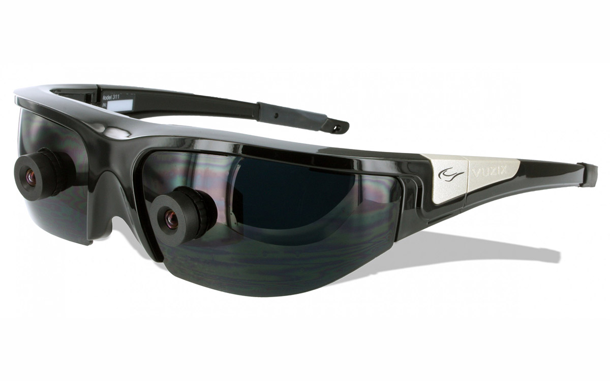
AR glasses generate stereoscopic depth using dual micro-displays (e.g., 500+ PPI OLEDs) projecting slightly offset images—2-5mm horizontal disparity per eye. Brain fuses these via binocular parallax, while waveguides align light paths, creating overlapping 3D visuals that mimic real-world depth perception.
A Picture for Each Eye
your eyes are about 60 to 70 millimeters apart. This gap, known as your interpupillary distance (IPD), means each eye gets a slightly different perspective of the world. Your brain is a powerful processor that automatically merges these two 2D images, calculating the subtle differences to construct a single, rich 3D model of your environment. This process, called stereopsis, is the fundamental principle AR glasses mimic. They don't invent a new way of seeing; they technologically replicate the natural binocular vision you use every second of the day. By presenting meticulously calculated, distinct images to each eye, the glasses trick your brain into perceiving digital objects as solid, tangible elements existing at specific depths within your real-world surroundings. The effectiveness of this illusion hinges on the precision with which the system can deliver these separate image streams.
To create a convincing stereoscopic image, AR glasses use two independent micro-displays or light engines, one dedicated to each eye. Each display generates an image of the same virtual object but from a perspective that matches the viewpoint of that specific eye. The key parameter here is binocular disparity, which is the horizontal shift between corresponding points in the two images. For a virtual object intended to appear 2 meters away, the system calculates the required disparity based on the user's IPD (averaging around 64 mm) and the desired depth plane. If the disparity is too large, the object will appear to float unnaturally or cause eye strain; if it's too small, the object will look flat. Modern waveguides or birdbath optics then channel these two distinct image streams directly into the respective lenses and onto the user's retinas. The physical separation of the optical paths is critical, with typical systems requiring an optical crosstalk of less than 2% to prevent the image for the left eye from 'bleeding' into the right eye, which would severely degrade the 3D effect and cause visual discomfort.
The micro-displays themselves are engineering marvels, often measuring less than 1 inch in diagonal but boasting high resolutions like 1920x1080 pixels per eye or even 4K equivalent to ensure sharp, non-pixelated visuals. A high pixel density, exceeding 3000 pixels per inch (PPI), is crucial for making text and fine details legible. The image for each eye must be refreshed rapidly to keep up with human movement; a refresh rate of 90 Hz is now considered a baseline for comfort, with high-end systems targeting 120 Hz to minimize motion blur.
The system's graphics processing unit (GPU) renders these two parallel image streams in real-time, a task that requires significant computational power. To maintain a seamless blend with reality, the motion-to-photon latency—the delay between a user moving their head and the image updating—must be extremely low, ideally under 20 milliseconds. Any delay greater than that can cause a noticeable lag, breaking the immersion and potentially leading to simulator sickness.
How Your Brain Builds Depth
The visual cortex can process these disparate images in as little as 100-150 milliseconds, fusing them into a single, coherent scene. It's remarkably sensitive, capable of detecting disparity differences as small as 2-10 arcseconds (a tiny fraction of a degree) under ideal conditions.
The process your brain uses is a sophisticated, multi-layered computation. It's not just about merging two pictures; it's about solving a complex correspondence problem to build a depth map.
- Disparity Detection: The first step occurs in the primary visual cortex (V1), where specialized neurons are tuned to detect specific amounts of horizontal disparity between the images from the left and right eyes. Some neurons fire for "near" disparities (crossed), indicating an object is closer than the point of focus, while others fire for "far" disparities (uncrossed). The brain measures this disparity, which can range from 0 arcminutes for objects at infinity to over 100 arcminutes for very close objects, to calculate relative distance.
- Vergence and Accommodation: Your eyes perform a physical dance to aid depth perception. Vergence is the coordinated turning of your eyes inward (convergence) or outward (divergence) to point at an object. The brain receives proprioceptive feedback from the eye muscles, providing a distance estimate. Accommodation is the change in the shape of the eye's lens to focus. In natural vision, vergence and accommodation are linked—you focus and converge at the same distance. This linkage, with a typical response time of 175-400 milliseconds, is a key challenge for AR, as the digital image is often projected at a fixed focal plane (e.g., 2 meters away), while your eyes may be converging as if the object is at 0.5 meters, causing potential conflict and eye strain.
- Monocular and Binocular Cue Integration: Stereopsis is powerful, but the brain seamlessly integrates it with numerous monocular (single-eye) depth cues to reinforce the 3D illusion. The following table compares how these cues work in natural vision and how AR glasses must replicate them to be convincing.
| Depth Cue | Natural Vision Example | AR Glasses Implementation Challenge |
|---|---|---|
| Motion Parallax | Nearby objects appear to move faster than distant ones when you move your head. | Crucial. Requires ultra-low motion-to-photon latency (<20 ms) and precise head tracking (6 degrees-of-freedom) to simulate correctly. |
| Occlusion | A closer object blocks the view of a farther object. | Relatively simple. The rendering engine correctly layers virtual objects in front of or behind real-world objects detected by depth sensors. |
| Shading & Shadows | Light falling on a object creates shadows that define its shape and position relative to surfaces. | Complex. The system must analyze the real-world light source's direction, intensity (~1000+ lux for daylight), and color temperature (5000-6500K) and render virtual shadows accordingly. |
| Texture Gradient | Surfaces appear denser and less detailed with increasing distance. | Managed by the graphics engine, which applies perspective correction and reduces texture resolution for distant virtual objects. |
The brain's final depth perception is a weighted average of all these available cues. If the binocular disparity from the AR glasses is slightly off, but the motion parallax, occlusion, and shadows are perfect, your brain is more likely to accept the illusion. However, inconsistencies, such as a >50 ms delay in updating the image upon head movement, can cause the brain to reject the fusion, leading to a breakdown of the 3D effect and even discomfort. The ultimate goal of AR technology is to achieve a >99% fidelity in replicating these cues to ensure the brain's built-in depth-building machinery works without a hitch.
Showing Two Images at Once
The micro-displays responsible for generating the images are incredibly small, often measuring less than 0.7 inches diagonally, yet they must pack in millions of pixels—typically 1920 x 1080 (Full HD) or higher per eye—to achieve a pixel density exceeding 3000 PPI for crisp visuals. These images are refreshed at a high frequency, with 90 Hz being the current standard to minimize flicker and motion blur, a significant upgrade from the 60 Hz common in older VR headsets. The entire system, from the graphics processor to the final light engine, must operate with extreme precision to ensure the left-eye image only reaches the left retina, and vice-versa. A key metric here is optical crosstalk, which must be kept below 2% to prevent ghosting that can break the 3D illusion and cause significant user discomfort within just 5-10 minutes of use.
AR glasses primarily rely on three core technological approaches to present these separate images, each with distinct advantages and trade-offs in terms of image quality, form factor, and power consumption.
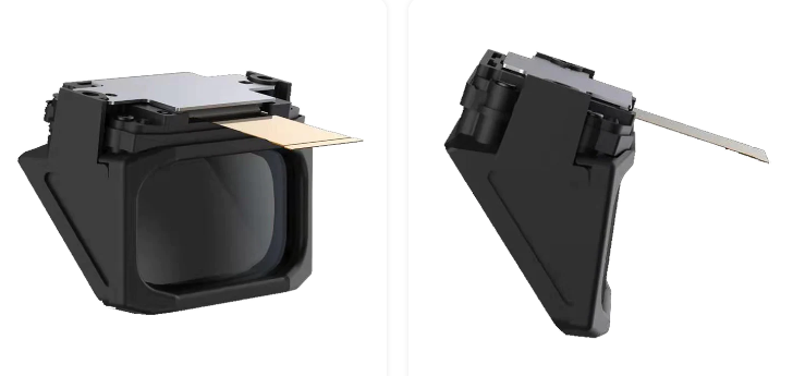
- Waveguide-Based Displays: This is the most common architecture in modern, sleek AR glasses. Here, a single micro-display (often an LCoS or micro-OLED panel measuring around 0.5 inches) projects light into a thin, transparent piece of glass or plastic—the waveguide. This slab, which can be as thin as 1-1.5 mm, uses a combination of diffractive (e.g., surface relief gratings) or reflective optics to "pipe" the light down its length through total internal reflection. At the correct points, out-coupler gratings with a precision on the nanoscale (e.g., a period of 300-500 nanometers) redirect the light toward the user's eye. The primary advantage is the ability to create a large virtual image while keeping the physical glasses compact and lightweight, often under 100 grams. However, waveguides typically have an optical efficiency of only 1-5%, meaning a significant amount of light is lost, requiring very bright micro-displays capable of outputs exceeding 1,000,000 nits to produce a readable 1,000-nit image in daylight conditions.
- Birdbath Optics: This design offers a simpler optical path, often resulting in better color saturation and a wider field of view (often 50-60 degrees), but at the cost of a bulkier form factor. In a birdbath design, the micro-display is typically mounted on the temple of the glasses, projecting light upward onto a 45-degree angled beamsplitter. This semi-transparent mirror reflects the light down toward the wearer's eye while still allowing a view of the real world. The optical path resembles a bird looking down into a bowl of water, hence the name. While generally more efficient than waveguides, with less light loss, the design necessitates a deeper physical profile, making the glasses look more like traditional goggles. The combiner lens in these systems can be several centimeters thick, increasing the overall weight to 150-200 grams or more, which can impact comfort during extended use beyond 30 minutes.
- Laser Beam Scanning (LBS): LBS takes a radically different approach. Instead of illuminating a traditional pixel-based display, it uses tiny MEMS (Micro-Electro-Mechanical Systems) mirrors, each measuring less than 1 mm in diameter, to scan red, green, and blue laser beams directly onto the retina. These mirrors oscillate at incredibly high frequencies, sometimes exceeding 20,000 times per second, to raster-scan the image. The key advantage of LBS is its potential for "infinite focus," as the laser beams are collimated, which can help mitigate the vergence-accommodation conflict that plagues other display types. It can also be very power-efficient, potentially reducing power consumption for the display subsystem to under 1 watt.
Designers must balance the field of view (FoV), which can range from a modest 30 degrees to an immersive 70 degrees, against the eyebox—the volumetric space where the user's eye can still see the full image, typically a 10x12 mm rectangle. A larger eyebox, often >8 mm, provides more comfort for users with different facial structures but is optically more challenging to achieve. Furthermore, all these systems must be precisely aligned during manufacturing, with tolerances often within 10-20 microns, to ensure the virtual image is stable and correctly positioned for the wearer. The ongoing evolution in this space is focused on pushing the resolution higher, the form factor smaller, and the optical efficiency greater to create a more seamless and comfortable 3D experience.
Adding Depth with Light and Shade
AR glasses must therefore replicate the complex interplay of light in the real world. This begins with environmental understanding: the system uses its front-facing cameras and sensors to analyze the ambient light conditions in real-time. It measures the color temperature (e.g., 3000K for warm indoor lighting vs. 6500K for overcast daylight), intensity (which can range from 1000 lux in a bright office to over 10,000 lux outdoors), and most critically, the primary direction of the dominant light source. A deviation of even 15-20 degrees in the calculated light direction can make a virtual object appear blatantly "pasted on," as the shadows it casts will conflict with those in the real environment. The rendering engine must process this data and re-calculate the virtual scene's lighting every time the frame updates, typically at 90 Hz, to maintain a convincing illusion as the user moves.
The core of this process is real-time rendering. For a virtual cube placed on a real table, the graphics processing unit (GPU) performs a series of rapid calculations. First, it uses the environmental data to simulate direct lighting. The brightness of each pixel on the virtual object is computed based on its angle relative to the virtual light source, which is aligned with the real-world source. A surface facing directly towards the light might be rendered at 90% brightness, while a surface at a 45-degree angle might drop to 60%. This creates a basic sense of form. Next, the system generates shadows. This is computationally intensive, often requiring techniques like shadow mapping. The GPU renders the scene from the perspective of the light source to create a depth map, and any part of the virtual object (or real-world geometry detected by depth sensors) that is occluded from this light perspective is cast in shadow. The softness of the shadow is crucial; a sharp, hard shadow implies a small, bright light source, while a soft, diffused shadow suggests a large or overcast light source. The rendering engine adjusts the shadow's penumbra region (the soft edge) based on the estimated size and distance of the real light source, a parameter that might vary from a 2-pixel blur radius for a spotlight to a 15-pixel blur for ambient office lighting.
The engine calculates this contact shadow with a high degree of precision, often darkening the area by 10-15% within a 0.5-2 centimeter range. Similarly, the virtual object must exhibit specular highlights—the bright, shiny reflections of the light source. The intensity and size of these highlights are determined by the virtual material's properties. A metallic material might have a sharp, bright highlight reflecting 70-80% of the light, while a matte plastic would have a broader, dimmer highlight of maybe 20-30%. The system must also account for reflectivity. A glossy virtual object should faintly reflect its real-world surroundings. This is achieved by using the camera feed to create a dynamic 360-degree environment map that is projected onto the shiny surfaces of the virtual object, with a reflection intensity of perhaps 5-10% to avoid looking like like a mirror. All these calculations must be performed within a strict 11-millisecond budget per frame to maintain a 90 Hz refresh rate, placing a significant load on the GPU that can increase power consumption by 3-5 watts compared to rendering flat, unshaded objects.
| Lighting Phenomenon | Real-World Perception | AR Glasses Simulation Technique |
|---|---|---|
| Shadows | Naturally occur when light is blocked. Physically accurate. | Dynamic Shadow Mapping. Rendered from a virtual light source aligned with real-world direction. Softness is a tunable parameter. |
| Ambient Occlusion | Subtle darkening in corners and contact points due to scattered light being occluded. | Screen-Space Ambient Occlusion (SSAO). A screen-based approximation that darkens pixels based on depth buffer geometry, adding ~2-3 ms of render time. |
| Specular Highlights | Bright spots on shiny surfaces indicating light source location and size. | Phong or Physically-Based Rendering (PBR). Calculated per pixel based on material shininess (e.g., a roughness value of 0.1 for glossy, 0.8 for matte) and light vector. |
| Reflections | Surfaces mirror their environment based on reflectivity. | Dynamic Environment Mapping. A coarse, real-time captured panorama from the cameras is mapped onto reflective virtual surfaces with a 5-15% blend. |
The ultimate goal is to achieve a >95% perceptual match between the virtual object's lighting and the real scene's lighting. Even a 10% error in average shadow darkness or a 100 Kelvin error in the color temperature of the reflected light can be subconsciously detected by the viewer, breaking the illusion of cohesion.
Blending Real and Virtual
Its primary job is to allow over 85% of the real-world light to pass through with minimal distortion while simultaneously reflecting the light from the micro-display into the eye. This dual function creates the blend. The key performance metrics here are see-through transparency and virtual image brightness. In bright outdoor environments exceeding 10,000 lux, the virtual image must be exceptionally bright, often requiring a display brightness of 1000 nits or more to remain visible. Conversely, the combiner itself must have very high optical efficiency; even a 5% loss in real-world light can make the environment appear unnaturally dim, forcing the display to consume more power to maintain contrast. The entire system must dynamically adjust the virtual image's luminance based on ambient light sensors, often making 100 adjustments per second to changes in lighting.
For waveguide-based systems, this involves diffractive optical elements (DOEs) with grating periods measured in nanometers (e.g., 350 nm). These nanostructures are engineered to be selectively reflective, targeting the specific wavelengths of the micro-display's red, green, and blue lasers or LEDs. The efficiency of this process is paramount. A typical waveguide might have a light efficiency of only 3%, meaning 97% of the light from the display is lost within the waveguide before it reaches the eye. This massive inefficiency is why the display engine must be so powerful to begin with. The other critical property is light leakage. A high-quality combiner ensures that the virtual image is only visible to the intended eye, with optical crosstalk maintained below 2%. If light from the right-eye display leaks into the left eye, it creates a ghosted, double image that severely degrades the stereo effect and can cause eye strain within 2-3 minutes of use. The alignment of these optical elements during manufacturing must be precise to within 10 microns to ensure the virtual image is perfectly stable and aligned with the real world.
The challenge of blending is fundamentally a battle against unwanted light. The goal is to maximize the signal (virtual image) while minimizing the noise (distortions of the real world) and preventing interference between the two image channels. Key parameters include a >85% transmittance of real-world light, a <5% wavefront distortion to avoid blurring reality, and a <2% crosstalk between the left and right eye optical paths.
A time-of-flight (ToF) sensor or LiDAR scanner, with an effective range of 0.1 to 5 meters and an accuracy of +/- 1% of the measured distance, continuously maps the environment. This depth map must be processed and integrated with the rendering pipeline with a total latency of under 20 milliseconds. When you raise your hand, the system detects its 3D position and instructs the rendering engine to stop drawing the virtual object on the pixels that correspond to your hand's location. A latency exceeding 50 ms results in a noticeable delay where the virtual object appears to "swim" over your hand before being correctly occluded, instantly breaking the illusion.
Adjusts for Your Movement
The human brain is incredibly sensitive to this lag; if it exceeds 20 milliseconds, the virtual object will appear to "swim" or "jitter" relative to the real environment, causing a disconnect that can lead to disorientation and nausea in as little as 30 seconds of use. To achieve this, AR glasses employ a sensor fusion system that typically samples data at frequencies ranging from 100 Hz to an astonishing 2000 Hz, processing linear acceleration, rotational velocity, and visual features to build a real-time model of your movement. This high-frequency data capture is essential because a human head rotation can reach speeds of over 300 degrees per second during a quick turn. A system updating at only 60 Hz would miss critical motion data between frames, resulting in a noticeable and disruptive lag that breaks the immersive illusion.
The primary component is an Inertial Measurement Unit (IMU), a tiny chip—often smaller than 4x4 mm—that contains a 3-axis accelerometer and a 3-axis gyroscope. The gyroscope, which measures rotational velocity, is particularly crucial, with high-end models sampling at 2000 Hz and providing an angular random walk (a measure of drift) of less than 0.1 degrees per square root hour. However, IMUs alone suffer from drift: tiny errors in measurement that accumulate over time, causing the virtual world to slowly shift out of alignment. To correct for this, the system uses outside-in or inside-out camera tracking. One or more monochrome global shutter cameras, typically with a resolution of 640x480 pixels and a wide 150-degree field of view, capture the environment at 60 frames per second. A dedicated vision processor then analyzes these images to identify and track natural feature points—distinct visual patterns like the edge of a picture frame or a keyboard corner. By tracking hundreds of these points simultaneously, the system can correct the IMU's drift with an accuracy of 1-2 centimeters in position and 0.1-0.5 degrees in orientation.
The real challenge lies in fusing this data coherently. This is done through a sensor fusion algorithm, most commonly a Kalman filter or a complementary filter, which runs on a dedicated processor. This algorithm continuously weighs the inputs from the different sensors. The IMU provides high-frequency (>1000 Hz) but drift-prone data for short-term motion prediction, while the cameras provide lower-frequency (60 Hz) but absolute data for long-term stability correction. The filter's output is a highly precise and stable 6 Degrees of Freedom (6DoF) pose—comprising X, Y, Z position and roll, pitch, yaw orientation—which is fed to the rendering engine. The entire process, from sensor sampling to pose calculation, must be completed in under 5 milliseconds to leave sufficient time for the graphics engine to re-render the scene within the total 20 ms latency budget.
|
Sensor Type |
Key Function |
Sample Rate / Frequency |
Key Performance Parameter |
Typical Value |
|---|---|---|---|---|
|
MEMS Gyroscope |
Measure rotational velocity |
1000 - 2000 Hz |
Angular Random Walk |
< 0.1 °/√hr |
|
MEMS Accelerometer |
Measure linear acceleration |
1000 - 2000 Hz |
Velocity Random Walk |
< 0.1 m/s/√hr |
|
Tracking Camera |
Visual-inertial odometry |
30 - 60 Hz |
Feature Tracking Accuracy |
< 0.5 pixel error |
|
Depth Sensor (ToF/LiDAR) |
Map environment geometry |
5 - 30 Hz |
Depth Accuracy at 3m |
± 1 - 3 cm |
When you walk towards a virtual coffee cup on a real table, the system detects your forward motion of, for example, 1.2 meters per second. It instantly calculates the changing perspective and re-renders the cup, making it appear larger at a rate that precisely matches your approach. If you tilt your head 15 degrees to the left, the gyroscope detects the rotation within 1 millisecond, and the rendering engine adjusts the virtual scene accordingly, ensuring the cup remains correctly positioned on the table. Any failure in this chain, such as a camera's exposure being too slow in a dark room (below 10 lux), causing it to lose track of features, will result in the system relying solely on the drifting IMU.
Read more

Augmented Reality (AR) systems use various optical solutions to overlay digital information on the real world. The industry adopts prism scheme, off-axis optical scheme, free surface scheme, birdba...

Augmented reality (AR) is a rapidly developing technology that is changing the way we interact with the world around us. AR applications overlay virtual content onto the real world, requiring displ...


Leave a comment
This site is protected by hCaptcha and the hCaptcha Privacy Policy and Terms of Service apply.