


Inside Character OLED Modules: From HD44780 Compatibility to Advanced Features
Character OLED modules support HD44780 protocols (parallel/I2C), using standard commands (cursor set, clear). Advanced features: 128x64 res, 1000:1 contrast, backlit control, blending legacy compatibility with low-power, high-clarity use in instruments.
Core Basics
While a standard 16x2 LCD module consumes a constant ~0.5 watts to power its fluorescent backlight, a comparable OLED module typically draws only ~0.05 watts because each of its microscopic pixels produces its own light. This efficiency gain is most pronounced in applications where the display is mostly off, with static power dropping to well under 1 milliwatt. The core compatibility is maintained by an onboard chip, most commonly the Solomon Systech SSD1306 controller, which is explicitly designed to emulate the HD44780's instruction set and the crucial 8-bit parallel or I2C/SPI communication protocols.
The controller dedicates a 256-byte RAM buffer to represent the entire screen. For a standard 2-line, 16-character display, this buffer is logically divided into two 80-byte segments: DDRAM1 (0x00-0x4F) for the first line and DDRAM2 (0x40-0x8F) for the second. However, only the first 16 bytes of each segment are physically mapped to the visible display area.
Writing a character's ASCII code (e.g., 'A' is 0x41) to an address like 0x02 places it in the third position on the top line. The controller's internal oscillator runs at a high frequency, typically around 400kHz to 1MHz for the core logic, which determines the pixel refresh rate and ensures a flicker-free image. The controller also manages the complex multiplexing required to address the 128 segments and 64 commons of the actual OLED panel, a task transparent to the user but essential for the display's physical operation.
The controller also contains a separate 64-byte Character Generator RAM (CGRAM) which allows a user to define up to eight custom 5x8 pixel characters, storing their bitmap patterns for later use just like the standard 240 characters in the fixed ROM. The entire system is designed for a long operational life, with manufacturers specifying a typical lifetime of 10,000 to 30,000 hours before the organic compounds degrade to half their original brightness, a figure highly dependent on the average pixel-on percentage and operating temperature.
SPI vs I2C
If your microcontroller is rich in I/O pins and you need to update the display content very rapidly—perhaps for a custom animation or a frequently changing value—SPI is the clear winner, capable of clock speeds up to 10 MHz on many modules. However, if you're working with a small-footprint MCU like an ATtiny85 or an ESP8266 where every single I/O pin is precious, the 2-wire I2C bus (requiring only SDA and SCL, plus power) becomes incredibly attractive, despite its slower maximum data rate, typically 400 kHz in Fast Mode or 1 MHz in Fast-Mode Plus.
A full SPI implementation requires four distinct electrical lines: MOSI (Master Out, Slave In), MISO (Master In, Slave Out), SCLK (Serial Clock), and CS (Chip Select). The MISO line is often omitted on display modules because data rarely flows back to the MCU, reducing the practical pin count to three. The CS pin is critical; it allows you to have multiple SPI devices on the same bus, toggling this pin low to activate just one device at a time. I2C, in contrast, uses a shared bus architecture. Every device on the same two wires (SDA and SCL) has a unique 7-bit address, usually configurable within a small range (e.g., 0x3C or 0x3D) via a solder jumper on the module's PCB.
|
|
|
|
|---|---|---|
|
|
|
|
|
|
|
|
|
|
|
|
|
|
|
|
|
|
|
|
|
|
|
|
In an SPI write operation, after pulling the CS line low, the MCU sends a continuous stream of bits synchronized to a clock signal that can run at 1 MHz or even 10 MHz. There's almost no protocol overhead beyond the data itself. A full 32-character screen update might take just 1 to 2 milliseconds. I2C, however, packages data with a significant header. For every byte of data you want to send, the protocol adds a start condition, the 7-bit slave address plus a write bit, and an acknowledgement bit.
OLED vs LCD
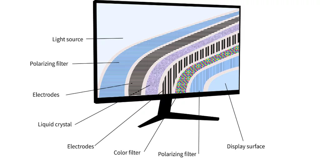
An LCD works by manipulating a liquid crystal solution—roughly 0.1mm thick—sandwiched between two polarized layers, twisting to block or allow light from a constant 3.0V to 4.2V LED backlight. This process is inherently inefficient because the backlight is always on, consuming a relatively constant 0.3 to 0.5 watts regardless of whether the screen shows a single character or is completely full. An OLED, in contrast, is an emissive technology. Each microscopic sub-pixel is an organic light-emitting diode that produces its own light when a current is applied. A 16x2 character OLED module typically consumes only 0.03 to 0.06 watts when active, with power usage directly proportional to the number of lit pixels; displaying just two characters might use only 10% of the power needed for a full screen.
LCDs, with their always-on backlight, struggle with true blacks, resulting in a contrast ratio typically in the range of 100:1 to 500:1. The viewing angle is another critical differentiator. While modern Twisted Nematic (TN) LCDs used in these modules have improved, they still experience significant color shift and contrast loss beyond 120 degrees off-center. OLEDs maintain nearly perfect contrast and clarity at viewing angles exceeding 160 degrees.
|
|
|
|
|---|---|---|
|
|
|
|
|
|
|
|
|
|
|
|
|
|
|
|
|
|
|
|
|
|
|
|
|
|
|
|
OLEDs have a significant advantage in low-temperature applications. Their response time remains virtually instantaneous down to -40°C, making them ideal for outdoor instrumentation or freezer controls. Standard LCDs suffer from a drastically increased response time below 0°C, with the liquid crystals becoming sluggish, which can cause noticeable ghosting or smearing.
The liquid crystal fluid itself can freeze solid at temperatures approaching -20°C to -30°C, permanently destroying the display. However, LCDs have a key advantage in high-temperature, high-brightness environments. They are less susceptible to permanent image retention (burn-in) under prolonged static display conditions. The organic materials in an OLED slowly degrade with use, and their lifetime to half-brightness is often rated at 10,000 to 30,000 hours, whereas an LCD's lifespan is primarily determined by its backlight, which can last 50,000 hours or more.
Control Codes
There are about 11 core instructions that make the display work, each identified by a unique hexadecimal value. Sending the correct sequence is critical; for example, the initialization routine requires a specific series of 6 to 8 commands sent with precise timing delays of 50 microseconds to 5 milliseconds to properly power up the controller and stabilize the voltage for the OLED pixels.
The Clear Display command (code 0x01) does more than just wipe the screen. It writes a space character (ASCII 0x20) to all 80 DDRAM locations and resets the address counter back to 0x00. This operation is relatively slow, taking approximately 1.64 milliseconds to complete because it must cycle through the entire memory. Similarly, the Return Home command (0x02) also sets the address counter to 0x00, but it does not alter the DDRAM content; it simply moves the cursor. This command also has a fixed execution time of 1.64 ms.
-
Clear Display: 0x01
-
Return Home: 0x02
-
Entry Mode Set: 0x04(base), with bits for cursor direction and display shift.
-
Display On/Off Control: 0x08(base), with bits for the display, cursor, and blinking.
-
Cursor/Display Shift: 0x10(base), controls shifting the entire display or just the cursor.
-
Function Set: 0x20(base), sets data interface length, number of lines, and font.
-
Set CGRAM Address: 0x40(base), followed by the 6-bit CGRAM address (0-63).
-
Set DDRAM Address: 0x80(base), followed by the 7-bit DDRAM address (0-127).
The Entry Mode Set command (0x04) is crucial for determining how the cursor behaves after each character write. By setting the Increment bit, you tell the controller to automatically advance the cursor address by +1 after each character, which is the normal left-to-right flow. If you clear this bit, the address decrements by -1, causing text to flow from right to left. You can also enable an "auto-shift" of the entire display, which makes it seem like the cursor stays fixed while the display moves. The Display On/Off Control command (0x08) is your main power switch. You can turn the entire pixel array on or off without losing the data in DDRAM. This is different from the module's power pin. When the display is off, power consumption can drop from the active 0.05 watts to a standby level of less than 0.001 watts. This command also controls the cursor visibility and its blink function, which typically has a blink frequency of about 2.5 Hz (a 400-millisecond period).
For positioning text, the Set DDRAM Address command (0x80) is essential. You must add the desired memory address to this base value. For a 16x2 display, the first line starts at address 0x00 and the second line at 0x40. To place the cursor at the fifth position on the second line, you send the command 0x80 + 0x40 + 4 = 0xC4. The Function Set command (0x20) is typically sent once during initialization to configure the data interface (8-bit vs 4-bit), the number of display lines (1 or 2), and the character font (5x8 or 5x10 dots). Using the 5x10 font on a 2-line display usually limits you to displaying only the first line because the controller needs more scan lines to render the taller characters.
CGRAM Use
The standard character set in the display's ROM is fixed, containing 240 predefined characters including alphanumerics and common symbols. The Character Generator RAM (CGRAM) is a small, user-accessible memory block that allows you to design and store your own graphics. This 64-byte space is partitioned to hold exactly eight custom characters, with each character's pattern consuming 8 bytes of data. The primary application for CGRAM is creating simple icons, logos, or special symbols that aren't part of the standard character map. For instance, you can design a 5x8 pixel bell icon for a notification, a Wi-Fi signal strength indicator with 4 bars, or a miniature logo.
The step-by-step process for creating a custom character is as follows:
-
Calculate the Bitmap: Design your character on a 5x8 grid. Each of the 8 rows is represented by 1 byte, where the 5 least significant bits (values 0-31) define the pixel pattern. A value of 31 (0b11111) creates a fully lit row.
-
Set the CGRAM Address: Send the command 0x40 + (N * 8), where
Nis the character slot number from 0 to 7. -
Write the 8 Bytes: Send 8 consecutive data bytes, one for each row of the character.
-
Return to DDRAM: Send the 0x80 command to set the address counter back to the display memory (DDRAM) for normal text writing.
-
Display the Character: To show your custom character, send the data byte corresponding to its slot number: 0 to 7.
The starting addresses for each slot are separated by 8 bytes. The character in slot 0 lives at addresses 0x00 to 0x07, slot 1 from 0x08 to 0x0F, and so on up to slot 7 at 0x38 to 0x3F. When you send the Set CGRAM Address command, you are setting an internal pointer to one of these 64 specific locations. The execution time for each Set CGRAM Address or data write command is typically 37 to 50 microseconds, so a well-written routine to define a single character will take just over 400 microseconds to complete.
The controller is designed to interpret the data bytes 0x00 to 0x07 and 0x08 to 0x0F as references to CGRAM, not the standard ROM font. In practice, most libraries use the range 0x00 to 0x07. So, after defining a symbol in slot 2, writing the data byte 0x02to DDRAM will render your custom graphic.
Advanced Features
While HD44780 compatibility provides a solid foundation, the OLED controllers like the SSD1306 include several advanced features that go far beyond the original specification. These functions allow for direct hardware-level control over the display's behavior, enabling optimizations for power consumption, visual effects, and system integration that aren't possible with a standard LCD. One of the most significant is the ability to manipulate the display's internal charge pump regulator and pre-charge periods. The charge pump is a DC-DC converter that generates the high voltage (typically around 7.0V to 9.0V) required by the OLED pixels from a lower logic supply voltage of 3.3V.
The command 0x8Dis followed by a byte where bit 2enables or disables the charge pump. For stable operation at 3.3V, you must send the sequence 0x8D, 0x14during initialization to turn it on. This is a mandatory step for most modules, not an optional one.
The controller allows you to set the contrast level with 256 steps of granularity using a single command. The command 0x81is followed by a second byte that sets the contrast value, where 0x00is the dimmest and 0xFFis the brightest. The effective current drawn by the display scales almost linearly with this value. At a contrast setting of 0x7F(approximately 50%), the power consumption will be roughly half of what it is at the maximum setting of 0xCF (a common default). This allows for dynamic power saving; for example, an instrument in a dark room can run at a contrast level of 0x40to reduce power consumption by over 60% compared to full brightness, while a device used in sunlight can be temporarily boosted to 0xFFfor better visibility.
A related setting is the pre-charge period, configured with command 0xD9. This command controls the duration of the pre-charge phase for the pixel capacitors, which affects the sharpness of the pixel transition and can be tuned to reduce ghosting. The default period is often around 2 clock cycles for phase 1 and 13 clock cycles for phase 2.
For instance, a vertical scroll command will define a starting row of 0and an ending row of 7for a single line of 5x8 pixel characters, and then set a scroll speed of 6 frames per step. Once the 0x2Fcommand is sent to activate the scroll, the display will autonomously shift the content, creating a smooth animation. This is far more efficient than software scrolling, which would require the MCU to rewrite the entire DDRAM contents every few tens of milliseconds, consuming valuable processor cycles and keeping the communication bus active.
Read more
PMOLED uses row-column addressing (no TFTs), driving pixels via AC pulses (~10V). Found in 0.96” 96x64 displays (150cd/m²), powering smartwatches/calculators with <5mA power, ideal for compact, ...
Though AHVA, PLS, and e-IPS all leverage IPS tech for wide ~178° viewing angles, they differ subtly: AU Optronics’ AHVA often hits higher contrast (~1000:1) for richer blacks; Samsung’s PLS typical...
Leave a comment
This site is protected by hCaptcha and the hCaptcha Privacy Policy and Terms of Service apply.