LCDs (Liquid Crystal Displays) use electric signals to control the state of polarized light, creating images. So, before diving into how LCDs display images, let’s get a grasp on the basics of light polarization.
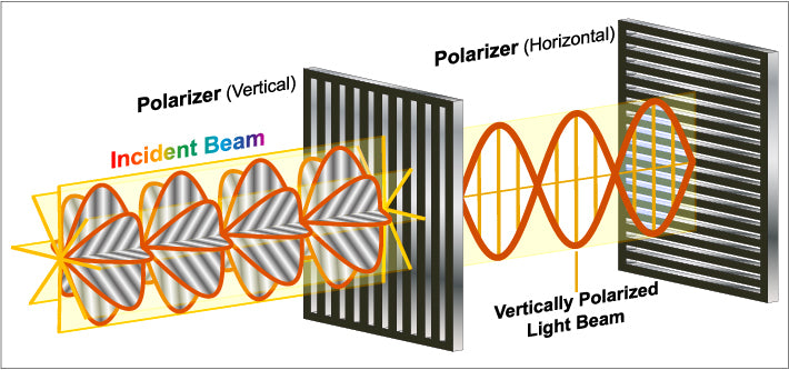
Electromagnetic theory tells us that as electromagnetic waves travel, the electric field vector E , magnetic field vector B , and the wave velocity V are all perpendicular to each other. This means electromagnetic waves are transverse waves, and the phenomenon of light polarization proves that light is also a transverse wave. In general light sources, light waves are emitted from numerous molecules or atoms, so no single direction of light vector is dominant over others, making such light “natural light.” At any moment, each light vector can be split into two perpendicular light vectors. If one direction of the light vector is dominant in the light beam, that light is polarized light. The plane formed by the vibration direction of the polarized light and its propagation direction is called the plane of polarization. The process of obtaining polarized light from natural light is called polarization, and devices that achieve this are called polarizers. Polarizing films are a common type of polarizer. When natural light hits a polarizing film, it only allows light vibrating in a specific direction to pass through, known as the direction of polarization or transmission direction, usually indicated by a double-headed arrow. Polarizing films can not only convert natural light to polarized light but also check if a light beam is polarized. A polarizing film used for this purpose is called an analyzer.
Ideally, when the analyzer’s polarization direction is at a 90° angle to the incident polarized light’s direction, the transmitted light intensity for orthogonal polarizers is zero. When the angle is 0°, the transmitted light intensity for parallel polarizers is 50% of the incident light.
An LCD can be thought of as a sandwich structure, with a layer of liquid crystal between two polarizing films oriented perpendicularly to each other. The liquid crystal’s orientation can be controlled by an external electric field. Natural light becomes vertically polarized after passing through a polarizer (one of the polarizing films). This polarized light then passes through the liquid crystal, which, without any applied electric field, maintains its original arrangement. Due to the optical anisotropy of the liquid crystal and the arrangement of its molecules, the polarization direction changes from vertical to horizontal. The horizontally polarized light aligns with the transmission axis of the analyzer and thus passes through the LCD. This mode, where light passes through the LCD without an electric field (0V), is called “Normal White” (NW) mode. Similarly, when a voltage is applied to the liquid crystal, the molecules change from a twisted arrangement to a vertical one. The polarization direction of the incident polarized light remains unchanged, causing it to be perpendicular to the analyzer’s transmission axis and blocked, resulting in no light passing through the LCD. Depending on the liquid crystal arrangement, when no electric field is applied, and the incident light cannot pass through, this display mode is called “Normal Black” (NB).
The basic principle of LCDs explained above only describes the light either passing through or being completely blocked, resulting in two states (brightest and darkest). In practical applications, LCD panels use TFTs (Thin Film Transistors) to switch and apply different voltages to each pixel. The liquid crystal molecules rotate differently under various voltages, affecting the polarization of the light to different extents, resulting in different brightness levels of the outgoing light. This allows for multi-gray-scale image display. If each pixel is combined with a color filter (CF), it can display colored images.
Read more

Thin Film Transistor (TFT) LCDs are primarily composed of the following components: 1. Backlight: Provides the initial light source necessary for the display. The backlight system typically incl...

Liquid crystals (LCs) occupy a fascinating niche between solids and liquids, crucially affecting their behavior based on temperature changes. In the realm of displays, LCs are predominantly thermo...


Leave a comment
This site is protected by hCaptcha and the hCaptcha Privacy Policy and Terms of Service apply.