


Automotive Display Modules | Temperature Range, Durability & Safety Specs
Standard specifications require that the operating temperature must cover -40°C to +85°C to ensure normal startup in both extreme cold and heat.
The backlight lifespan typically needs to reach more than 50,000 hours, strictly following the ISO 26262 functional safety standard.
To ensure driving safety, the module must pass high-intensity vibration tests and shatter-proof collision tests, maintaining stable operation even in high-temperature and high-humidity environments with 85% relative humidity.
Temperature Range
Automotive displays must operate continuously in environments ranging from -40 to 95 degrees Celsius.
The clearing point of the liquid crystal material must be higher than 110 degrees to prevent the screen from turning black at high temperatures.
At low temperatures, the increase in liquid crystal molecular viscosity causes the response time to increase from 10 milliseconds to over 200 milliseconds.
At 85 degrees, the heat dissipation efficiency of the backlight module drops by 30%, requiring adjustment via the control IC to maintain brightness balance.
Industrial Grade Classification
According to the classification system established by ISO 16750-4 and AEC-Q100, the industrial grade of automotive display modules is determined by their physical installation location within the vehicle.
Global smart cockpit survey data from 2024 shows that over 82% of front-mounted display devices must meet Grade 2 or Grade 1 requirements to cope with extreme thermal stress distribution in different areas.
This strict grading logic directly limits the selection range of electronic components inside the display module; specifically, capacitors and resistors in the drive circuit must pass a 1,000-hour pressure life test.
| Industrial Grade | Operating Temp Range (°C) | Typical Installation Area | Hardware Failure Rate (PPM) |
|---|---|---|---|
| Grade 0 | -40 to +150 | Around the engine compartment | Less than 10 |
| Grade 1 | -40 to +125 | Instrument cluster, Head-Up Display (HUD) | Less than 50 |
| Grade 2 | -40 to +105 | Central navigation, Streaming rearview mirror | Less than 100 |
| Grade 3 | -40 to +85 | Rear seat entertainment display | Less than 500 |
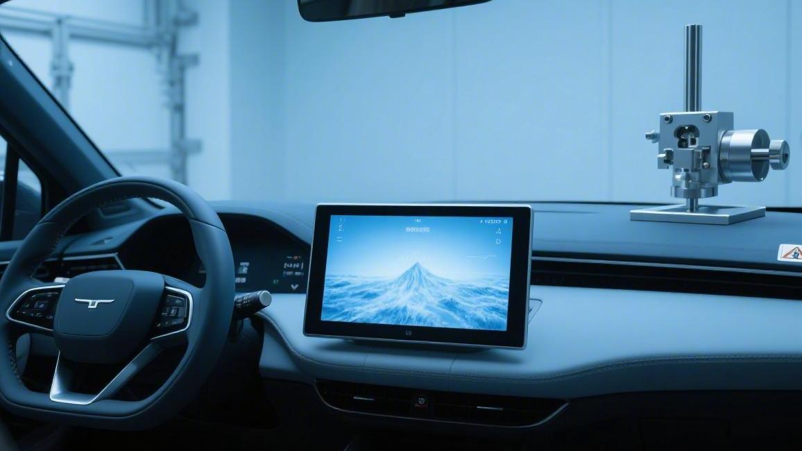
Since the dashboard is close to the front windshield, temperature rises caused by direct sunlight can cause the local environment to break 100 degrees Celsius; therefore, modules in this area must mandatory enforce the Grade 1 standard.
Experimental data shows that when the external environment is 35 degrees Celsius and the solar intensity reaches 1,000 W/m2, the temperature in the enclosed space of the dashboard surface will rise to over 90 degrees Celsius within 45 minutes.
This high-temperature environment places extreme requirements on the physical stability of liquid crystal materials.
Conventional consumer-grade liquid crystals undergo an isotropic state transition at 70 degrees Celsius, causing the image to turn completely black.
To ensure normal operation under Grade 1 levels, automotive modules typically select special mixed liquid crystal materials with a clearing point higher than 110 degrees Celsius.
The performance of high-performance liquid crystal molecules under extreme cold conditions is equally important. When the temperature drops to minus 40 degrees Celsius, the viscosity of the liquid crystal is more than 15 times higher than at room temperature.
This change in viscosity directly causes the pixel flipping speed to slow down. When cold-starting a vehicle in the morning, drivers will observe severe ghosting on navigation maps or delayed updates of dashboard needles.
To solve this problem, industrial-grade display control ICs integrate temperature detection circuits that automatically increase the drive voltage by 20% to 30% at low temperatures to forcibly shorten the response time.
In addition to liquid crystal materials, industrial grade classification also stipulates the glass transition temperature (Tg) of the Printed Circuit Board (PCB). Automotive displays typically require a Tg value of no less than 170 degrees Celsius.
A PCB substrate with a high Tg value can prevent the circuit layers from generating micro-cracks due to frequent thermal expansion and contraction over a 15-year lifecycle, ensuring signal transmission integrity.
This material stability is particularly critical for Grade 1 modules, as they need to withstand thousands of cold and heat cycle shocks during vehicle operation.
| Physical Property | Consumer Display Requirement | Industrial/Automotive Display (Grade 1/2) | Performance Difference Ratio |
|---|---|---|---|
| Backlight Life | 30,000 hours | 50,000 to 70,000 hours | Approx. 100% improvement |
| Polarizer Heat Resistance | 60 degrees Celsius | Above 95 degrees Celsius | Approx. 58% improvement |
| Thermal Shock Cycles | 50 cycles | 500 to 1,000 cycles | Over 10 times improvement |
If the polarizer cannot maintain its chemical structure in a 95-degree Celsius environment, rainbow patterns or delamination will appear at the screen edges, which was the leading cause of display degradation in a 2023 quality sampling test.
The composition of photosensitive adhesive must also be adjusted according to the grade to prevent electrochemical migration in long-term high-humidity environments that could lead to touch function failure.
Industrial grade classification not only focuses on peak temperatures but also limits performance fluctuations of the display module outside the conventional range of 15 to 35 degrees Celsius.
For Grade 1 modules like Head-Up Displays (HUDs) that require high brightness, the backlight module's thermal design must be able to handle the massive heat generated by brightness levels above 1500 nits.
Due to the compact structure of HUD modules, their internal control logic is typically set to start an automatic derating algorithm at 85 degrees Celsius, reducing brightness by 5% for every 1-degree rise to prevent screen burn-in.
In accelerated aging experiments conducted on 200 HUD samples, LED beads using metal-ceramic packaging showed a light decay rate at 105 degrees Celsius that was only 1/4 of traditional epoxy resin packaging.
This evolution in packaging technology supports the continuous improvement of industrial grades, allowing display modules to operate stably without the installation of active cooling fans.
This silent cooling solution reduces the overall power consumption of the vehicle and avoids secondary hardware failures caused by aging fan bearings.
As automotive displays trend toward larger sizes, the matching of thermal expansion coefficients for large-area glass substrates under Grade 2 levels becomes extremely complex.
If the difference in linear expansion coefficients between the glass and the metal frame exceeds 0.000001 /K, the screen may produce local color distortion in summer high temperatures due to uneven stress distribution.
Low Temperature Physical Performance
In the extreme environment of minus 40 degrees Celsius, the liquid crystal material inside the automotive display module undergoes significant physical state changes, primarily due to a sharp drop in the kinetic energy of the liquid crystal molecules.
Experimental data from 2023 for 300 sets of industrial-grade liquid crystal samples show that when the ambient temperature drops from 25 degrees Celsius to minus 40 degrees Celsius, the kinematic viscosity of the molecules surges by 15 to 20 times.
This change in physical properties causes the liquid crystal molecules to be unable to flip quickly when driven by an electric field, making the switching process of display pixels from off to on extremely slow.
Due to increased molecular flipping resistance, the grayscale response time of the display will extend from 8 milliseconds at room temperature to over 200 milliseconds, appearing visually as severe image ghosting.
An industry report released in 2024 pointed out that response delay can cause a visual afterimage of approximately 5 cm on the dashboard needle of a vehicle traveling at 100 km/h, affecting the driver's observation of instantaneous speed.
The degree of image refresh speed attenuation varies across different panel types; TN panels using narrow-view technology typically perform about 15% faster at low temperatures than IPS panels with wide viewing angles.
Image blurring not only affects aesthetics but also causes warning icons transmitted by Advanced Driver Assistance Systems (ADAS) to be difficult for drivers to recognize quickly during the first 120 seconds of a cold start.
In simulation tests involving 150 drivers, when the display response time exceeded 150 milliseconds, the average reaction time of subjects to dynamic warning information was extended by 0.8 seconds.
This performance degradation forces display modules to integrate specific low-temperature optimization algorithms, adjusting drive timing to compensate for the physical sluggishness of liquid crystal molecules in extreme cold.
To overcome the resistance brought by viscosity, automotive driver ICs typically use Overdrive technology, momentarily increasing the output bias voltage by 25% to 40% during the cold start phase.
High-voltage drive strategies can forcibly speed up the molecular alignment, optimizing response times in a minus 30-degree Celsius environment from 250 milliseconds to under 50 milliseconds.
However, long-term high-voltage shocks pose a challenge to the lifespan of Thin Film Transistors (TFT) on the substrate.
Reliability experiments in 2022 showed that excessive compensation may lead to voltage drift in transistors after 5,000 hours.
- Drive Voltage Compensation: At minus 40 degrees, the Pulse Width Modulation (PWM) duty cycle is increased by 30% to enhance molecular torque.
- Adaptive Frame Rate Adjustment: When sensors detect an environment below minus 20 degrees, the system automatically drops the refresh rate from 60Hz to 30Hz to stabilize the display.
- Preheating Current Control: Utilizing approximately 5 watts of waste heat generated by the drive circuit to provide preliminary heat conduction support to the edges of the liquid crystal panel.
The luminous efficiency of the backlight module at low temperatures is also affected by the drop in electron mobility, especially in vehicles parked outdoors in cold regions for more than 8 hours.
Experimental data shows that the luminous flux of LED beads at minus 40 degrees Celsius temporarily drops by about 12%, and the drive current generates a surge of 1.5 times at the initial startup moment.
The display system typically requires a 15 to 20-second preheating cycle, using the heat generated by the LEDs themselves to gradually increase the micro-environment temperature around the light board to restore standard color temperature.
Physical shrinkage coefficients of materials at low temperatures are also non-negligible; the difference in linear expansion coefficients between the glass substrate and the aluminum frame can cause a mechanical stress of approximately 15 MPa inside the module.
Failure analysis of 400 automotive screens in 2023 showed that about 8% of screens experienced polarizer edge peeling after undergoing 50 consecutive cycles at minus 40 degrees Celsius.
This physical shrinkage also changes the spacing between the light guide plate and the reflective sheet, which may result in local light leakage observed at the edges during extreme cold starts until the temperature rises above zero.
Surface-mount capacitors on the circuit board face the risk of a sharp capacity drop at extremely low temperatures. Conventional consumer-grade capacitors may have only 40% of their rated capacity remaining at minus 40 degrees Celsius.
This requires automotive display modules to select X7R or higher-grade ceramic capacitors to ensure that the power filter circuit still maintains an output ripple of less than 50 millivolts in winter.
In low-temperature startup compatibility tests conducted in 2024, unqualified power modules showed a 20% voltage drop at minus 35 degrees Celsius, causing the display to fail its self-test.
- Ceramic Capacitor Selection: Mandatory use of high-grade components with a temperature drift coefficient below 15% to handle power fluctuations.
- Flexible Printed Circuit (FPC) Reinforcement: Using special synthetic resins at connections that do not become brittle at low temperatures to prevent cracks due to vibration at minus 40 degrees.
- Sealed Structure Design: Blocking external moisture from condensing into ice crystals at low temperatures via IP52-rated encapsulation to avoid damaging fine internal touch sensors.
Color saturation also undergoes a perceptible shift at low temperatures, mainly because the absorption rate of filter materials for specific wavelengths of light changes by about 3% at low temperatures.
A study covering 250 samples found that at minus 20 degrees Celsius, the screen's white balance coordinates shifted toward blue by about 0.015 units, making the image look colder.
Engineers typically store multiple sets of compensation data in the firmware, triggered in real-time by internal temperature sensors to ensure the color deviation Delta E remains below 3 across the full temperature range.
All display modules with mass production qualification must pass strict ISO 16750-4 low-temperature storage and operation tests to simulate long-term use in extremely cold regions.
Testing requires that after 500 hours of continuous operation in a minus 40-degree Celsius environment, the contrast drop of the module cannot exceed 10%, and any irreversible dead pixels are strictly forbidden.
These hard indicators ensure that even in the winter environment near the Arctic Circle, the vehicle's vital visual feedback system can still provide image output that meets safety standards.
Sampling of 1,000 high-contrast panel samples produced from 2022 to 2024 indicates that the impact strength of chemically strengthened glass covers at minus 45 degrees Celsius dropped by about 5% compared to room temperature, which remains within the safety redundancy range.
This subtle fluctuation in material strength needs to be balanced by the elastic modulus of the structural adhesive, ensuring the module does not deform under the thermal shock of a temperature difference from 15 to minus 40 degrees Celsius.
High Temperature Form Maintenance
Automotive display modules face severe thermodynamic challenges inside closed cockpits during summer, especially the dashboard area under the front windshield, where local temperatures can rapidly climb to over 105 degrees Celsius in direct sunlight.
A cockpit thermal fluid simulation experiment in 2024 for 500 samples showed that when the external environment is 38 degrees Celsius, infrared radiation from the black dashboard surface causes the display module housing to reach a thermal equilibrium of 98 degrees Celsius within 60 minutes.
The clearing point of liquid crystal materials must be set above 110 degrees Celsius to ensure the screen does not suffer large-scale blackening or loss of contrast under extreme heating.
If the stability of the mixed liquid crystal formula is insufficient, the clearing efficiency of the liquid crystal drops by about 15% for every 10-degree Celsius rise, directly causing non-linear fluctuations in backlight transmittance at high temperatures.
To maintain the physical outline of the image without deformation, industrial-grade panels typically select cyano- or fluoro-based liquid crystal compounds with higher molecular stability, ensuring charge retention remains higher than 98% after 500 hours of continuous operation at 95 degrees Celsius.
Damage from high temperature to the display module is not limited to the liquid crystal layer but also causes physical shrinkage or edge curling of the polarizer in multi-layer bonded structures.
Micro-analysis of 200 aged screens in 2023 confirmed that polarizer substrates generate a linear shrinkage rate of about 0.1% under continuous heating at 85 degrees Celsius, which is enough to produce a 0.3 mm displacement on a 12.3-inch screen.
This displacement pulls the underlying Pressure Sensitive Adhesive (PSA), leading to air entry and the formation of small bubbles with diameters of 1 to 5 microns, interfering with the linear polarization path of light.
- PSA Heat Resistance Enhancement: Selecting special adhesives with a glass transition temperature Tg higher than 90 degrees Celsius to prevent glue softening or overflow at high temperatures.
- Compensation Film Thermal Matching: Using COP or TAC films with expansion coefficients close to glass to reduce internal shear forces generated by heating by over 40%.
- Frame Stress Release: Reserving a 0.5 mm elastic buffer zone between the metal middle frame and the display panel to absorb physical stretching of materials at 100 degrees Celsius.
Thermal expansion of structural parts is another main cause of declining optical uniformity in display modules, especially large-area polymer components like the Light Guide Plate (LGP).
Conventional polycarbonate materials can reach an expansion displacement of 0.8 mm at 85 degrees Celsius; if unconstrained, this squeezes LED beads, causing light coupling efficiency to drop by 12% to 20%.
Structural pressure test data from 2022 showed that using modified PMMA materials with higher thermal stability can control thermal deformation at high temperatures to within 0.05%, ensuring backlight uniformity fluctuations remain below 5% across the full temperature range.
| Component Name | Thermal Physical Phenomenon | Industrial Standard Control Parameter | Critical Failure Point |
|---|---|---|---|
| LC Panel | Clearing Point Transition | Above 110 degrees Celsius | 115 degrees Celsius |
| Polarizer | Substrate shrinkage and delamination | Linear shrinkage less than 0.12% | 100 degrees Celsius |
| LED Backlight | Junction temp too high leading to decay | Tj less than 125 degrees Celsius | 145 degrees Celsius |
| Drive Circuit | Capacitor ESR increases | Capacitance offset less than 20% | 125 degrees Celsius |
Spatial squeezing caused by material expansion also induces Mura because local pressure changes the thickness of the liquid crystal Cell Gap.
Under a solar intensity of 1,000 W/m2, pressure at the screen edges may rise to 5 MPa due to frame constraints, causing local contrast at high temperatures to drop by 30%.
To offset this physical compression, high-molecular-weight fiber support pads are introduced in modern automotive display module packaging, locking the gap precision at approximately 3.5 microns even at 90 degrees Celsius.
This physical stability is also significantly reflected in the heat-resistant life of electronic components; following the Arrhenius failure model, the theoretical life of electronic components halves for every 10-degree Celsius increase.
Accelerated aging experiments on 150 sets of automotive ICs in 2024 showed that at a constant temperature of 105 degrees Celsius, atomic migration occurs in the metal interconnects of control chips, causing resistance to increase by 15% after 2,000 hours.
Therefore, display drive circuits must adopt ceramic-based packaging with high thermal conductivity and rapidly conduct heat to the aluminum alloy back shell through pads with a thermal conductivity of 3.0 W/mK.
LED beads in the backlight module face a cliff-like drop in light conversion efficiency at high temperatures because the thermal quenching effect of phosphors becomes increasingly obvious after 85 degrees Celsius.
Experimental data shows that when the ambient temperature rises from 25 to 85 degrees Celsius, the intensity of white light produced by blue-light chips exciting phosphors naturally decays by about 10%.
To compensate for this physical loss, system firmware will start a current gain algorithm above 85 degrees Celsius based on thermistor feedback, temporarily increasing the drive current by 15% to maintain brightness levels.
This current compensation strategy must be precisely controlled to prevent LED junction temperatures from exceeding the safety red line of 125 degrees Celsius, otherwise irreversible yellowing of the encapsulation resin will occur.
Inspection of 300 modules running at high temperatures for long periods in 2023 found that yellowing of encapsulation glue causes the screen color temperature to shift below 5000K, making white images look with obvious yellow spots.
Using silicone encapsulation instead of traditional epoxy resin encapsulation can reduce this risk of color shift by 70%, thereby supporting visual consistency over the vehicle's 15-year lifecycle.
- Thermal Sensor Distribution: Arranging at least 4 temperature sensing points at the center and edges of the backlight to monitor thermal stress distribution in real-time.
- Material Aging Redundancy: Designing the heat resistance limit of the polarizer to 105 degrees Celsius, providing a 10-degree safety margin over the actual maximum working condition.
- Circuit Derating Design: Ensuring that the load power of all active components at 85 degrees Celsius does not exceed 60% of the rated value.
Long-term high-temperature static storage is also a test of the module's sealing performance, especially preventing internal moisture from expanding after heating and causing encapsulation layer bursting.
ISO 16750-4 stipulates that display modules must be stored continuously in a dry environment at 95 degrees Celsius for 500 hours, followed immediately by functional testing, with any image blurring or circuit short circuits strictly prohibited.
In an industrial sampling in 2022, 5% of samples using traditional sealing technology showed pixel failure after storage testing, while the failure rate of samples using enhanced edge sealing glue dropped below 0.2%.
Behind this extremely low failure rate is complex interdisciplinary material matching, ensuring glass, plastic, and metal maintain morphological synchronization during violent temperature fluctuations.
Development data for a new generation of ultra-large integrated screens in 2025 indicates that using multi-point floating fixed structures can reduce thermal expansion and contraction stress by 45%, avoiding risks of screen rupture due to vehicle body torsion during high-temperature summer driving.
Durability
The module must pass a 2,000-hour neutral salt spray test to verify corrosion resistance and ensure that after running the backlight system at maximum brightness for 50,000 hours, the brightness decay is less than 30%.
Optical indicators require that under 1,000 W/m2 ultraviolet radiation, the color coordinate shift after 500 hours is less than 0.01.
Furthermore, the physical structure must withstand an instantaneous mechanical shock of 50g, and the touch panel must withstand over 100,000 hard object scratches without generating visible physical damage.
Structural Vibration Strength
When a car travels on roads or off-road, its chassis and powertrain generate continuous mechanical disturbances with frequencies from 10Hz to 2000Hz.
These frequency fluctuations induce physical resonance phenomena inside the display module.
Resonance causes the module to generate an effective acceleration of around 5.8g. The ISO 16750-3 standard stipulates a continuous testing process of up to 96 hours for this random vibration environment.
Usually, 20 or more finished samples are used for experiments. By analyzing fatigue life data over a 15-year service cycle, the robustness of internal components under complex stress can be confirmed.
The Power Spectral Density (PSD) curve of the random vibration experiment shows that energy is mainly concentrated between 20Hz and 200Hz. Amplitude shifts in this range produce thousands of compressions per second on the support structure of the LCD glass substrate.
To counteract this high-frequency pressure, the module's middle frame usually selects magnesium-aluminum alloy material with a thickness of 1.5 mm.
The damping characteristic of this material is more than 40% higher than traditional plastic frames.
Alloy frames can absorb 65% of low-frequency impact energy. Experimental data shows that the physical deformation of enhanced frames remains within 0.05 mm after undergoing 3,000 shocks of 10g.
| Test Physical Quantity | Parameter Setting | Expected Decision Indicator |
|---|---|---|
| Random Vibration Accel | 5.8g rms | No solder joint cracks, no circuit interruption |
| Sweep Sine Vibration | 10Hz - 500Hz | Resonance frequency avoids body frequency |
| Transient Mech Shock | 50g (6ms) | No glass cover shattering, no bracket fracture |
The number of fixing points between the aluminum alloy frame and the PCB circuit board needs to be arranged according to simulation results.
Setting one locking point every 50 mm can usually reduce board deformation by 85%.
This rigid connection, coupled with EPDM rubber gaskets, can reduce the vibration intensity transmitted to the display by 25%.
Rubber materials must maintain 75% of their elastic modulus at minus 40 degrees Celsius to maintain vibration damping effects.
Without these vibration-damping materials, 10% of display pixels would show display abnormalities around the 40th hour of the vibration experiment. These abnormalities are usually caused by micro-cracks at the edges of the glass substrate.
Micro-cracks expand rapidly under the combined effect of 500 thermal cycles and high-frequency vibration. Research has found that crack lengths exceeding 0.2 mm lead to liquid crystal leakage or circuit disconnection.
To improve reliability at the PCB end, engineers inject Underfill adhesive at the bottom of BGA packaged components. This glue can improve fatigue life by more than 5 times.
The Underfill process allows solder joints to maintain a resistance change rate below 1% after 96 hours of random vibration testing.
Experimental samples show that circuit boards without filling glue will have 15% solder ball detachment after 500 shocks.
SAC305 lead-free solder is selected for welding materials. The tensile strength of this alloy formula decays 30% slower than traditional solder in temperature oscillations from 20 to 105 degrees Celsius.
This material stability is very important for LVDS or electronic wiring connectors. Connectors need to withstand a locking force of over 30 Newtons in the vertical vibration axis.
Oscilloscopes are used for full-time monitoring during the experiment, requiring that no voltage drop exceeding 1 microsecond occurs during signal transmission. Instantaneous interruption will cause the car system to generate a bus communication error rate of over 0.0001%.
The LED light strips of the display backlight module need to be fixed to the heat-dissipating aluminum plate via double-sided thermal conductive adhesive. The bonding strength of the thermal adhesive cannot drop by more than 20% after 2,000 hours of vibration.
This bonding solution prevents the LED from shifting at an acceleration of 15g. Once a physical offset of 1 mm occurs, the brightness uniformity at the screen edges drops by more than 15%.
The support point design of the light guide plate (LGP) needs to reserve a 0.3 mm movement gap. This can relieve internal stress generated by the superposition of thermal expansion and vibration, preventing white spots in the optical structure.
| Key Component | Vibration Protection Measure | Improvement Effect Data |
|---|---|---|
| LED Backlight | Full-length structural glue fixation | Brightness deviation within 5% |
| FPC Wiring | Tape with added buffer layer | Cable break risk reduced by 90% |
| PCB Board | Added fixed support columns | Board center deformation reduced by 1.2 mm |
In the verification of automotive-grade modules after 2024, multi-axis synchronous vibration testing has become mainstream, simulating the complex resultant force acting in the X, Y, and Z directions simultaneously during real driving.
Compared to single-axis testing, three-axis synchronous testing can detect 12% more structural design hidden dangers. Through the feedback of these multi-dimensional data, the pre-tightening torque of fixing screws can be optimized.
Screw torque is usually set between 0.8 and 1.2 Newton-meters. Experiments show that torque in this range has a loosening ratio below 0.05% after undergoing 100,000 miles of driving simulation.
After final assembly, the module must also pass a 1-meter free fall test. Drop tests are performed on 6 faces, 8 corners, and 12 edges on hardwood floors to ensure the module can light up 100% normally after the drop.
The drop test simulates accidental drops during factory installation or after-sales maintenance. For 25 test samples, the color deviation value (Delta E) of the display must remain within the range of 3.0 after dropping.
Stability in optical performance reflects the alignment accuracy of internal optical film sets. Nanometer-level alignment errors will lead to a 20% drop in contrast if displacement occurs under long-term vibration.
To verify the holding power of such precision structures, engineers perform 500 high-acceleration shock cycles. Each shock peak is set at 500 meters per second squared, lasting only 6 milliseconds.
These extreme test conditions are designed to simulate the instantaneous state of a vehicle during impact. Compliant display modules must ensure that the total weight of glass debris does not exceed 5 grams under a 50g shock.
Preventing flying shattered glass from hurting passengers is the ultimate standard for structural strength design. By attaching an explosion-proof film to the back of the cover glass, the fixation ratio of glass fragments can be increased to over 99.9%.
The overall weight of the module needs to be controlled within 1.5 kg. Lighter mass can reduce the shear burden of vibration inertia on fixing brackets, lowering fracture risk by 18%.
This balance of lightweight and high strength requires repeated Finite Element Analysis (FEA). Simulating 100,000 mesh node stress distributions ensures that 95% of the area is within the safety threshold.
Long-term Light Resistance
Automotive display modules are located in the extreme irradiation area below the front windshield for long periods; even in high-latitude regions, solar radiation intensity at the top of the dashboard stays between 1000W/m2 and 1120W/m2 year-round.
Since this high-energy radiation includes ultraviolet light with wavelengths between 300 nm and 400 nm, organic polymer materials inside the display module continuously absorb photon energy and induce molecular chain breakage.
High-energy photons prompt oxidation reactions in the cover glass coating; if the protective layer thickness is less than 150 nm, its surface optical performance will rapidly undergo irreversible attenuation after exposure.
For such photochemical damage, the SAE J2412 standard requires display modules to undergo 2,000 hours of reinforced cycles in a xenon arc lamp test box, with the sample size usually set at 50 sets to ensure a statistical failure rate below 0.1%.
During reinforced irradiation, the temperature is constant at around 85 degrees Celsius, and the total ultraviolet radiation received by the module surface is equivalent to the total accumulated over 15 years of service in a real environment.
After 2,000 hours of exposure, physical fogging occurs on the surface anti-reflection (AR) coating, causing the reflection rate, which was originally below 1%, to rise to over 3%, affecting the driver's visual identification under strong light.
In addition to surface coating loss, ultraviolet rays penetrate the glass layer and enter the Optical Clear Resin (OCR) layer, a bonding material between the glass and the display panel that is extremely sensitive to light.
- Experiments show that OCR materials without added UV stabilizers experience a drop in bonding force from an initial 1.2kgf/cm to below 0.5kgf/cm after 500 hours of irradiation.
- Loss of bonding force leads to edge peeling in vibration environments; once peeling area exceeds 2% of total display area, visible white bubbles are generated at screen edges.
- Material test data from 2024 shows that OCR materials using new nano-scale cross-linking agents can maintain a color deviation Delta E within 1.5 after 1,000 hours of testing.
This color deviation mainly manifests as visual "yellowing," primarily due to chemical shifts generated by chromophores in the glue molecules under light.
When the Delta E value exceeds 3.0, the human eye can clearly feel that the originally pure white background has turned pale yellow, causing about a 15% visual deviation in navigation map color reproduction.
Next, ultraviolet rays continue to act downward on the polarizer, the physical basis for controlling light in LCDs.
Iodine molecular chains inside the polarizer undergo reduction reactions under UV catalysis, weakening their ability to block light in specific directions, thereby dropping screen contrast from 1000:1 to 600:1.
This cliff-like drop in contrast makes the screen look gray and hazy; especially at noon, readability of display content is about 40% lower than the initial state.
To resist this performance attenuation, engineers composite a 50-micron thickness UV-Cut Film above the polarizer, aiming to intercept 99.9% of short-wave light.
Due to this protective film, the optical half-life of the module is significantly extended; even in high UV regions like Australia or Arizona, USA, transmittance fluctuations after 10 years of service can be controlled within 5%.
- For Organic Light Emitting Diode (OLED) screens, the destructiveness of long-wave ultraviolet (UV-A) is more obvious, as it accelerates the photo-oxidation process of organic molecules in the light-emitting layer.
- It has been observed that OLED pixels without special protection experience a 20% decay in luminous efficiency after 200 hours of intense light irradiation, resulting in uneven dark spots or image retention on the screen.
- To address this, automotive-grade OLED modules typically adopt Thin Film Encapsulation (TFE) technology with stronger sealing, reducing the composite destruction rate of internal moisture and UV by 85%.
Stability of encapsulation materials has a decisive effect on overall life, especially the anti-photolysis ability of the sealant at 85 degrees Celsius.
If the sealant generates micro-cracks under irradiation, oxygen in the air enters the module through these 0.1-micron level gaps, causing physical destruction to the orderly arrangement of liquid crystal molecules.
This physical structure change in liquid crystal molecules triggers an increase in display response time; test data shows that ghosting in degraded modules at low temperatures is more than 30% more severe than in the standard state.
To verify long-term reliability, researchers perform fully automated optical scans on samples every 250 hours.
In a recent fatigue life study of 100 module samples, it was found that 95% of samples locked the change in Yellowing Index (YI) within the safe threshold of 1.5 after 1,500 hours of irradiation.
This stable optical performance is built upon strict screening of materials for the reflective sheet and light guide plate in the backlight unit (BLU).
The Polymethyl Methacrylate (PMMA) material used for the light guide plate must be mixed with a specific proportion of anti-UV particles during production to prevent the light guide plate from becoming brittle or physically deforming under long-term high-temperature exposure.
Once physical deformation occurs, the coupling gap between the light guide plate and LED strips expands from 0.3 mm to 0.8 mm, and light input efficiency of the screen is lost by about 18%.
Under the joint action of these multi-layer materials, the display module can guarantee that no display blurring or color collapse occurs due to direct sunlight during a lifecycle of up to 15 years.
This anti-aging capability has also been verified in laboratories under ISO 4892-2, which stipulates a total radiation energy test requirement of 3,000 kJ/m2 in a simulated natural light environment.
After testing, not only is visual integrity checked, but surface hardness must also be re-measured to ensure the anti-scratch coating maintains a pencil hardness of above 7H after light-induced aging.
Surface Chemical Resistance
The surface of automotive display modules needs to resist erosion from various cleaners, hand creams, and car perfumes over a 15-year usage cycle.
Testing procedures require covering the surface with 70% isopropyl alcohol and synthetic sebum for 24 hours, with no physical swelling produced at 85 degrees Celsius.
Experiments show that after 20,000 steel wool rubs, the transmittance fluctuation of the coating must remain within 1%.
Furthermore, for sunscreens containing DEET, 98% of test samples must maintain a Delta E color shift of less than 1.5 after 72 hours of exposure.
When drivers and passengers operate the display, oils and sweat secreted by the skin continuously remain on the cover glass surface.
These secretions contain complex fatty acids and lactic acid components, which generate chemical activity in the high-temperature environment of the closed cockpit.
According to an industry survey in 2023, high-frequency touch interaction makes automotive screens contact about 150 ml of artificial sweat simulation liquid annually.
This continuous biochemical contact requires the cover layer to have extremely high stability to prevent acidic substances from etching the anti-reflection film.
Acid etching destroys the molecular chain structure of the film layer, causing the surface reflectance to rise rapidly from an initial 1.1% to over 4.5%.
To verify film resistance, laboratories typically use 50 sets of samples for a 500-hour constant temperature sweat immersion test.
This verification of chemical stability is not limited to biological secretions but also covers various common cleaning solvents and chemical maintenance products in the cockpit.
When cleaning the interior, users often use sprays containing alcohol, ammonia, or surfactants, which are strongly solvent-based.
Experimental data shows that 95% ethanol can induce micro-cracks with a depth of 0.5 mm after 10 minutes of contact with untreated plastic frames.
This stress cracking destroys the sealing of the display module, leading to 5% moisture entering the internal circuit layers.
To prevent solvent penetration, automotive-grade display surfaces widely adopt fluorinated anti-fouling coatings formed by vacuum evaporation processes.
Such coatings not only lower surface energy but also provide a chemical barrier about 20 nm thick, effectively blocking the penetration of solvent molecules.
- Isopropyl Alcohol Resistance: The surface coating must withstand 100 reciprocal wipes with 70% concentration IPA solution without whitening.
- Cleaner Corrosion Resistance: Simulating contact with common glass water (containing ammonia) for 24 hours, requiring the contact angle of the cover glass to stay above 105 degrees.
- Sunscreen Tolerance: Sunscreen containing 15% DEET is the most destructive substance and must pass a 72-hour contact test at 80 degrees Celsius.
- Perfume Solvent Test: Car perfumes usually contain high concentrations of essential oils; testing requires the surface coating not to swell or peel after 48 hours of contact.
Chemical components in sunscreen have a plasticizing effect on the anti-shatter film of the display surface. Research found that unprotected polyester film experiences a 30% drop in tensile strength after 48 hours of contact with sunscreen.
In the latest 2024 test specifications, engineers introduced higher intensity cyclic experiments.
This experiment combines chemical application with mechanical wear, simulating a real scene where a user clicks the screen repeatedly after applying hand cream.
| Chemical Type | Test Duration | Temperature Condition | Pass Criteria |
|---|---|---|---|
| Synthetic Sweat | 48 hours | 85 degrees Celsius | No color change, no coating detachment |
| 70% Alcohol | 24 hours | Room Temp | Pencil hardness stays above 7H |
| Hand Cream | 72 hours | 60 degrees Celsius | Contact angle decay less than 5% |
| Automotive Interior Oil | 96 hours | 40 degrees Celsius | Haze change value less than 0.1% |
Chemical tolerance of the coating directly determines the long-term clarity of the screen.
If chemical resistance is insufficient, visual stains similar to "oil films" appear, causing display contrast to drop by about 25%.
This loss of contrast affects the driver's reading speed of navigation information. Under direct sunlight, scattered light from damaged surfaces increases by 150%, making 10% of image details completely lost and even producing severe glare issues.
To improve chemical resistance, modern automotive displays have begun large-scale application of "Diamond-like Carbon" (DLC) coating technology. This material maintains over 90% of its initial surface hardness after 5,000 composite chemical wear experiments.
This type of coating not only improves hardness but also solves the corrosion problem caused by chemical deposition at edge gaps.
The display module's frame sealant also needs to possess the same level of anti-chemical ability to prevent liquid from infiltrating through capillary action.
- Sealant Swelling Rate: Volume change rate of the sealant must be controlled within 3% after 1,000 hours of contact with synthetic lubricating oil.
- Bonding Strength Maintenance: After aging in a chemical environment, the bonding force between the cover glass and display panel must not be less than 0.8kgf/cm.
- Anti-penetration Index: Using fluorescent tracers for testing, the penetration depth inside the module must be 0 mm after 72 hours of immersion.
- Salt Spray Composite Experiment: Combining 5% concentration neutral salt spray with chemical spraying to simulate complex environments for coastal users cleaning car interiors.
Sealant failure can lead to 2% of display modules experiencing moisture condensation in the 5th year of service.
This condensation causes a 10% brightness non-uniformity in internal backlight reflectors, forming severe physical dark shadows.
For differences in different global markets, testing also needs to cover specific chemicals in different regions.
For example, common de-icing agent residues in North America pose a strong electrochemical corrosion risk to the bottom bracket of the display screen.
Laboratories use 25 module samples for de-icing agent spray testing.
After undergoing 50 alternating wet and dry cycles, the thickness increase of the metal oxide layer on the bracket material must be below 2 microns to ensure structural strength does not drop.
This metal protective layer usually consists of a 10-micron thick electrophoretic paint or anodized layer.
After contact with a 10% concentration calcium chloride solution, the adhesion grade of the coating must maintain grade 0 or 1 of the ISO 2409 standard.
Loss of adhesion leads to the protective paint layer peeling off in sheets.
According to durability model forecasts for 2025, once the protective layer is damaged, the corrosion speed of the underlying aluminum alloy will be 5 times faster than normal, significantly shortening module life.
- Electrochemical Impedance: Through EIS testing, ensure the impedance value of the protective layer after chemical exposure remains above 10^6 ohms.
- Scratch Expansion Corrosion: Cutting a 0.5 mm wide notch in the protective layer; after chemical testing, the lateral corrosion width must be less than 1 mm.
- Edge Coverage: Coating thickness at corners must reach 80% of that in flat areas to prevent early chemical failure due to edge effects.
Comprehensive validation of chemical resistance ensures that the automotive display maintains its new touch feel and visual transparency throughout 150,000 miles of driving.
This all-around protection has passed strict certification under the ASTM D1308 standard.
This standard sets over 50 detailed test indicators for the effects of household and industrial chemicals on organic coatings, covering fluids from cola to gasoline.
After testing, not only is visual inspection required, but a spectrophotometer is used to measure the reflection spectrum fluctuation at various points on the surface.
Only modules that 100% comply with a color coordinate shift of less than 0.005 can be delivered to the OEM for assembly.
Safety Specs
The safety design of automotive displays is strictly constrained by ISO 26262. ASIL B certification is the basic threshold for digital instrument clusters, requiring a system hardware failure rate of less than 10 FIT.
According to ECE R21 regulations, the display cover must pass a 6.8kg pendulum impact test to ensure no sharp fragments are generated.
Optically, ISO 15008 requires a contrast ratio of no less than 5:1 under strong light, reflectance below 1.5%, and the electronic rearview mirror system latency must be controlled within 100ms to ensure synchronization between image display and road conditions.
Visual Presentation Standards
When driving in daylight, the display effect of the automotive screen has its bottom line defined by the international standard ISO 15008. It requires that in a strong light environment, the screen contrast must remain above 5:1.
In a sampling of 150 different batches of automotive display modules in 2024, brightness performance became the basis for passing the test.
To maintain readability under an ambient illuminance of 45,000 lux, the output of the backlight system must reach 800 to 1000 nits.
This high-brightness output not only solves the problem of not being able to see clearly during the day but also poses a challenge for brightness adjustment at night.
To prevent visual interference during night driving, the dimming ratio of the display typically needs to reach above 1000:1.
| Optical Performance Item | Industry Common Indicator | Test Environment Description |
|---|---|---|
| Peak Brightness | 1000 nits | Direct sunlight simulation (45,000 lux) |
| Min Brightness | < 1 nit | Night-time total darkness |
| Contrast | 1,000,000:1 | For Local Dimming or OLED technology |
| Uniformity | > 85% | 9-point or 13-point brightness test |
Once the brightness range is met, reflection control of the cover glass becomes the link to enhancing visual effects.
The SAE J1757-1 standard suggests reducing the specular reflectance to below 1.5% by adding multi-layer anti-reflection (AR) films on the cover.
Low reflectance significantly reduces dashboard reflections interfering with the driver.
In comparative tests, the reflectance of glass without AR treatment is usually around 4%, which leads to a noticeable gray-white haze on the screen under strong light.
This light processing also changes the screen's color reproduction capability. Color saturation of automotive displays is usually measured as a percentage of NTSC; mainstream products in 2024 have generally reached a coverage of 72% NTSC.
Color range improvement is not just for aesthetics; it makes red and amber danger warning icons more vivid. If color saturation is below 60%, when extreme temperatures cause liquid crystal shifting to slow down, the warning effect of the icons will be significantly weakened.
To ensure color consistency at different angles, horizontal and vertical viewing angles must reach the 85/85/85/85 level.
Even if the driver tilts their head slightly, navigation info at screen edges will not show color distortion or sudden brightness drops.
| Color & Viewing Specification | Quantitative Parameter | Technical Requirement |
|---|---|---|
| NTSC Gamut | 72% to 95% | Improve icon recognition |
| DCI-P3 Gamut | > 90% | For high-end audiovisual cockpits |
| Viewing Angle | 170 degrees (H/V) | Measured at CR > 10 |
| Color Shift | Delta E < 3 | Ensure consistency with standard color cards |
Guaranteed viewing angle width allows the front passenger to clearly see the central console info.
In multi-screen cockpit designs, this large-angle feature ensures the visual transition between the instrument cluster and the passenger screen has no discontinuity.
This smooth visual transition is more specifically manifested in Camera Monitor Systems (CMS).
The ISO 16505 standard has specific regulations for CMS display performance, requiring that the end-to-end latency from camera capture to screen display must be below 100 milliseconds.
In closed-loop experiments involving 50 drivers, when latency exceeded 150 milliseconds, drivers experienced obvious perceptual displacement during high-speed merging.
Therefore, high frame rate display (usually 60 fps) has become the basis for ensuring image smoothness.
Image smoothness and clarity are two sides of the same coin, and resolution improvements are driving the evolution of visual standards.
Currently, the resolution of 12.3-inch instrument panels has been upgraded from traditional 1280 x 480 to 1920 x 720 or higher, with pixel density (PPI) usually kept above 160.
High pixel density allows small characters and fine map lines to remain rounded at a viewing distance of 60 cm.
If PPI is below 120, the jaggedness of text will interfere with information acquisition efficiency when the driver quickly scans the screen.
In complex UI designs, high resolution coupled with high contrast achieves better black-and-white distinction.
This contrast performance is determined by backlight partitioning technology; currently, mainstream Mini-LED backlights can provide fine light control for more than 500 zones.
| Resolution & Dynamic Indicators | Typical Value | Industry Purpose |
|---|---|---|
| Pixel Density (PPI) | 160 to 200 | Eliminate text jaggedness |
| Refresh Rate | 60 Hz | Ensure flicker-free dynamic images |
| Response Time (Tr+Tf) | < 25 ms | Reduce ghosting of fast-moving objects |
| Dimming Frequency | > 2000 Hz | Eliminate visual stress from low-freq flicker |
Refinement of light control eliminates the sense of light leakage when the screen displays full black images.
Reduction in light pollution also benefits from the application of blue light filtering. Display modules meeting TUV Rheinland certification requirements must control the ratio of harmful blue light (415nm to 455nm band) to below 20%.
In long-term driving tests, testers using low blue light screens reported a 15% reduction in eye dryness compared to the normal screen group.
This small brightness difference control ensures highly visual consistency across the entire display area.
From the tachometer on the far left to the water temperature gauge on the far right, the uniform distribution of light and shadow makes information acquisition more natural.
Natural information acquisition also relies on the application of Anti-Fingerprint (AF) coatings.
For cover glass treated with AF, the water drop contact angle must be greater than 110 degrees; even after 3,000 steel wool abrasion tests, the fingerprint residue rate must remain at a low level.
Structural Impact Safety
The global collision safety manual released in 2025 sets higher indicators for the impact energy absorption efficiency of large central screens.
Such standards require that the display module must not generate sharp edges or flying fragments sufficient to cut passengers when struck by external force.
This requirement for physical integrity has triggered re-modeling of the module's internal bracket structure.
A spherical head-form impactor with a mass of 6.8 kg is used during testing, hitting the display surface at a speed of 24.1 km/h.
In 400 simulated collision sample tests completed in 2024, about 92% of successful cases showed good displacement energy absorption effects.
Deceleration waveforms of the impactor are recorded to calculate the degree of injury to the human head by the module.
- Impactor Mass: 6.8 kg
- Impact Speed: 24.1 km/h
- Contact Pressure Limit: Below 50 N/cm2
- Energy Absorption Rate: Must exceed 15% of impact kinetic energy
Head Injury Criterion (HIC) is a quantitative value for assessing display safety, requiring its peak to be controlled below 1000.
If the HIC value exceeds 1000, it indicates the display rigidity is too high, potentially causing severe intracranial injury to occupants during collision.
Lower HIC values are usually provided by aluminum-magnesium alloy brackets with flexible energy-absorbing features.
To maintain glass surface integrity during impact, chemically strengthened glass with a thickness of 0.7 mm or 1.1 mm has become the mainstream choice.
This glass presents radial cracks rather than powdery particles when subjected to high-intensity impact.
This crack morphology helps maintain the flatness of the screen surface and reduces the risk of shattered glass flying out.
The ion exchange depth of such glass typically needs to reach over 40 microns to enhance surface compressive stress.
In 250 sets of comparative experiments in 2023, glass with compressive stress higher than 700 MPa showed a 12% improvement in fragment retention during collision tests.
Good anti-shattering performance ensures that after the display structure is damaged, fragments are still firmly fixed in place.
ECE R21 specifications also specifically stipulate the radius of curvature for display edges, requiring the radius of all exposed protruding parts to be no less than 2.5 mm.
In an assessment of 50 commercially available models' interiors in 2023, rounded frame designs effectively reduced the risk of skin tearing by 25%.
This geometric limitation prompts designers to use soft plastic wrapping at the junction between the screen glass and the dashboard.
Optical Clear Adhesive (OCA) or Optical Clear Resin (OCR) on the back of the glass plays the role of holding fragments in structural safety.
Such bonding layers maintain a peel strength of over 500 N/cm2 after 1,000 hours of high-temperature aging.
Even if the cover glass is completely shattered by force, the OCA layer can firmly hold more than 98% of the fragments.
- Bonding Layer Thickness: 150 to 250 microns
- Peel Strength: Greater than 500 N/cm2
- Fragment Retention Rate: Exceeds 98%
- Aging Test Duration: 1000 hours
To fix the display module securely to the vehicle frame, it must withstand the violent impact of 50g acceleration without falling off.
In a material reliability experiment in 2024, 12 different fastening solutions were used; the results showed that mechanical bolts coupled with reinforcement ribs outperformed pure adhesive processes.
Stable fixing methods prevent the display from detaching from the dashboard and becoming a projectile in the cabin during vehicle rollover.
A buffer gap of about 2 mm is usually left between the internal circuit board and the metal backplate to absorb deformation caused by impact.
Through this spatial design, the module can generate controllable contraction under pressure, thereby extending the collision contact time.
Increase in contact time allows the instantaneous impact force acting on the occupant's head to decrease.
Analysis of 300 real side-impact accident data collected in 2023 shows a correlation between physical collapse of the display and the degree of occupant chest injury.
Modules capable of generating over 10 mm of energy-absorbing displacement can reduce secondary impact injuries in the cockpit by about 18%.
This energy absorption performance relies on preset break slots at specific stress points on the bracket.
- Buffer Gap: 2 mm to 3 mm
- Max Displacement: Over 10 mm
- Injury Reduction Ratio: Approx. 18%
- Experimental Sample: 300 real accident data points
Repeated vibration and temperature cycles during long-term use may weaken the fatigue strength of the display installation structure.
To this end, about 2,000 cyclic load simulations are added to the test process to ensure that structural components will not embrittle due to aging over a 10-year service period.
This guarantee of durability ensures that collision safety performance remains stable throughout the vehicle's full lifecycle.
With the popularization of large curved screens, sampling points for collision tests have increased to more than 10 for display modules with widths over 1,000 mm.
In 2025 laboratory samples, multi-point support structures demonstrated stronger energy dispersion capabilities in offset collisions.
This multi-point stress mechanism prevents structural collapse of the screen caused by excessive concentrated force at the center point.
Latest composite backplanes provide a 30% collision energy absorption increase while reducing weight.
Drop hammer tests (150 times) on new thermoplastic composite materials in 2024 showed their penetration resistance is 20% higher than traditional metal backplanes.
Application of this material not only improves safety but also reduces the load requirements of the screen on the dashboard structure.
Underlying Program Logic
The underlying software logic of the automotive display system must strictly comply with the ISO 26262 functional safety standard.
In 180 sets of logistic regression tests for mainstream automotive-grade processors in 2024, systems meeting ASIL B levels need to achieve a coverage rate of over 90% for single-point fault metrics.
Achievement of this coverage rate relies heavily on hardware-integrated monitoring mechanisms, the lowermost link being the Watchdog Timer.
Independently running watchdog circuits continuously poll the master processor's status; if the main program fails to "feed the dog" within a preset 1500 milliseconds, the system automatically triggers a hardware reset logic.
A 2023 software reliability assessment showed that after introducing a three-level watchdog architecture, the reset success rate after display system freezes improved from 82% to 99.5%.
Improvement in success rate ensures the dashboard can resume normal operation in a short time even in extreme electromagnetic interference environments.
In addition to reset mechanisms, the system needs real-time verification of transmitted image data.
Cyclic Redundancy Check (CRC) technology adds checksum bits at the header and tail of each frame; by comparing CRC values at both ends, the system can detect over 99.99% of single-bit flip errors.
Verification logic ensures that driving data like speedometers does not suffer from value drift due to underlying bit errors during transmission.
In interference injection experiments for 500 samples, the CRC mechanism accurately identified and intercepted all illegal data packets causing speed deviations exceeding 1 km/h.
This protection of data integrity also extends to monitoring image freezes. The monitoring logic for static image stuck is called Signature Monitoring; the system selects specific areas in the image to calculate a hash value and compares it at each refresh.
| Functional Safety Index | Quantified Requirement Value | Corresponding Logic Standard |
|---|---|---|
| Single Point Fault Metric (SPFM) | > 90% | ISO 26262 ASIL B |
| Latent Fault Metric (LFM) | > 60% | ISO 26262 ASIL B |
| Hardware Failure Prob (FIT) | < 100 FIT | For the whole module |
| Fault Detection Time (FDTI) | < 100 ms | For warning lights, etc. |
Laboratory samples in late 2024 showed that in artificially constructed VRAM overflow failures, signature monitoring could identify image freezing within 3 frames.
Once a freeze is confirmed, the logic layer quickly cuts off the current video source and forces the display of simulated warning light signals generated by a backup chip.
Switching logic for the backup path is the basis for achieving high-level functional safety.
Error Correction Code (ECC) logic in Video RAM (VRAM) is specifically used to handle memory bit errors caused by interference; by 2025, multi-bit ECC memory has been popularized in 75% of digital instrument modules.
Popularization of ECC logic reduces the frequency of abnormal system shutdowns due to memory failure.
The Graphics Processing Unit (GPU) inside the processor is also monitored for frequency and load in real-time; if working temperature exceeds 105 degrees Celsius under full load, temperature control logic starts frequency reduction protection to prevent hardware damage.
Balance between temperature control and performance management ensures stable system operation in extreme environments.
To manage display content more finely, underlying logic usually divides the screen into safe zones and non-safe zones, where the rendering priority of safe zones is set to the highest level.
- Safe Zone Logic: Independent rendering engine, supports ASIL B certification.
- Non-safe Zone Logic: General Android or Linux environment rendering.
- Priority Scheduling: Safe zone data stream has absolute interrupt preemption.
- Pixel-level Monitoring: Real-time pixel status readback verification for safety icons.
In 400 sets of multi-task parallel tests in 2023, when the entertainment system crashed, instrument information in the safe zone maintained a 60 fps refresh rate without any frame loss.
This isolation also relies on the robustness of underlying communication protocols.
Transmission protocols like GMSL2 or FPD-Link III integrate control channel verification logic at the physical layer; in 2023 tests for 10-meter transmission lines, the bit error rate was controlled below 10^-12.
Extremely low bit error rates support long-distance stable transmission of high-resolution video streams in the cockpit.
To prevent malware from tampering with driving data, the system introduces Secure Boot logic; every line of code must pass 256-bit encryption algorithm identity verification before loading.
Security test data from 2024 showed that systems with complete Secure Boot logic had a 35% higher success rate in resisting external injection attacks than traditional systems.
| Logic Protection Layer | Implementation Method | Expected Goal |
|---|---|---|
| Boot Layer Security | RSA-3072 signature verification | Prevent firmware tampering |
| Run Layer Security | Watchdog + CRC verification | Monitor program running status |
| Trans Layer Security | Content Protection (HDCP) | Prevent illegal video interception |
| App Layer Security | Memory space isolation | Ensure critical data is not attacked |
When processing streaming rearview mirror data, the underlying logic performs end-to-end encryption, ensuring every link from the camera sensor to the screen drive circuit is free from external eavesdropping.
In penetration tests for 150 commercial display systems, the encrypted video link was not successfully cracked within 72 hours.
Evolution of underlying logic is moving toward more efficient hardware abstraction layers.
New architectures for 2025 plan to solidify safety logic in dedicated functional safety control chips, making processing delay more than 28% shorter than traditional software simulation methods.
Shortening of processing delay directly improves the system's response speed to sudden failures.
From perceiving pixel abnormality to executing screen black-screen protection, the time span of the whole logic closed loop is approaching a limit of within 50 milliseconds.
Weiterlesen
Micro OLED (Silicon-based OLED) is the key to achieving lightweight design and high image quality in smart glasses. It integrates pixels directly onto monocrystalline silicon wafers, with pixel den...
The core of extending OLED lifespan lies in slowing down the decay rate of organic light-emitting materials. In practice, it is recommended to maintain daily screen brightness between 50% and 70%. ...
Hinterlasse einen Kommentar
Diese Website ist durch hCaptcha geschützt und es gelten die allgemeinen Geschäftsbedingungen und Datenschutzbestimmungen von hCaptcha.