









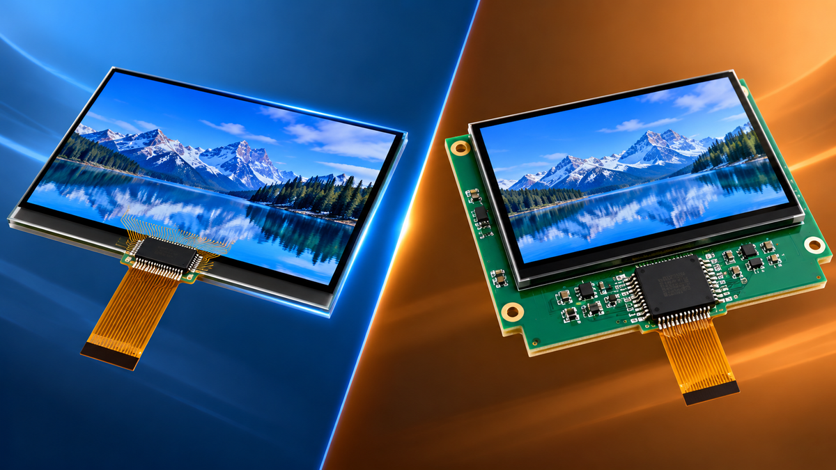
COG goes thinner in both directions: 6.0 mm against 13.6 mm on the same 128×64 dot count, and 400 lines along a glass edge at the finest strip pitch against 200 at the coarsest. COB is the one you can repair, because its strip is held by frame pressure instead of a bond: a field fix is four bench steps with no heat, and the PCB carries the driver, the connector and the passives. Pick COG when the enclosure leaves less than 6 mm, or when one glass edge has to carry more than 350 lines; pick COB when the unit gets opened in the field, or when the annual volume stays under 50,000 pieces and the design still moves.
A 2.93-inch 128×64 COB (Winstar WG12864A) measures 93.0 × 70.0 × 13.6 mm on the outside[1]. The 2.82-inch 128×64 COG (Winstar WO12864B) comes in two thickness versions, 12.1 mm and 6.0 mm[2]. The thin one saves 7.6 mm and lands at 44% of the COB.
The 7.6 mm splits into three parts adding up to 4.6 to 6.6 mm: the PCB, the zebra strip, and the solder joints on the back. The rest, 1 to 3 mm, is backlight and plastic frame.

Where the Thickness Differs
PCB 1.6 mm. Back-side driver circuit and solder joints 1 to 2 mm. Edge contact zone, where the zebra strip sits, 2 to 3 mm. Total 4.6 to 6.6 mm. Zebra strips come in heights from 0.5 mm to 19 mm, and 2 to 3 mm is what you’ll see most[3].
With 0.4 mm glass, the cell stack runs 1.1 to 1.3 mm. With 0.55 mm glass it’s 1.4 to 1.6 mm. A 0.3 mm gap, or 21% off. Even at 1.3 mm the glass only eats 22% of a 6.0 mm module. The other 4.7 to 4.9 mm is backlight and hardware, and since the cell spans only 0.5 mm across both substrate options, the 6.1 mm between the 12.1 mm and 6.0 mm versions sits in that pair, not in the glass.
Glass substrate thinning with hydrofluoric acid takes the pane down to 0.2 mm, even 0.1 mm, and it is priced by glass area. Same area, same price. Thinning won’t separate the two.
A third 128×64 module, this one on a 20-pin through-hole interface, is 8.9 mm deep at maximum and weighs 35.5 g (module drawing), which puts the same dot count at 13.6, 12.1, 8.9 and 6.0 mm across four builds.
An 89.7 × 49.8 × 1.6 mm FR-4 board works out to 7.15 cm³. Board thickness is a printed board design choice rather than a display parameter[4]. At 1.85 g/cm³ that’s about 13 g. The 0.4 mm double-glass stack of the same footprint weighs 8.9 g, so a COB build carries 13 g of board that a COG build does not.
| Item | COB structure | COG structure |
|---|---|---|
| Driver chip location | On the PCB, wire-bonded and sealed in black glue | On the glass edge, bonded with conductive film |
| PCB stack | 1.6 mm standard board, 89.7 × 49.8 mm, about 13 g | None, or one narrow flex tail |
| Glass-to-board connector | Zebra strip, 2 to 3 mm once compressed | None, chip sits on the glass |
| Glass cell thickness | 0.4 mm substrate gives 1.1 to 1.3 mm | Same glass, thinning can reach 0.2 mm substrate |
| 128×64 finished module | 13.6 mm, 2.93 inch | 6.0 mm or 12.1 mm, 2.82 inch |
| Where the savings come from | Thinner backlight and frame | No PCB, no connector |
Where Assembly Differs
The whole COG bonding sequence runs in one hot press at 190 to 210 °C: gold bumps on the chip, a 20 µm conductive film, ITO electrodes on the glass, all aligned in the same stroke[5]. The film runs only 6.7 times thicker than the 3 µm particles inside it. Adjacent traces sit 12 µm apart. Four particle diameters, no more. A fine-pitch version cuts the gap to 5 µm and leaves 1.7 diameters of slack.
The bond carries no solder, so it adds no lead either and needs no lead exemption under RoHS[6].
A 10 mm × 2 mm driver chip has 20 mm² of bump area. At 60 MPa that’s 1,200 N, about 122 kgf, or 6.1 kgf/mm². At 80 MPa it’s 163 kgf. So you’re piling 120 to 160 kg onto 0.4 to 0.7 mm glass, and alignment still has to hold within 3 µm.
The press tops out at 230 °C, and ITO glass holds its shape to a strain point around 510 °C, so heat uses only 45% of that span.
Once the press comes down on COG you get one answer: it works or it doesn’t. COB splits into three steps, wire bonding, black glue cure and frame press, and the first two can each be measured and sent back.
Winstar’s 128×64 COB brings the interface out on a single 18-pin row, plus two positions for the LED backlight[1]. The 20-pin module in the thickness section runs a 2.54 mm through-hole pitch, and board connectors at that pitch are stock parts, so the interface needs no custom part. Two rows is a different part number, WG12864A1.
The zebra strip compresses 10% at most, and the frame holds both rows of pads together by mechanical pressure alone.
Where Repairability Differs
The bench job is four steps, all at room temperature.
- Pull the frame off.
- Wipe the oxide off the zebra strip and the pads with anhydrous ethanol. The compressed contact is only as good as those two surfaces.
- Put it back and adjust the pressure bar. Target 0.2 mm of compression.
- Power it up and re-test.
When the strip goes flat, you swap it. Match the original height and the 140 or 240 layers-per-inch spec[7]. One part number, no ECN.
Of the four field failures, two clean up and two need parts. Bad zebra contact and oxidized pads come back after a wipe and a re-press. Dead driver channels and failed passives need swapping. Passives and connectors follow the board rework procedure, IPC-7711/7721, current edition D from January 2024[8]. The bare die is the exception. It’s wire-bonded to the board and sealed under black glue, so replacing it means re-bonding. Most repair shops outside the factory don’t have that machine.
COG has no bench path at all. The chip sits on ITO traces at the bond edge, where adjacent lines run 12 µm apart, or 5 µm on the fine-pitch version. Re-pressing means heating and peeling the whole stack, and the pull lands on those lines, which break. A zebra strip’s finest contact pitch is 250 µm, 21 to 50 times wider. A finished module also stacks the backlight and flex over the bond area, so you’d have to take two layers apart first. Industry practice is to swap the module and bill by the piece.
Contact Density Sets the Resolution Ceiling
Fujipoly wants at least two conductive layers under every contact.
| Series | Layer pitch | Layer density | Nominal contact pitch | Effective minimum spacing |
|---|---|---|---|---|
| 1002 | 0.1 mm | 240 per inch | 0.38 mm | 0.2 mm |
| 2004 | 0.18 mm | 140 per inch | 0.50 mm | 0.36 mm |
| 2005 | 0.05 mm | 500 per inch | 0.25 mm | 0.1 mm |
Divide 25.4 mm by 0.1 mm and you get 254 layers, while the vendor lists 240. That 14-layer difference is the vendor rounding to a round number, and the listed figures are the ones to design against.
At nominal pitch, 1 mm of edge fits at most 4 signal lines. On conductive film a 12 µm gap plus a 10 µm trace gives a 22 µm pitch, and the same 1 mm fits 45.
Take a 100 mm glass edge. At 0.25, 0.38 and 0.50 mm contact pitch, a zebra strip carries 400, 263 and 200 lines. Switch to a 22 µm film pitch and you get 4,545, or 11.4 times the 400.
The 89.7 mm outline on the 128×64 COG build used here fits 358 contacts at the finest strip pitch, which is 42 short of the 400 a full 100 mm edge carries. At 0.50 mm pitch the same 89.7 mm holds 179, so 192 lines will not go on one edge; they need 96 mm at that pitch, 73 mm at 0.38 mm, or 48 mm at 0.25 mm, which is 54% of the module width.
A 128×64 graphic module needs 128 SEG lines plus 64 COM lines, so 192 lines, or 48% of the 0.25 mm column. A 240×160 needs 240 plus 160, so 400. Exactly one standard 100 mm run.
The Winstar COB drives that matrix at 1/64 duty, so all 64 COM lines come out and none can be shared; the COG module linked above runs 1/65 to carry one indicator line, so 193. Either way the line count follows from the duty scheme, and it is the floor for the panel rather than a target.
KAIST draws the ultra-fine-pitch line below 30 µm. Their group wrapped conductive particles in nanofibers and reported 100% insulation at a 20 µm pitch, which is the condition a fine-pitch bond has to hold[9].
The Cost Crossover
COG needs a custom ITO electrode layout, so the photomask is a one-time spend, and that mask is where the price difference against a standard LCD module sits. COB skips the mask and runs on standard glass and standard boards. A pilot batch costs you one board’s tooling.
Glass is bought by the sheet. A 14-inch sheet is 355.6 mm square, or 126,451 mm². The 2.82-inch module outline is 89.7 × 49.8 mm, or 4,467 mm² per piece. Seven rows at 49.8 mm plus seven 1 mm cutting lanes come to 355.6 mm, exactly the sheet width with no edge left over, so production layouts run 3 columns by 6 rows: 18 pieces and 63.6%.
So order quantities jump in steps of 18. Ask for 19 and you need a second sheet. That second sheet carries a single piece, so it runs at 3.5% utilization.
Past 100,000 pieces a year with the design frozen, the material you save on the board and the zebra strip pays back the mask. Under 50,000 pieces with revisions still coming, COB’s tooling and turnaround win. Both thresholds are rules of thumb, order-of-magnitude only.
Swap the PCB from 1.6 mm to 0.8 mm and the module goes from 13.6 mm to 12.8 mm. Still 6.8 mm thicker than the thin COG.
Two Different Failure Paths
Carbon zebra strips top out at 100 °C and 5 mA per 1.03 mm² pad. Push past that and the strip ages faster. Contact resistance climbs as compression drops and the pads lose pressure. At 2.2 mm uncompressed height, every percentage point of compression ratio is 0.022 mm of travel.
On screen you see 1 or 2 segments drop out first, then whole blocks. When vibration loosens the pressure bar and screws, dropouts go from occasional to permanent.
COG fails open instead. Broken bonds, micro-cracks at the glass edge, corroded ITO traces. All three show up as missing segments in fixed positions, and no firmware tweak brings them back.
The module itself runs −20 to +70 °C, a 90 °C span. The zebra strip runs −40 to +100 °C, a 140 °C span. That gives 20 °C more at the bottom and 30 °C more at the top.
Visual inspection follows IEC 61747-20-2:2015, published in 2015 and covering both powered and unpowered states[10]. The matching Chinese blank detail spec is GB/T 18910.21-2024, effective 25 April 2024, identical to IEC 61747-2-1:2013[11]. The general specification above it is GB/T 18910.11-2024, effective 1 August 2024, which replaced GB/T 18910.1-2012[12].
Sinusoidal vibration per GB/T 2423.10-2019, shock per GB/T 2423.5-2019, combined temperature, humidity and vibration-shock per GB/T 2423.35-2019[13], and vibration time history plus sine beat per GB/T 2423.48-2018[14]. Vibration, shock and damp heat also sit in the IEC 60068 series as IEC 60068-2-6:2007[15], IEC 60068-2-27:2008[16] and IEC 60068-2-78:2025[17].
Pick by Project Conditions
- If nobody can open the unit in the field, and it never comes back for repair, COG’s swap-only rule costs you nothing, which is the situation sealed handheld and medical builds are in.
- Fixed cabinets that see heavy vibration and shock go COB. Mounting and screw loads go into the PCB and the frame, so the glass edge never carries them.
- Connectors and passives sitting next to the display point to COB. The board carries both part types for free, and driver board and adapter options cover the hosts that cannot take them.
- Density and service access in one design point to COF. The driver chip goes onto a flexible carrier, then the carrier gets pressed onto the glass. Thickness lands between COG and COB. The cost is a second press at the driver stage, so two yield loss points instead of one.
Five Files to Ask For Before Tooling
- Module mechanical drawing with glass thickness, overall thickness and tolerances. Three numbers, no approximations. A custom FPC tail and backlight spec belongs on the same drawing.
- Driver chip part number and bonding parameters: film spec, 190 to 230 °C, 60 to 80 MPa, 5 seconds. All four.
- Zebra strip pitch, layer count, height and compression ratio range. All four numbers.
- Standard numbers, both sets. Module body GB/T 18910.21-2024, and the environmental items should name which GB/T 2423 parts apply.
- Visual inspection criteria sheet, with defect types and accept counts that map to the tables in IEC 61747-20-2.
Two Things People Skip
Thinning the glass won’t thin the module. Going from 0.4 mm to 0.2 mm only drops the double-glass stack by 0.4 mm, and the backlight, the frame and the contact zone don’t move at all.
Don’t order a zebra strip by its compressed height. Work backwards from 2.0 mm compressed and you need 2.2 mm uncompressed.
How to Decide
Cross one of the two thresholds and the decision is made. The other one just becomes structural headroom. Cross both and COG is the only answer.
Send three numbers: the thickness your enclosure leaves, the signal lines you need along one glass edge, and your annual volume. You get back the COG or COB call against those numbers, the module outline drawing with glass and overall thickness tolerances, and the tooling cost at that volume.
Hinterlasse einen Kommentar
Diese Website ist durch hCaptcha geschützt und es gelten die allgemeinen Geschäftsbedingungen und Datenschutzbestimmungen von hCaptcha.