









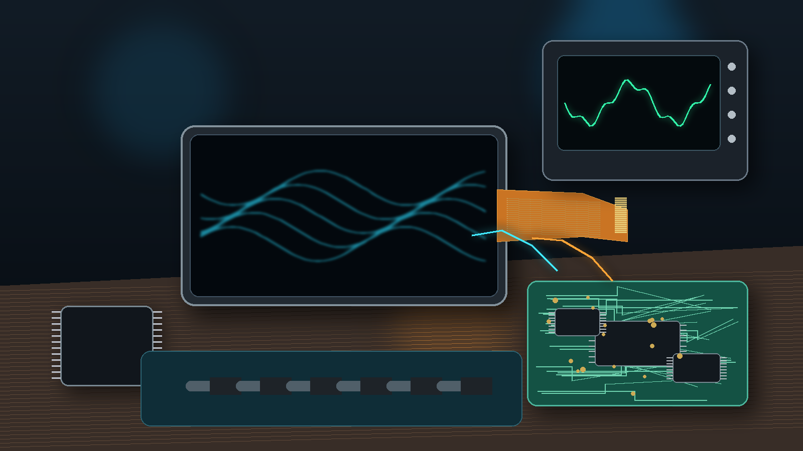
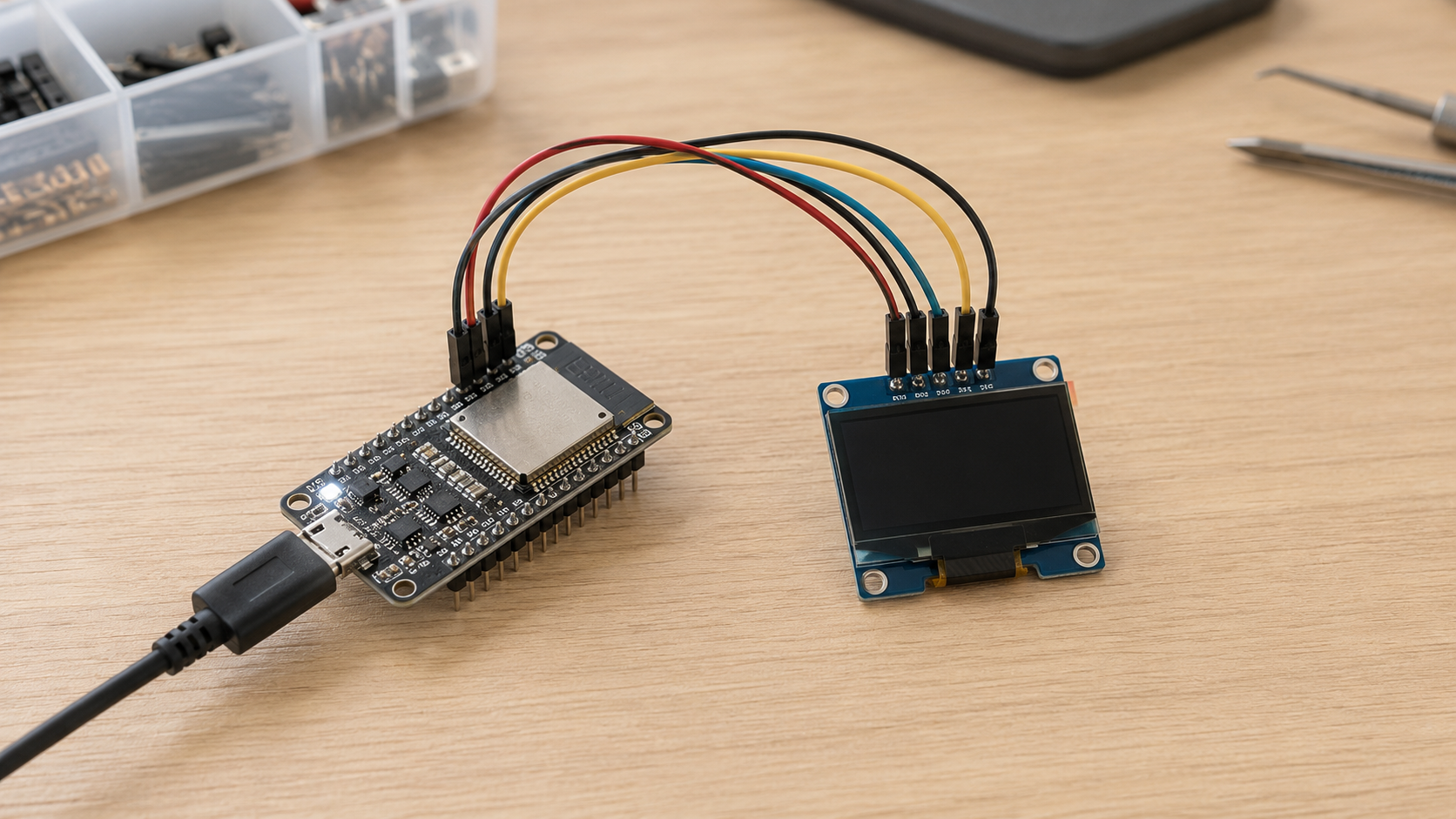
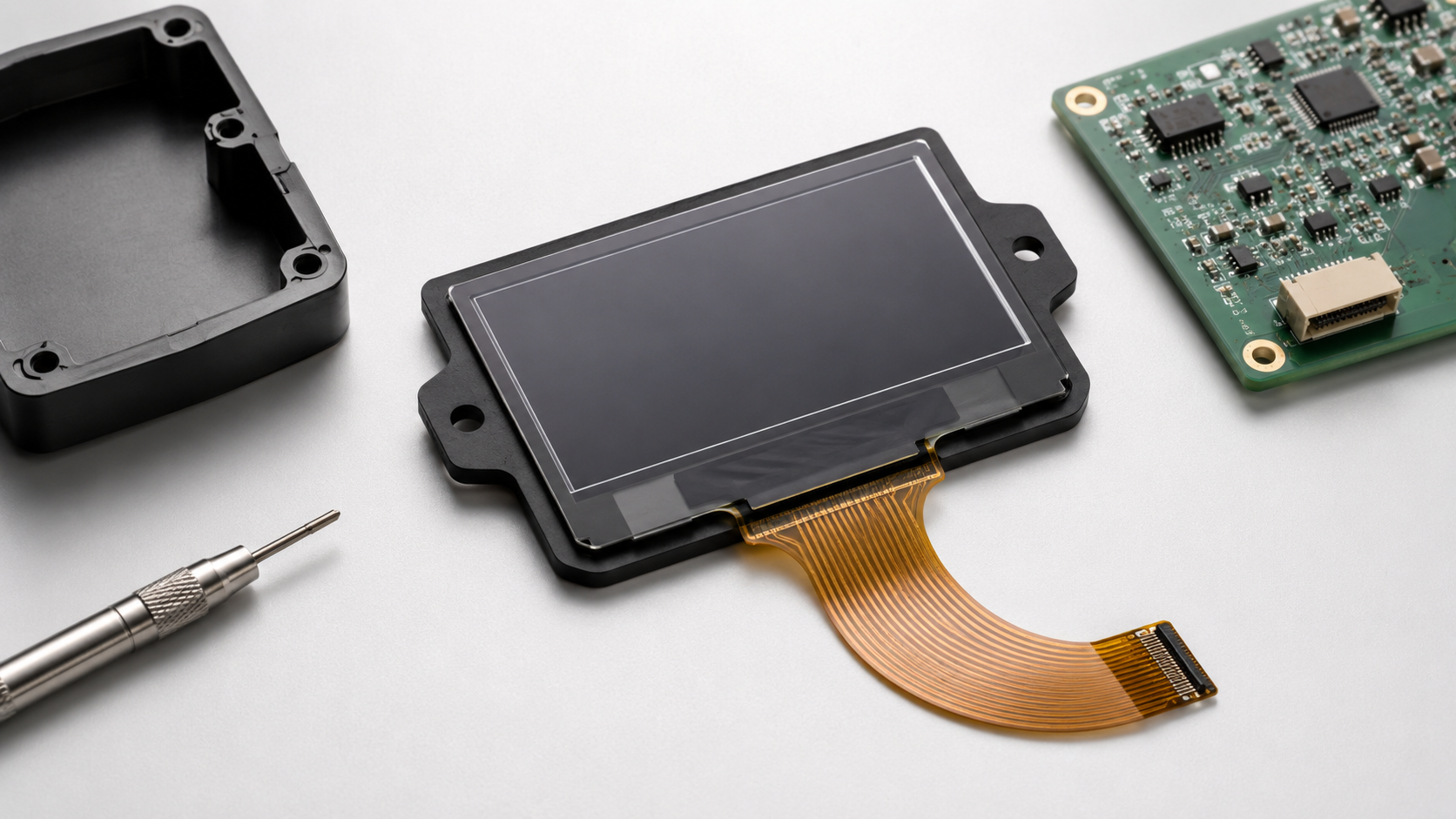
Yes, an obsolete graphic OLED module can often be replaced without changing the enclosure or host PCB. The replacement must keep the required outline, active-area position, connector, voltage levels and interface. Firmware must be updated when the new controller uses different commands, RAM addresses, pixel packing or startup timing. A custom FPC can reroute pins, but it cannot correct an unsafe voltage, two outputs connected together or an unsupported interface.
Can the Existing PCB Be Kept?
| Check | PCB Can Usually Remain | PCB Change Is Usually Needed |
|---|---|---|
| Logic voltage | The new controller accepts the host I/O levels | The host voltage exceeds the new input limit |
| Power rails | The required logic and OLED rails already exist | A new rail or larger power converter is required |
| Interface | The old SPI, I²C or parallel bus is supported | The new controller needs unavailable MCU pins |
| Connector | A custom FPC can reproduce the old connector position | The existing connector has too few pins |
| Pin functions | Signals can be safely rerouted inside the FPC | A host output is connected to a controller output |
| Firmware | The product firmware can be updated | Installed products cannot receive new firmware |
A separate adapter board keeps the product working but is not a direct module replacement. An adapter circuit built into the OLED module can provide drop-in operation when the outside dimensions, connector, voltage levels and commands remain unchanged.
When PCB changes are allowed, a standard model from the OLED display module range can reduce tooling and firmware work. A custom FPC is more useful when the enclosure, display window and host connector are fixed.
What Must Be Taken from the Old Module?
Collect the following before selecting a replacement:
- Old module and controller part numbers
- Module, glass and FPC drawings
- Host-board schematic
- Working firmware and initialization commands
- Resolution, color and grayscale format
- Active-area size and position
- Glass outline and total module thickness
- FPC length, width, pin count and pitch
- FPC contact side and stiffener thickness
- Connector manufacturer and exact part number
- Logic voltage and OLED driving voltage
- Interface type and mode-pin settings
- Operating and storage temperatures
- Annual demand and remaining product life
Inspect the real host PCB instead of relying only on the display datasheet. Record pull-up resistors, pull-down resistors, level translators, reset circuits, series resistors and unused pins tied to power or ground.
Use an oscilloscope or logic analyzer to capture:
- Logic-supply rise
- OLED-supply rise
- RESET pulse width
- Time from valid power to the first command
- SPI, I²C or parallel-bus timing
- Charge-pump or OLED-rail enable time
- Display-on command
- Peak startup current
Keep one working old module as a golden sample. Record its lot number, firmware version, startup waveform, all-pixels-on current and normal-screen current. Use the same sample when comparing brightness, image position and startup behavior.
Buy Remaining Stock or Redesign?
Identify which part is being discontinued:
| EOL Item | Likely Work |
|---|---|
| Controller IC | New controller, FPC routing, external parts and firmware |
| OLED glass | New active area, pixel pitch, bonding pads or optical limits |
| FPC or connector | New tail drawing, stiffener, contact finish and mating test |
| Complete module | New supplier, production process, test fixture and qualification |
A product change notice may cover a new wafer source, die revision, production site, FPC supplier or bonding material without ending production. Samples are still required when the change can affect dimensions, voltage, timing, image quality or reliability.
Texas Instruments states that its standard product-withdrawal process normally provides 12 months for the last order and another six months for final delivery, although accelerated cases can occur. This is one supplier’s policy, not a universal controller-industry period.[1]
Use this calculation for a lifetime buy:
Required order = (remaining production + service stock + test samples) ÷ (1 − expected loss rate)
Example:
- Remaining production: 8,000 modules
- Service stock: 500 modules
- Qualification and retained samples: 120 modules
- Expected assembly loss: 2%
Required order = 8,620 ÷ 0.98 = 8,795.9
The order must therefore include at least 8,796 modules before adding any forecast reserve. The loss rate and reserve must come from real production data, not a copied industry percentage.
Which Controller Can Actually Replace It?
Three 128 × 64 modules can use different controllers. DisplayModule lists a 0.96-inch SSD1306 module, a 1.3-inch SH1106 module and a 1.29-inch SSD1315 module. Their visible resolution is the same, but their RAM layout, commands, interfaces and power settings are not automatically interchangeable.
SSD1306 is officially described as a controller with 128 segment outputs and 64 common outputs for common-cathode OLED panels.[2]
| Controller Check | Required Information |
|---|---|
| Panel type | Monochrome, grayscale or RGB |
| Electrode structure | Common cathode or common anode |
| Output count | Required segment and common channels |
| RAM | Width, height, addressing mode and pixel format |
| Logic voltage | Minimum, maximum and input thresholds |
| OLED drive | Panel voltage, current range and pre-charge settings |
| Interface | SPI, I²C, 6800 or 8080 support |
| Package | COG bare die, COF or packaged IC |
| Lifecycle | Production status, die revision and PCN policy |
A color OLED may need separate output channels for red, green and blue subpixels. Controller suppliers therefore list monochrome formats such as 128 × 64 and color formats such as 96RGB × 64 or 160RGB × 128.[3]
For chip-on-glass production, also compare the die dimensions, bump pitch, glass-pad layout, ACF material, bonding temperature, bonding pressure and alignment tolerance. A controller can support the required commands but still be impossible to bond to the existing glass.
Which Pin Changes Stop the Project?
Complete one row for every host-connector pin:
| Host Pin | Old Signal | New Signal | Voltage | Direction | Action |
|---|---|---|---|---|---|
| [Pin] | [Old function] | [New function] | [Voltage domain] | [Input / Output / Power] | [Direct / Reroute / Isolate / PCB change] |
Record the reset state, internal pull resistor, required external resistor, maximum voltage and host state during startup for every pin.
Stop the design when any of these conditions appears:
- An old NC pin becomes a power pin.
- An old power pin becomes a charge-pump capacitor pin.
- An old input becomes an output.
- A ground pin becomes an analog reference.
- A 3.3 V host signal exceeds the new controller input limit.
- A factory test pin is connected to the host.
- An interface-selection pin is left floating.
If the host and display both drive the same line, output contention can cause excess current or permanent damage even when both devices use the same nominal voltage.
Do not assume that NC always means “not internally connected.” It can also mean reserved, factory use or do not connect. Follow the new controller document.
Will the FPC Fit the Existing Connector?
Calculate the contact-center span with:
Contact-center span = (pin count − 1) × pitch
| Pin Count | Pitch | First-to-Last Contact Center |
|---|---|---|
| 20 pins | 0.5 mm | 9.5 mm |
| 30 pins | 0.5 mm | 14.5 mm |
| 40 pins | 0.5 mm | 19.5 mm |
| 30 pins | 0.3 mm | 8.7 mm |
The contact-center span is not the finished FPC width. Add the contact width, edge clearance and manufacturing tolerance on both sides.
Check the exact connector part number for:
- Top-contact or bottom-contact design
- FPC nominal thickness and tolerance
- Stiffener thickness
- Exposed contact length
- Contact plating
- Insertion depth
- Tail width
- Pin 1 position
- Locking method
An FPC may enter the connector but still make poor contact if it is too thin, too thick or has the wrong exposed-contact length.
Use one assembled-view drawing showing the OLED viewing side, host PCB, contact side, connector opening, pin 1 and insertion direction. This avoids a mirrored pinout caused by comparing a front view with a rear view.
Where Will the FPC Crack?
Keep vias, sharp trace-width changes and unsupported copper away from:
- The glass edge
- The glass-to-FPC bonding area
- The stiffener edge
- The connector entry
- The normal fold line
Use wider traces for OLED power and ground than for low-current control lines. Fast clock and data traces need a short return path. Check the clock waveform at the module connector before adding a series resistor or reducing the bus speed.
IPC-2223E covers flexible and rigid-flex board design, including bend areas, shielding, ground and power planes, stiffeners and strain relief.[4]
IPC-6013E covers qualification and performance requirements for flexible boards and separates flex during installation from continuous flexing for a specified number of cycles.[5]
Do not write only “IPC compliant” in the drawing. State:
- FPC construction
- Required performance class
- Installation or repeated-flex use
- Required bend test
- Continuity and short-circuit test
- Finished thickness tolerance
- Contact-plating requirement
Will the Power Rails Start the New Module?
List every rail and measure it at the module connector. Do not treat VDD, VCI, VCC, VPP, ELVDD and ELVSS as interchangeable names.
| Measurement | What to Record |
|---|---|
| Logic rail | Minimum voltage, rise time and ripple |
| OLED rail | Startup voltage, loaded voltage and discharge time |
| RESET | Active level, pulse width and release time |
| Startup current | Peak value and duration |
| Running current | Current for each test image |
| Sleep current | Module current and any back-powering current |
OLED current changes with the number and color of lit pixels. The PMOLED power-consumption guide explains why resolution alone cannot predict module current.
| Test Pattern | Logic Current | OLED-Rail Current | Peak Current | Rail Drop |
|---|---|---|---|---|
| All pixels off | [Measure] | [Measure] | [Measure] | [Measure] |
| 25% pixels on | [Measure] | [Measure] | [Measure] | [Measure] |
| 50% pixels on | [Measure] | [Measure] | [Measure] | [Measure] |
| All pixels on | [Measure] | [Measure] | [Measure] | [Measure] |
| Normal user screen | [Measure] | [Measure] | [Measure] | [Measure] |
For color OLEDs, add solid red, green, blue and white patterns. Repeat startup at minimum voltage, low temperature, slow supply rise and after a short power interruption.
Can the Interface Refresh the Screen Fast Enough?
The interface name is not enough. Check voltage, clock mode, timing and data framing.
| Interface | Required Checks |
|---|---|
| SPI | Three-wire or four-wire mode, clock polarity, phase, bit order, CS timing, D/C timing and verified clock rate |
| I²C | 7-bit address, control byte, pull-up voltage, resistance, bus speed, ACK response and bus recovery |
| 6800 parallel | Enable timing, read/write polarity, register select and data setup and hold |
| 8080 parallel | Write strobe, read strobe, data/command selection and data setup and hold |
The NXP I²C specification defines Standard-mode at up to 100 kbit/s, Fast-mode at up to 400 kbit/s and Fast-mode Plus at up to 1 Mbit/s. The OLED controller may support only some of these modes, so the controller timing table remains the final limit.[6]
A 128 × 64 monochrome framebuffer contains 1,024 bytes. The following values are theoretical payload times and do not include addressing, commands, start and stop conditions or software delays:
| Interface Speed | Minimum Time for 1,024 Bytes |
|---|---|
| 100 kbit/s I²C | 92.2 ms |
| 400 kbit/s I²C | 23.0 ms |
| 1 Mbit/s I²C | 9.2 ms |
| 8 Mbit/s SPI | 1.02 ms |
| 16 Mbit/s SPI | 0.51 ms |
Not every controller supports 1 Mbit/s I²C or 16 Mbit/s SPI. The calculation only shows the data-rate difference. The SPI and I²C comparison can be used when deciding between fewer MCU pins and faster screen updates.
Does the MCU Have Enough RAM?
Use:
Framebuffer size = width × height × bits per pixel ÷ 8
| Resolution and Format | Pixels | One Frame | Raw Data at 60 fps |
|---|---|---|---|
| 128 × 64, 1-bit monochrome | 8,192 | 1,024 bytes | 61,440 bytes/s |
| 128 × 64, 4-bit grayscale | 8,192 | 4,096 bytes | 245,760 bytes/s |
| 128 × 64, RGB565 | 8,192 | 16,384 bytes | 983,040 bytes/s |
| 160 × 128, RGB565 | 20,480 | 40,960 bytes | 2,457,600 bytes/s |
Changing a 128 × 64 display from 1-bit monochrome to 4-bit grayscale increases framebuffer RAM from 1,024 bytes to 4,096 bytes. Moving to RGB565 at the same resolution increases it to 16,384 bytes.
If the MCU uses double buffering, multiply the frame size by two. Add memory for fonts, icons, communication buffers and the application before deciding that the MCU has enough RAM.
Where Will the Image Shift or Mirror?
Check these controller-RAM details:
- RAM width and height
- Visible column start
- Visible row start
- Page, horizontal or vertical addressing
- Column and row increment direction
- Segment and common remap
- MSB-first or LSB-first packing
- High-nibble or low-nibble order
- RGB or BGR order
- High-byte or low-byte first
Example: the visible panel uses controller columns 2–129, but the firmware writes columns 0–127. The image shifts by two columns. On a 128-column display, that equals a 1.56% horizontal shift.
Use these patterns to find mapping errors:
- One-pixel border
- Single pixels in all four corners
- Alternating vertical lines
- Alternating horizontal lines
- Solid red, green and blue for color OLEDs
A logo is not a good mapping test because it may not use the outer rows and columns.
Which Firmware Files Must Change?
Separate the code into three files or layers:
- Bus layer: SPI, I²C or parallel transfer, reset, chip select, D/C, delays and timeouts
- Controller layer: initialization, address windows, orientation, drive settings, sleep and display control
- Graphics layer: framebuffer, fonts, icons, menus, lines and bitmaps
The graphics layer should not contain controller register values.
typedef enum
{
    OLED_OK = 0,
    OLED_TIMEOUT,
    OLED_INVALID_PARAMETER,
    OLED_NOT_INITIALIZED
} oled_status_t;

oled_status_t oled_reset(void);
oled_status_t oled_write_command(uint8_t command);
oled_status_t oled_write_data(const uint8_t *data, size_t length);
oled_status_t oled_set_window(uint16_t x0, uint16_t y0,
                              uint16_t x1, uint16_t y1);
oled_status_t oled_sleep(void);
oled_status_t oled_wake(void);
Create an old-to-new command table for:
| Function | Old Controller | New Controller | Test Result |
|---|---|---|---|
| Display off/on | [Command and parameters] | [Command and parameters] | [Pass / Fail] |
| Address mode | [Value] | [Value] | [Pass / Fail] |
| Column and row window | [Range] | [Range] | [Pass / Fail] |
| Orientation | [Remap setting] | [Remap setting] | [Pass / Fail] |
| Drive current | [Value] | [Value] | [Pass / Fail] |
| Sleep and wake | [Sequence] | [Sequence] | [Pass / Fail] |
Define recovery from bus timeout, interrupted initialization, MCU brownout and display reset. A display that wakes but keeps the wrong RAM window can acknowledge new data while showing nothing useful.
What Must Be in the Startup Table?
There is no universal OLED startup order. Record the exact value and delay for each step:
| Startup Item | Approved Value | Measured Result |
|---|---|---|
| Mode pins valid | [Time before reset release] | [Measured] |
| Logic rail valid | [Voltage and rise time] | [Measured] |
| RESET active time | [Minimum time] | [Measured] |
| Delay before first command | [Time] | [Measured] |
| OLED rail or charge pump enabled | [Sequence point] | [Measured] |
| RAM cleared | [Address range] | [Confirmed] |
| Display on | [Command and time] | [Measured] |
Keep display output off until valid image data has been written. Turning the panel on before clearing RAM can show random pixels or a bright startup flash.
Test shutdown and wake with the same detail. The I²C OLED sleep-cycle guide shows why power, bus and controller state must all be restored after repeated sleep cycles.
What Must Be Measured on the First Samples?
| Test | Test Condition | Recorded Result |
|---|---|---|
| Cold startup | Minimum operating temperature and minimum voltage | Startup time and pass/fail |
| Warm restart | Display already at operating temperature | Startup time and visible flash |
| Rapid power cycle | Short off-time followed by restart | Failed starts and rail discharge |
| Full-screen write | All pixels on or full-white pattern | Current, rail drop and image result |
| Sleep and wake | Repeated cycles | Wake failures and sleep current |
| RAM mapping | Border, corner pixels and line patterns | Offset, mirror and missing pixels |
| Optical comparison | Same voltage, image, temperature and angle | Luminance, uniformity and color |
| FPC fit | Final connector and enclosure | Insertion, contact and bend condition |
IEC 62341-6-1:2025 defines standard conditions and methods for measuring optical and electro-optical OLED display parameters.[7]
Use the same voltage, test image, temperature, warm-up time, viewing angle and measuring position for the old and new modules.
Static icons, borders and status bars should be checked for image retention at the real brightness, temperature and duty cycle. IEC 62341-5-3:2019 specifies methods for measuring OLED image sticking and module lifetime.[8]
After temperature, humidity, vibration, shock or FPC-bend testing, repeat startup, current, image, connector and continuity checks. A module should not pass only because the glass remains unbroken.
What Failed When the Screen Is Blank?
| Symptom | First Measurement | Likely Cause | Corrective Action |
|---|---|---|---|
| Blank screen | Logic rail, OLED rail and RESET | Wrong startup order or missing display-on command | Correct the power and initialization sequence |
| Shifted image | One-pixel border | Wrong column or row offset | Change the address window |
| Mirrored image | Corner-pixel pattern | Wrong segment or common remap | Change orientation commands |
| Random pixels at startup | Display-on timing | Output enabled before RAM is cleared | Write a valid frame before display-on |
| Dim image | OLED rail and drive-current setting | Wrong voltage, IREF or pre-charge | Use settings approved for the glass |
| Reset on a bright image | Peak current and rail drop | Power converter or charge pump is too weak | Increase power capacity or lower the approved drive |
| Works only at low SPI speed | Clock waveform at the connector | Ringing, slow edge or timing violation | Improve routing, add damping or reduce speed |
| I²C bus remains low | SDA and SCL after reset | Interrupted transfer or back-powering | Add bus recovery and correct GPIO states |
| Wrong colors | Solid red, green and blue screens | RGB/BGR or byte-order mismatch | Correct the pixel format |
| Intermittent connector contact | FPC thickness and insertion depth | Incorrect connector mating dimensions | Revise the FPC or connector specification |
| High sleep current | OLED rail and host pins | Charge pump remains on or signals back-power the module | Correct shutdown commands and GPIO states |
What Must Be Frozen Before Mass Production?
Use one module part number for one approved combination of:
- OLED glass
- Controller and die revision
- FPC revision
- Connector
- ACF material
- External capacitors and resistors
- Initialization table
- Firmware version
- Production test program
Record the glass lot, controller lot, FPC revision, ACF lot, bonding line, firmware checksum, test-program revision and production date for every lot.
The approved release file should contain:
- Mechanical drawing
- FPC drawing
- Connector mating view
- Pin map
- Old-to-new controller comparison
- Power and startup table
- Initialization code
- Functional test report
- Electrical and optical measurements
- Reliability results
- Old and new golden-sample numbers
The supply agreement must state which changes only need notice and which require new samples. Controller die, OLED material, glass mask, FPC material, connector, ACF, critical capacitors, bonding process and production site should not change without documented review.
Finally
Release the replacement only when the drawing, FPC, pin map, voltage limits, interface timing and firmware refer to the same module revision. A 128 × 64 frame needs 1,024 bytes in 1-bit monochrome, 4,096 bytes at 4-bit grayscale and 16,384 bytes in RGB565. A 30-pin FPC at 0.5 mm pitch has a 14.5 mm contact-center span before edge margins are added. Test borders, corner pixels, all-on current, minimum-voltage startup, rapid power cycling and sleep recovery. Keep one old golden sample and one approved replacement, then record the controller lot, FPC revision, firmware checksum and test-program version for each production lot.
Hinterlasse einen Kommentar
Diese Website ist durch hCaptcha geschützt und es gelten die allgemeinen Geschäftsbedingungen und Datenschutzbestimmungen von hCaptcha.