


How to Interface a TFT LCD Module with Arduino and ESP32 | SPI, Parallel, and Display Library Setup
TFT LCD display modules are widely used in embedded projects, including sensor dashboards, industrial control panels, handheld instruments, smart home interfaces, data loggers, and IoT devices.
A TFT module may look simple from the outside, but successful integration depends on the display controller, interface type, logic voltage, wiring quality, MCU memory, software library, and touch-controller support.
| Project factor | What to check before wiring | Why it matters |
|---|---|---|
| Controller IC | Check whether the module uses ST7735, ST7789, ILI9341, ILI9488, GC9A01, or another controller. | Different controllers use different initialization commands, color order settings, and library configurations. |
| Logic voltage | Confirm whether the display logic is 3.3 V, 5 V tolerant, or requires level shifting. | Voltage mismatch is a common cause of damaged TFT modules. |
| Resolution | Check the pixel size and calculate frame memory early. | Higher resolution increases bandwidth and RAM demand. |
| Interface pinout | Identify SPI, 8-bit parallel, 16-bit parallel, RGB, touch, SD card, reset, and backlight pins. | Wrong pin mapping often causes white screens, garbled screens, or no response. |
| Library support | Confirm that Arduino, ESP32, TFT_eSPI, LVGL, or Adafruit GFX supports the selected controller and MCU. | Library support affects setup difficulty, speed, touch integration, and long-term maintainability. |
For Arduino and ESP32 projects, the most common TFT LCD connection methods are SPI, 8-bit parallel, 16-bit parallel, and RGB-style interfaces.
- Small displays such as 1.44-inch, 1.8-inch, 2.4-inch, and 2.8-inch modules often use SPI.
- Larger 3.5-inch, 4.3-inch, 5-inch, and 7-inch modules may use parallel, RGB, or dedicated display-controller interfaces when higher refresh rates are needed.
Before wiring a TFT LCD module, check five things first: the controller IC, the required logic voltage, the display resolution, the interface pinout, and the library support for your MCU.
A 1.8-inch ST7735 display, a 2.8-inch ILI9341 display, and a 3.5-inch ILI9488 display may all be called TFT LCD modules.
However, their initialization commands, memory demand, and refresh performance can be very different[1].

Hardware Connection
4-Wire SPI Connection
For many TFT LCD display modules, “4-wire SPI” usually refers to the display-side control signals SCLK, MOSI, CS, and D/C.
The MISO line is optional for many TFT-only applications because the display is often written to rather than read back.
- MISO may be needed if the module supports display readback.
- MISO may be needed if the module includes a microSD card socket.
- MISO may be needed if the module shares the SPI bus with a touch controller[2].
| Board | Typical hardware SPI pins | Common notes |
|---|---|---|
| Arduino Uno / Nano | D13 for SCK, D11 for MOSI, and D12 for MISO | CS, D/C, and RST can usually be assigned to ordinary GPIO pins, with D10, D9, and D8 commonly used in examples. |
| Arduino Mega 2560 | Hardware SPI pins are on the ICSP header and also mapped to board-specific pins. | The exact wiring should follow the board documentation and the display library example[3]. |
| ESP32 / ESP32-S3 | SPI pins can often be routed through the GPIO matrix. | Not every pin is equally suitable because some pins are used during boot, connected to flash or PSRAM, or may affect startup mode[4]. |
For stable TFT operation on ESP32 and ESP32-S3, choose pins recommended by the board vendor.
Keep the wiring short, and use a common ground between the display and MCU[4].
The ILI9341 controller supports multiple interface types, including parallel MCU interfaces, RGB interfaces, and 3-line or 4-line serial peripheral interfaces.
In practical Arduino and ESP32 projects, most SPI libraries use 4-wire 8-bit SPI with a separate D/C pin because it is easier to support across common MCUs.
Some controllers also support 3-wire 9-bit serial mode, but this mode is less commonly used in Arduino examples because the command/data bit must be packed into the serial transfer[5].
| Display size / frame | Color format | Frame size | Ideal transfer result |
|---|---|---|---|
| 320×480 | 16-bit RGB565 | 320 × 480 × 2 = 307,200 bytes | At an ideal 40 MHz SPI clock, the raw transfer time is about 61 ms per full frame. |
SPI bandwidth should be calculated before choosing a display resolution.
A 320×480 display using 16-bit RGB565 color needs 320 × 480 × 2 = 307,200 bytes for one full frame.
At an ideal 40 MHz SPI clock, the raw transfer time is about 61 ms per full frame before command overhead, software overhead, and bus gaps are included.
This means full-screen 60 fps refresh is not realistic over ordinary 4-wire SPI at 320×480.
However, partial redraws, sprites, DMA transfers, and dirty-area rendering can still make an SPI display feel smooth in many real applications[4].
For stable SPI wiring, keep SCLK and MOSI short, avoid long parallel runs between fast signal wires, and place a 0.1 μF ceramic capacitor close to the display power pins.
For modules with larger backlights, adding a 4.7 μF to 10 μF bulk capacitor near the module can help reduce startup instability.
- The CS pin should be held at the display logic high level during power-up until initialization begins.
- Do not pull a 3.3 V-only display input above its allowed voltage[5].
When multiple SPI devices share one bus, each device needs its own CS line.
- Only one CS line should be active at a time.
- If an SD card, touch controller, sensor, and TFT controller share the same SPI bus, use SPI transactions or another bus-locking method.
- This helps each device use the correct clock speed, bit order, and SPI mode[6].
8-Bit and 16-Bit Parallel
Parallel interfaces are used when a project needs faster full-screen updates than SPI can provide.
Common MCU-style TFT interfaces include 8080 and 6800 timing.
| Interface | Data lines | Control lines | Typical use |
|---|---|---|---|
| 8-bit parallel | 8 data lines | WR, RD, CS, D/C, and RST | Faster full-screen updates than SPI, but uses many GPIO pins. |
| 16-bit parallel | 16 data lines | WR, RD, CS, D/C, and RST | Higher bandwidth than 8-bit parallel, but requires even more pins[7]. |
Arduino Uno can theoretically drive some 8-bit parallel displays by reusing analog pins as digital I/O.
However, this leaves little room for buttons, sensors, serial interfaces, or other peripherals.
Arduino Mega 2560 is more suitable for 8-bit parallel experiments because it has 54 digital I/O pins and 16 analog input pins.
However, the Mega 2560 has only 8 KB of SRAM, so it cannot hold a full frame buffer for a 320×480 RGB565 display[8].
| Interface example | Theoretical transfer rate | 320×480 RGB565 full-frame result | Reality check |
|---|---|---|---|
| 4-wire SPI at 10 MHz | 10 Mbit/s | Roughly 4 full frames per second before overhead | Not suitable for constant high-resolution full-screen refresh. |
| 8-bit parallel at 10 MHz | About 10 MB/s | Roughly 32 full frames per second before overhead | Actual performance depends on GPIO speed, library implementation, and display timing. |
| 16-bit parallel at 10 MHz | About 20 MB/s | Roughly 65 full frames per second before overhead | Actual performance is still lower than the theoretical value. |
The bandwidth difference between SPI and parallel interfaces should be calculated from frame size, bus width, and clock rate.
A 320×480 RGB565 frame is 307,200 bytes.
At a theoretical 10 MHz clock, 4-wire SPI transfers about 10 Mbit/s, which is roughly 4 full frames per second before overhead.
An 8-bit parallel bus at 10 MHz transfers about 10 MB/s, which is roughly 32 full frames per second before overhead.
A 16-bit parallel bus at 10 MHz transfers about 20 MB/s, which is roughly 65 full frames per second before overhead.
Actual performance is lower than the theoretical number because of command setup time, GPIO access time, memory copy overhead, DMA limits, library implementation, and the timing limits of the display controller.
Claims such as “SPI 10 MHz can refresh a 320×480 RGB565 screen at 16 fps” or “8-bit parallel 10 MHz can refresh it at 130 fps” are not realistic.
The same screen size at 40 MHz SPI is closer to about 16 fps in ideal raw-transfer terms, not 10 MHz SPI.
For parallel TFT wiring, keep data lines short and route them with a consistent ground reference.
Length matching within a few centimeters is usually acceptable for low-speed prototypes, but faster designs should follow the timing requirements in the display controller datasheet.
Small series resistors, often in the 22 Ω to 47 Ω range, can help reduce ringing on long or sharp-edged signal lines.
The value should be verified on the actual PCB or prototype[5].
For 4.3-inch, 5-inch, and 7-inch TFT LCD modules, a 32-bit MCU with DMA and sufficient RAM is usually more practical than an 8-bit Arduino board.
If the display requires a full frame buffer, calculate the memory requirement early.
| Resolution | Color format | One full frame | Double buffering |
|---|---|---|---|
| 800×480 | RGB565 | 800 × 480 × 2 = 768,000 bytes | About 1.5 MB before fonts, images, GUI objects, stacks, and application data are counted. |
Level Matching: 3.3V vs 5V
Voltage-level mismatch is one of the most common causes of damaged TFT modules.
Many TFT display controllers use 3.3 V or lower logic domains, while Arduino Uno, Nano, and Mega boards output 5 V logic.
A bare 3.3 V display input should not be driven directly from a 5 V GPIO unless the module documentation clearly states that the board includes level shifting or 5 V-tolerant inputs[9].
| Signal type | Common direction | Level-matching note |
|---|---|---|
| SCK, MOSI, CS, D/C, RST | MCU output to TFT input | For a 5 V Arduino driving a 3.3 V TFT module, level shifting is needed. |
| MISO / readback lines | TFT, SD card, or touch controller output to MCU input | A 3.3 V output is often recognized as logic high by many 5 V AVR inputs, but this should be checked against the actual MCU datasheet and board design. |
| Backlight | Power path, not logic path | The backlight circuit is separate from logic-level shifting. |
For a 5 V Arduino driving a 3.3 V TFT module, a proper logic-level shifter or fast unidirectional buffer is the safest general solution.
A resistor divider can work for low-speed one-way signals, but at high SPI speeds the added RC delay can round the waveform edges and reduce timing margin.
If the project must avoid external level-shifting parts, choosing a native 3.3 V TFT display module and a 3.3 V MCU is usually simpler.
Readback lines need separate consideration.
For bidirectional buses or mixed-voltage systems, use a bidirectional level shifter designed for the required bus speed and signal type[9].
Some TFT modules include a backlight resistor or constant-current driver, while bare panels may expose LED+ and LED- directly.
- Do not assume LED+ can be connected to 5 V.
- Check the module documentation.
- Use a current-limiting resistor or constant-current driver when required.
- Confirm that the backlight current is within the rating of the MCU board’s regulator[2].
Software Library Selection
TFT_eSPI Library Configuration
TFT_eSPI by Bodmer is a popular Arduino-compatible graphics library for TFT displays.
It is targeted mainly at 32-bit processors and has processor-specific optimizations for platforms such as ESP32, ESP8266, RP2040, and STM32.
It supports many common TFT controllers, including ILI9341, ST7735, ST7789, ILI9486, ILI9488, GC9A01, and others, depending on the selected setup and target board[7].
| Configuration item | What to check |
|---|---|
| Display driver | Confirm the correct controller, such as ILI9341, ST7735, ST7789, ILI9488, or GC9A01. |
| Resolution | Check the screen width and height before uploading code. |
| SPI pins | Check SCLK, MOSI, MISO, CS, D/C, and RST against the selected board. |
| Touch pins | Check whether the touch controller shares SPI or uses another bus. |
| Fonts and optional features | Enable only the fonts and features needed by the project. |
The configuration method is different from many beginner Arduino examples.
Instead of always passing pin numbers in the sketch, TFT_eSPI is usually configured through User_Setup.h or through a selected file inside the User_Setups folder.
This approach allows the compiler to optimize pin access, but it also means the display driver, resolution, SPI pins, touch pins, fonts, and optional features must be checked before uploading code[10].
For PlatformIO projects, configuration can also be handled through build flags in platformio.ini.
This is useful when one codebase needs to support several boards or display modules.
Keep the working display setup under version control, otherwise a library update or reinstall may overwrite a manually edited configuration file[11].
On ESP32-S3, PSRAM availability depends on the exact module and board.
- Some ESP32-S3 boards have no PSRAM.
- Some ESP32-S3 boards have 2 MB PSRAM.
- Other ESP32-S3 boards have 8 MB or more.
Before enabling large sprites, LVGL buffers, or full-screen frame buffers, confirm the board’s PSRAM setting in the Arduino IDE or build configuration.
Espressif’s Arduino-ESP32 documentation specifically notes that board characteristics such as flash size, SoC variant, and PSRAM should be checked for the selected board[12].
TFT_eSPI can improve performance through hardware SPI, processor-specific optimizations, DMA support on supported targets, and off-screen sprites.
However, full-screen double or triple buffering is not a universal feature that works automatically on every board.
It depends on the display size, color depth, PSRAM capacity, DMA support, and application design.
For many Arduino and ESP32 interfaces, partial redraws and sprites are more realistic than storing multiple full frames[13].
Getting Started with LVGL
LVGL is an open-source embedded graphics library for building GUI interfaces on MCUs and MPUs.
It provides widgets such as buttons, labels, sliders, charts, lists, menus, images, and containers.
For projects that need a structured user interface rather than simple text and shapes, LVGL is often a better long-term choice than drawing every element manually[14].
LVGL can run on resource-constrained MCUs, but the real memory requirement depends on resolution, color depth, enabled widgets, fonts, image assets, draw-buffer size, and rendering mode.
LVGL’s official requirements distinguish between very small minimum components and recommended practical settings.
For display projects, draw-buffer memory should be calculated carefully.
LVGL recommends a partial buffer of at least about one-tenth of the display size for partial rendering in many cases[15].
| Screen size | Full-frame RGB565 size | About one-tenth draw buffer | Memory note |
|---|---|---|---|
| 320×240 | 153,600 bytes | About 15 KB | Additional fonts, images, themes, states, stacks, and application logic also consume memory. |
| 480×320 | 307,200 bytes | About 30 KB | Full-frame direct rendering or double buffering needs much more memory. |
If full-frame direct rendering or double buffering is used, memory demand becomes much higher.
Fonts, images, themes, object states, stacks, and application logic also consume RAM and flash[16].
Porting LVGL requires a display flush callback.
LVGL renders into a buffer, and the flush callback moves the rendered pixels from the draw buffer to the display hardware.
The transfer may use SPI, parallel, RGB, DMA, or another interface depending on the board and display module[17].
If touch, buttons, encoders, or keypads are used, LVGL also needs an input-device read callback.
The input device reports the current touch point, key state, encoder movement, or button state to LVGL.
For touch screens, the callback must return coordinates in the same orientation as the displayed UI.
If the display is rotated but the touch coordinates are not transformed, widgets will appear in the correct place but respond at the wrong position[18].
For ESP32 and RTOS-based systems, avoid sending display data from two tasks at the same time.
If the touch controller, SD card, and TFT controller share one SPI bus, use a mutex, SPI transaction, or equivalent bus-locking method.
To reduce memory and flash usage, disable unused widgets, themes, fonts, image decoders, examples, and animations in lv_conf.h.
Adafruit GFX for General Use
Adafruit_GFX is one of the most widely used graphics libraries in the Arduino display ecosystem.
It provides a common syntax and shared drawing functions for LCD, OLED, ePaper, LED matrix, and other display types.
The actual low-level hardware driver is normally provided by a separate controller-specific library, such as Adafruit_ILI9341 or Adafruit_ST7735, while Adafruit_GFX provides the graphics primitives[19].
| Adafruit_GFX function type | Examples | Suitable use |
|---|---|---|
| Pixel and line drawing | drawPixel(), drawLine() | Basic graphics and debugging screens. |
| Shapes | drawRect(), fillRect(), drawCircle(), fillCircle() | Simple dashboards, icons, and gauges. |
| Text | setCursor(), setTextSize(), print() | Labels, readings, and test screens[20]. |
The API is easy to learn because it starts from basic functions.
This makes Adafruit_GFX suitable for simple dashboards, test screens, icons, gauges, and debugging displays[20].
For high-frame-rate GUI projects, Adafruit_GFX may be slower than processor-optimized libraries such as TFT_eSPI because performance depends heavily on the display driver’s pixel and block-write implementation.
For learning, compatibility, and simple graphics, Adafruit_GFX remains practical.
For production interfaces with animations, large images, or frequent partial updates, test Adafruit_GFX against TFT_eSPI or LVGL on the exact MCU and TFT module you plan to use.
Adafruit_GFX also supports bitmap drawing, custom fonts, rotation, text scaling, and basic shape rendering.
A 64×64 1-bit bitmap needs only 512 bytes of image data, which is useful on small microcontrollers.
For larger color images and GUI assets, use flash, external flash, SD card, or PSRAM depending on the board and display library support[19].
Debugging and Optimization
What to Do When the Screen Is Garbled
A garbled TFT screen is usually caused by one of several issues.
- Wrong display driver
- Incorrect pin mapping
- Unstable power
- Missing reset timing
- Wrong SPI mode
- Voltage-level mismatch
- Unreliable wiring
Start by checking that CS, D/C, RST, SCK, MOSI, VCC, GND, and backlight pins match the selected library configuration.
Then lower the SPI clock and test again.
If the display becomes stable at a lower clock, the likely cause is signal integrity, level shifting, or wiring length[21].
| Symptom | Likely cause | First checks |
|---|---|---|
| White screen at power-up | The controller has power and backlight but has not received a valid initialization sequence. | Check the selected controller type and reset timing. |
| Wrong colors | RGB/BGR order, color byte order, or memory access control register setting. | Check color-order option, MADCTL setting, setRotation(), row/column exchange, and scan-direction bits. |
| Random noise, flickering, or partial corruption | Unstable signal edges or power noise. | Use shorter wiring, add local decoupling capacitors, lower the SPI clock, and verify all grounds. |
A white screen at power-up usually means the controller has power and backlight but has not received a valid initialization sequence.
Check the selected controller type first.
ST7735, ST7789, ILI9341, ILI9488, and GC9A01 use different initialization commands.
Also verify reset timing.
Many display controllers require a defined hardware or software reset before register initialization begins[5].
Wrong colors are usually related to RGB/BGR order, color byte order, or the memory access control register.
If red and blue appear swapped, check the library’s color-order option or the controller’s MADCTL setting.
If the image is mirrored or rotated incorrectly, check setRotation() and the row/column exchange and scan-direction bits[5].
Random noise, flickering, or partial corruption often points to unstable signal edges or power noise.
Use shorter wiring, add local decoupling capacitors, lower the SPI clock, and verify that all grounds are connected.
If the problem appears only when the backlight turns on, check the display supply voltage with a meter or oscilloscope.
A logic analyzer on SCK, MOSI, CS, and D/C can quickly show whether the command/data sequence matches the expected library output[4].
If the display works in one example but not another, compare the driver name, screen width, screen height, SPI pins, reset pin, color order, rotation, and SPI speed.
Many TFT problems come from copying code for a different controller or a different module variant.
For example, two displays may both be labeled “2.8-inch SPI TFT,” but one may use ILI9341 while another uses ST7789 or ILI9488.
Refresh Rate Optimization
Full-screen pixel-by-pixel drawing is the slowest way to update a TFT LCD.
A 320×480 RGB565 frame requires 307,200 bytes.
At 40 MHz SPI, the ideal raw transfer time is about 61 ms, or about 16 full frames per second before overhead.
At 10 MHz SPI, the ideal full-frame rate is only about 4 frames per second.
Smooth SPI-based GUIs depend on partial redraws, block writes, sprites, DMA, and dirty-area rendering rather than constant full-screen refresh[4].
| Optimization method | How it helps |
|---|---|
| Partial redraws | Only changed areas are updated instead of the full screen. |
| Block writes | Adjacent pixels are transferred as larger rectangular blocks. |
| Sprites | Moving elements can be drawn off-screen before being pushed to the display. |
| DMA | The CPU does not need to manually push every byte while the transfer is active. |
| Dirty-area rendering | The GUI system avoids redrawing areas that have not changed. |
SPI DMA can improve responsiveness because the CPU does not need to manually push every byte while the transfer is active.
On ESP32-class devices, DMA is useful when sending large blocks, sprites, or LVGL draw buffers.
However, DMA does not change the raw bus bandwidth.
If a full frame is too large for the selected SPI clock, DMA can reduce CPU load but cannot make a 40 MHz SPI bus behave like a 16-bit parallel or RGB interface[13].
The ILI9341 datasheet provides the formal timing requirements for its serial and parallel interfaces.
Many hobby and prototype modules are driven above conservative serial timing values in practice, but this should be treated as engineering validation rather than a guaranteed specification.
Stability depends on wiring, voltage level, PCB layout, connector quality, display module quality, and operating temperature[5].
The first optimization step is to reduce the updated area.
- Use fixed backgrounds.
- Use sprites for moving elements.
- Use LVGL dirty areas.
- Use rectangular block writes instead of redrawing the entire screen.
- Reduce font redraws.
- Avoid clearing the full screen before every update.
- Group adjacent changes into larger block transfers when possible.
If the interface requires continuous full-screen animation at 320×480 or above, consider 8-bit parallel, 16-bit parallel, RGB, MIPI DSI, or a display module with an integrated graphics controller instead of ordinary SPI.
SPI is excellent for small and medium UI panels, but it is not the best choice for high-resolution full-screen video-like refresh.
How to Calibrate a Touch Screen
Resistive touch screens need calibration because the raw ADC readings from the touch controller do not directly match display pixels.
Calibration maps raw X/Y readings to screen coordinates and corrects offset, scaling, and axis direction.
A three-point or five-point calibration method is commonly used.
The final calibration constants should be saved in EEPROM, flash, or NVS so the user does not need to recalibrate after every power cycle.
| Touch type | Common controller examples | Integration notes |
|---|---|---|
| Resistive touch | TSC2046, XPT2046-class, and ADS7846-compatible controllers | Needs calibration because raw ADC readings do not directly match display pixels. |
| Capacitive touch | FT6336, GT911, CST816, or similar chips | Often reports processed coordinates over I2C and usually does not need the same raw ADC calibration. |
| LVGL input device | Touch, buttons, encoders, or keypads | Requires an input-device read callback that reports state and coordinates in the display coordinate system. |
TSC2046, XPT2046-class, and ADS7846-compatible resistive touch controllers are common on SPI TFT modules.
The TI TSC2046 supports a low-voltage I/O interface and uses ADC conversion to measure a 4-wire resistive touch panel.
Because the measurement is analog, noise from the display supply, backlight current, long FPC cables, or poor grounding can cause coordinate jitter[22].
For resistive touch panels, check whether the X and Y axes are swapped, inverted, or offset after display rotation.
A display may look correct after setRotation(), but the touch panel may still report coordinates in the original orientation.
The touch driver or application code should apply the same coordinate transformation as the display orientation.
Capacitive touch panels usually include a dedicated controller such as FT6336, GT911, CST816, or similar chips.
These controllers often report processed coordinates over I2C and usually do not need the same raw ADC calibration as resistive touch panels.
However, the firmware may still need to configure screen rotation, coordinate inversion, interrupt pins, reset pins, and I2C address according to the module design.
For a product interface, a touch-enabled TFT LCD module is easier to integrate when the display controller and touch controller are both documented clearly.
In LVGL, touch integration requires creating an input device and assigning a read callback.
The callback reports the current touch state and coordinates in the display coordinate system.
If the display is rotated, apply the coordinate transformation before sending coordinates to LVGL.
Otherwise, buttons and widgets may respond in the wrong location[18].
TFT LCD module integration becomes much easier when the display controller, voltage level, bus bandwidth, MCU memory, and software library are selected together.
For a first Arduino or ESP32 project, an SPI TFT module with a well-supported controller such as ST7735, ST7789, or ILI9341 is usually the fastest way to get a working display.
For larger screens, smoother animation, or touch-driven GUI products, calculate frame size and memory needs early.
Then choose TFT_eSPI, LVGL, a parallel interface, or a display module with a dedicated graphics controller according to the real performance target.
Weiterlesen
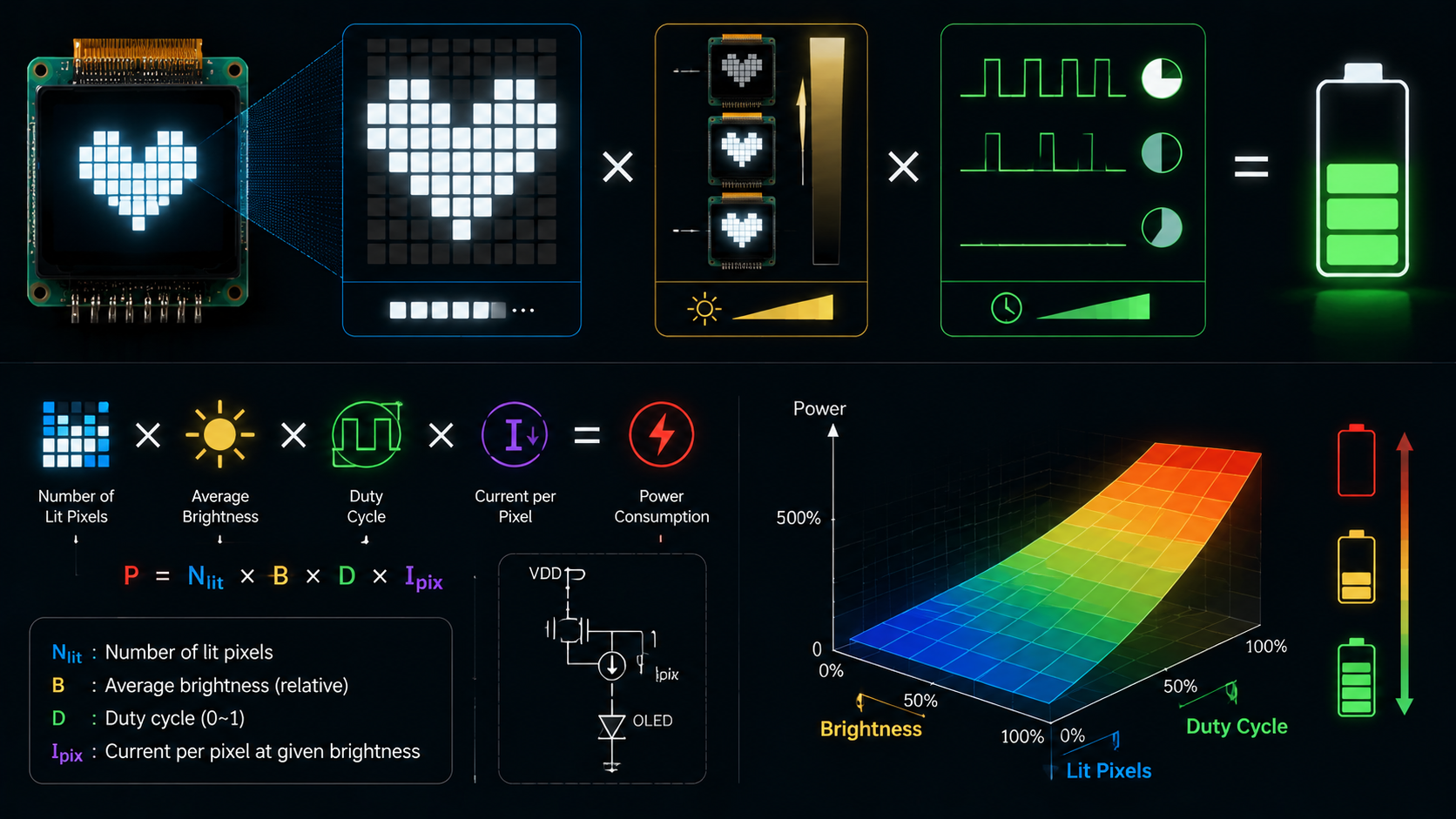
PMOLED power cannot be estimated from panel resolution alone. The result depends on the image pattern, grayscale level, segment current, multiplex ratio, display voltage, driver overhead, charge-pu...
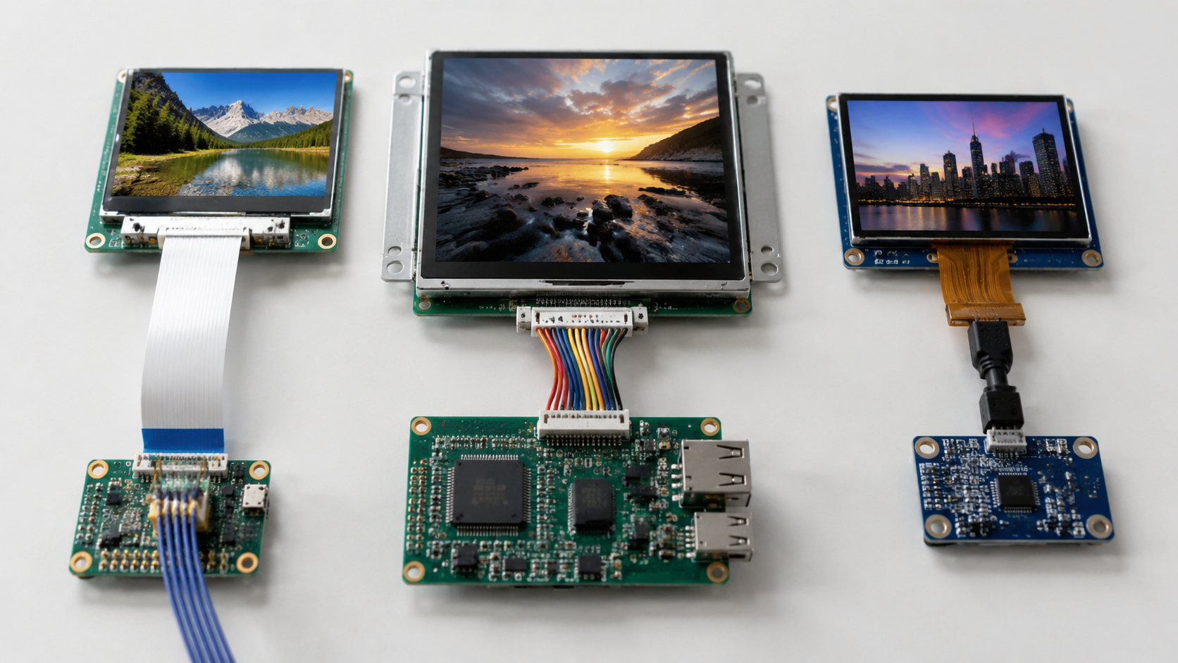
Choosing the right display interface is an unavoidable decision in hardware product development. The interface type directly affects display resolution, refresh rate, pin count, routing difficulty,...
Hinterlasse einen Kommentar
Diese Website ist durch hCaptcha geschützt und es gelten die allgemeinen Geschäftsbedingungen und Datenschutzbestimmungen von hCaptcha.