









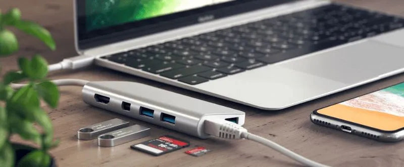
How To Use Standard Adapter With Displays
A standard adapter sits between a video source and a display module, converting one interface into another and often supplying the rails the panel needs. Using one well comes down to four checks: the interface and pinout, whether the adapter can carry your timing, how power and backlight are sequenced, and whether the resulting image is correct rather than merely present.
What a standard adapter does
Three jobs are usually bundled into one board. The first is interface conversion: HDMI, DisplayPort or VGA in, and parallel RGB, LVDS, MIPI DSI or SPI out. The second is timing, because the adapter generates the pixel clock, sync signals and blanking the panel expects. The third is power, meaning a regulated logic rail for the panel and a constant-current driver for the backlight.
Adapters differ in how much of that they include. A passive breakout carries no conversion at all, a bridge board converts one differential interface into another, and a scaler adds resolution and refresh conversion. Knowing which type is on the bench prevents most of the debugging that follows.
Most adapters are built around a specific panel family, so the standard adapter range is easier to navigate by output interface than by part number.
Match the interface and pinout
Two modules with a 40-pin FPC do not share a pinout. Pin order, lane count, colour mapping and the position of the supply pins differ between panel families — the TFT module range alone shows several distinct assignments — and an adapter built for one family will not drive the other even when the connector physically fits.
Compare four items before connecting anything: connector type and pitch, the pin assignment table, the rails the panel expects, and the backlight connection. If an adapter is documented with a wiring diagram rather than a pin list, ask for the pin list in writing. A wrong assignment can put a panel supply onto a signal line, and the damage is not always immediate.
The same discipline applies at the source end. A display that expects a hot-plug detect line will not be enabled if that line floats, which is a common reason a correctly wired panel stays dark.
Confirm the adapter carries your timing
Every interface is a bandwidth budget. For parallel RGB the budget is the pixel clock, which rises with resolution, refresh rate and blanking. For LVDS it is the number of channels plus the bit mapping. For MIPI DSI it is the lane count and the per-lane rate.
The practical test is arithmetic rather than guesswork. Multiply horizontal pixels by vertical lines by refresh rate, add the blanking intervals, and compare the result with the adapter's stated maximum pixel clock. If your figure exceeds that maximum, the adapter will either refuse the mode or output it with corrupted timing.
Colour depth counts too. An 18-bit RGB adapter driving a 24-bit panel, or an LVDS link in the wrong bit-mapping format, produces a picture that looks almost right: gradients band, or red and blue swap in patches. Both are mapping faults, not panel faults.
| Interface | What the adapter must provide | What to confirm first |
|---|---|---|
| Parallel RGB | Pixel clock, HSYNC, VSYNC, DE, 16/18/24-bit data | Pixel clock ceiling against your mode |
| LVDS | Single or dual channel, correct bit mapping | Channel count and mapping format |
| MIPI DSI | Lane count, DSI clock, video or command mode | Lane rate, and whether the panel expects commands |
| SPI | Clock, data, chip select, DC and reset lines | Whether the refresh rate you need is achievable at your clock |
Get power and backlight right
Panel logic and backlight are separate circuits and should stay separate. The logic rail is a regulated low-voltage supply, often with a defined power-up order relative to the panel's own supply. The backlight is a string of LEDs that needs a constant-current driver, typically a boost converter whose output depends on how many LEDs sit in series.
Wiring a backlight string to a fixed 5 V rail is a common shortcut and a common failure. Current is then set by the string's forward voltage rather than by the driver, so brightness varies between units and drifts as the panel warms. Use the adapter's backlight output, or a driver rated for the string voltage and current in the panel datasheet.
Power sequencing matters more than it appears. Where a datasheet states that logic must be stable before the panel supply, or that reset must be held for a defined interval, follow it. Adapters that bring every rail up at once can leave a panel latched in an undefined state, which then reads as a dead module.
One more rail is easy to forget: a capacitive touch controller needs its own supply and bus connection, and a silent panel is usually an unpowered controller rather than a broken sensor.
Set the source to the native mode
When the adapter presents an HDMI input, the source reads an EDID and picks a mode from that list. If the EDID advertises modes the panel cannot display, the host may choose one and the adapter will scale it or reject it. Editing the EDID, or choosing an adapter whose EDID matches the panel's native resolution, removes the problem at its origin.
Two further settings catch people out. HDCP on the source blocks the signal path unless every link in the chain supports it. And some operating systems fall back to a safe mode after a failed handshake, so the panel shows a correct-looking but non-native image.
Check the image, then the edges
A picture appearing is not the same as a correct picture. Three patterns do most of the diagnostic work. A one-pixel checkerboard exposes pixel mapping and any column or row offset. A grey ramp exposes bit-depth loss and gamma mismatch. A fine crosshatch exposes clock phase, where the adapter samples each pixel slightly early or late and the result is a shimmering vertical edge.
Most adapters expose a sampling-phase control for exactly this reason, and a single step usually clears the shimmer. If it survives the full range, suspect cable quality or cable length before replacing the panel.
Uniformity and flicker are worth measuring rather than judging by eye. ISO 9241-307 sets out analysis and compliance test methods for electronic visual displays and refers to the measurement procedures of ISO 9241-305, which is the correct basis for any luminance uniformity or flicker figure you intend to compare between units.[1]

Faults that look like a dead module
| Symptom | Usual cause | First check |
|---|---|---|
| Backlight on, no image | Timing mismatch or missing sync | Pixel clock and blanking against the panel datasheet |
| No backlight, image faintly visible | LED string not driven, or driver current at zero | Driver enable pin and set resistor |
| Image shifted sideways with a dark bar | Blanking values wrong for the panel | Front and back porch settings |
| Colours inverted or swapped | Bit mapping or colour order | Pin list, then the RGB or LVDS mapping table |
| Shimmering vertical edges | Sampling phase | Phase control, then cable |
| Touch silent | Controller supply or I2C address | Rail voltage, then a bus scan |
When a standard adapter is the wrong tool
An adapter is designed for bench work, evaluation and low-volume builds. Four situations call for a custom board instead. The first is mechanical, because a product enclosure rarely has room for a development board and its connectors. The second is environmental, since shock, vibration, condensation and wide temperature range sit outside what a consumer adapter is qualified for. The third is EMC, where an unshielded adapter and its cables act as both radiator and victim.
Volume is the fourth. Once the design is fixed, an integrated board is usually smaller, cheaper and more repeatable than an adapter plus hand wiring, and it removes a connector from the list of things that can fail in the field. The proven reference design usually transfers directly, so only the mechanical and power sections change.
A standard adapter is a fast way to prove a panel works and a poor way to ship a product. Match the pinout, do the bandwidth arithmetic, sequence the rails and measure the image. Those four checks separate a working prototype from a module wrongly judged faulty.
References
- ISO 9241-307:2008 — Ergonomics of human-system interaction — Part 307: Analysis and compliance test methods for electronic visual displays. International Organization for Standardization. https://www.iso.org/standard/40102.html
Weiterlesen
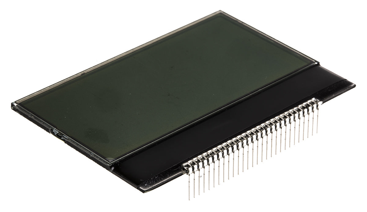
A COG (Chip on Glass) LCD Display Module integrates the driver IC directly onto the glass substrate, minimizing wiring and bulk; typically 1-3 inches in.

NexPCB supports XR displays by delivering tailored PCB solutions, including 12-layer HDI boards with ±25μm micro-via precision to fit compact headset.
Hinterlasse einen Kommentar
Diese Website ist durch hCaptcha geschützt und es gelten die allgemeinen Geschäftsbedingungen und Datenschutzbestimmungen von hCaptcha.