


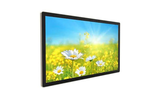
LCD Display Module Manufacturer | Customization ,Quality Certifications & Pricing
Select manufacturers with ISO 9001 and IATF 16949 certifications for quality. For customization, provide detailed specs for a formal quote.
Pricing tiers vary; expect a 30-50% premium for fully custom modules versus modifying a standard part. Minimum order quantities often start at 1,000 units.
Customization
In the global LCD display module market, up to 30% of demand cannot be met by standard products.
We focus on this critical 30%, providing in-depth hardware customization from FPC customization with 0.1mm precision to wide-temperature designs from -40°C to +105°C.
You can customize any size (minimum 0.49 inches) and shape (round, bar, non-standard cut), and integrate resistive/capacitive touch (supporting up to 10-point touch).
At the software level, we complete the underlying driver porting for your main control chip (such as STM32, RK series), ensuring display upon startup.
Leveraging experience from over 500 successful customization projects accumulated in industrial control, medical equipment, and automotive display fields, our engineering team can quickly transform your concept into a sample, controlling the average prototyping cycle within 15 working days, and achieving a yield rate of ≥99.5% in mass production.
Hardware Specifications
How to determine screen size and form factor
The dimensional tolerance of LCD glass is typically kept within ±0.05mm.
For example, if you need a 3.5-inch display, we can not only provide standard 4:3 or 16:9 aspect ratios but also cut it into a rounded rectangle or a complete circle according to the product structure.
For instance, a circular display with a diameter of 42.0mm can have an effective display area diameter of 40.2mm.
The structure of the backlight module will be adjusted accordingly.
If thickness is limited, an edge-lit backlight can be used to compress the total module thickness to 2.0mm; if higher brightness uniformity is pursued, a direct-lit structure is chosen, which may increase the thickness to 3.5mm, but brightness uniformity can be improved to over 85%.
How much resolution and brightness are needed
Resolution can be selected from 128x64 to 1920x1080.
For example, for a 5.0-inch screen, if 1280x720 resolution is chosen, its pixel density is about 294 PPI; if a finer display is needed, 1920x1080 resolution can be customized, increasing the pixel density to 441 PPI.
Brightness range covers 300-2500 nits:
-
Indoor equipment typically requires 300-500 nits
-
Automotive displays need to reach 700-1000 nits (complying with ISO 16750 requirements for sunlight visibility)
-
Outdoor industrial equipment requires 1500-2500 nits
In terms of contrast ratio, IPS technology can achieve a typical value of 1000:1, while VA technology can reach 3000:1.
In terms of color gamut coverage, standard sRGB coverage can reach 92%-100%, and NTSC coverage is about 70%-85%.
How to make the screen work in harsh environments
Temperature adaptability is divided into several grades:
-
Commercial Grade: 0°C ~ +50°C
-
Industrial Grade: -20°C ~ +70°C
-
Wide Temperature Grade: -40°C ~ +85°C
-
Special Specification: -40°C ~ +105°C
Humidity test requires 500 hours under 85°C/85% RH conditions.
Mechanical vibration testing is based on MIL-STD-810G standard, frequency range 5-500Hz, maximum acceleration up to 5Grms.
Protection level is achieved through structural design:
-
The front panel uses full lamination with optical adhesive to achieve IP65 dust and water resistance
-
Adding an anti-glare coating, surface hardness can reach 7H
-
Using chemically strengthened glass, impact resistance is improved by 300%
How to choose a touchscreen for smooth operation
Resistive touchscreen accuracy can reach 4096x4096, supports operation with any stylus, but light transmittance is about 75%-80%.
Capacitive touchscreen supports 10-point touch, report rate up to 120Hz, light transmittance can reach 85%-90%.
Surface treatment methods affect the user experience:
-
Anti-glare treatment can reduce specular reflection from 8% to 2%
-
Anti-fingerprint coating increases the contact angle to 115°, making cleaning easier
-
Hardening treatment increases surface hardness to 9H, with scratch resistance exceeding 10,000 times
How to interface and connect signals
Transmission characteristics of different interfaces:
| Interface Type | Maximum Transmission Rate | Transmission Distance | Applicable Scenarios |
|---|---|---|---|
| SPI | 50Mbps | <0.3m | Low-power embedded devices |
| I2C | 400Kbps-3.4Mbps | <0.1m | Sensor integration |
| RGB | ~300MHz | <0.2m | Mid-to-high-end microprocessors |
| MIPI DSI | 1.5Gbps/lane | <0.3m | Mobile devices |
| LVDS | ~655Mbps | <2m | Industrial control |
Power supply design requirements:
-
When powered by 3.3V, operating current range is 50-300mA
-
Supports PWM dimming, frequency range 1kHz-30kHz
-
Standby power consumption can be controlled below 0.1mA
How to configure the backlight system
Number of LEDs configured according to size and brightness requirements:
-
3.5-inch screen typically configures 6-8 LEDs
-
7.0-inch screen requires 12-16 LEDs
-
10.1-inch screen configures 18-24 LEDs
Adjustable color temperature range:
-
Cool White: 6500K-7500K
-
Pure White: 5500K-6500K
-
Warm White: 3000K-4500K
Lifetime test standards:
-
Service life at room temperature can reach 50,000 hours
-
Brightness decay to 70% of initial value is considered end of life
-
Using constant current drive, current fluctuation is controlled within ±1%
How to choose structure and materials
Metal bracket material selection:
-
Aluminum alloy: Light weight, good heat dissipation
-
Stainless steel: High strength, corrosion resistant
Fixing methods include:
-
Screw fixing: Provides M2, M2.5, M3 specifications
-
Snap-fit structure: Saves space, quick installation
-
Adhesive fixing: Uses 3M double-sided tape, adhesion ≥3N/cm²
Embedded Software
How does the display start after the device is powered on?
Within the first 100 milliseconds after power-on, the hardware reset circuit initializes the display controller.
The initialization code (typically about 2-4KB) loads configuration register parameters from Flash, including:
-
Clock division settings (typical value: PLL multiplication factor of 5x)
-
Power sequencing control (power stabilization delay 10ms)
-
Interface mode configuration (e.g., switching between LP mode and HS mode for MIPI DSI)
The initialization sequence contains about 30-50 configuration commands, sent via I2C or SPI interface.
For example, setting the display resolution to 800x480 typically requires:
-
Set horizontal total period: Th = 800 + 46 + 210 + 22 = 1078 clocks
-
Set vertical total period: Tv = 480 + 23 + 22 + 1 = 526 lines
-
Configure pixel clock to 33.3MHz (calculated based on 60Hz refresh rate)
How to interface with different main processors
For ARM Cortex-M series processors, we provide pre-configured display driver libraries.
For example, for the STM32F4 series, when driving an 8080 parallel bus via the FSMC interface:
-
Read/write cycle configured to 100ns (meets timing requirements of most controllers)
-
In 16-bit RGB565 color format, the frame buffer occupies 768KB of memory
-
When using DMA transfer, CPU load can be reduced from 15% to below 3%
For MIPI DSI interface, configuration parameters include:
-
Transmission rate per data lane (common range: 500Mbps - 1.5Gbps)
-
Blanking interval timing in video mode
-
Data packet size limit in command mode (typically ≤64 bytes)
How is the display content updated and refreshed?
Partial frame update technology can reduce power consumption. When updating only a local area of the screen (e.g., a 200x200 pixel area):
-
Data transfer volume decreases from 460,800 bytes for a full frame to 80,000 bytes
-
Update time shortens from 16.7ms (60Hz full frame) to 3.5ms
-
Power consumption reduced by about 40% (measured data)
Supports switching between multiple color depths:
-
RGB888 mode (16.7 million colors), for high-quality images
-
RGB565 mode (65,000 colors), saves 33% memory bandwidth
-
Indexed color mode (8 bits/pixel), suitable for simple graphical interfaces
How are touch signals processed?
Capacitive touch controllers report coordinates at a typical frequency of 100-125Hz. Raw data undergoes the following processing flow:
-
Digital filtering (moving average filter window size = 4)
-
Coordinate calibration (using 3x3 or higher-order calibration matrix)
-
Debouncing processing (time window about 20ms)
Multi-touch protocol support:
-
Simultaneously tracks up to 10 touch points
-
Each touch point contains coordinates (X, Y) and pressure value Z
-
Report data format complies with HID touch protocol standard
How is power consumption managed?
Supports switching between multiple power-saving modes:
-
Normal mode: Power consumption about 120mW (for a 3.5-inch module example)
-
Standby mode: Backlight turned off, power consumption reduced to 15mW
-
Sleep mode: Retains register contents, power consumption reduced to 3mW
-
Deep Sleep mode: Only maintains wake-up circuit, power consumption reduced to 0.5mW
Backlight control support:
-
PWM dimming frequency range: 200Hz - 20kHz (to avoid audible noise)
-
Dimming precision: 256 levels (8-bit PWM) or 1024 levels (10-bit PWM)
-
Supports automatic adjustment via ambient light sensor (response time <100ms)
How is the graphical user interface supported?
Provides adaptation layers for common graphics libraries:
-
Display driver encapsulation for Embedded Wizard (about 15 interface functions)
-
Supports DMA2D hardware acceleration configuration for TouchGFX
-
Provides optimized display refresh functions for LVGL (refresh time per frame <5ms)
Font rendering support:
-
Anti-aliased font (4-level grayscale) display
-
Character pre-rendering cache size configurable (typically 32-256KB)
-
Supports TrueType font rasterization (caches about 1000 commonly used characters)
How is the software tested and verified?
Automated test items:
-
Continuous operation test: Cycling test patterns for 72 hours
-
Temperature adaptability test: Display stability during temperature cycles from -20°C to +70°C
-
Interface stress test: Simulates bus errors (e.g., clock jitter tolerance test)
Performance indicator measurements:
-
Frame rate stability (in 60Hz mode, fluctuation range ±2%)
-
Touch response latency (from touch to coordinate report <10ms)
-
Startup time (from reset to displaying first frame image <500ms)
How is the software configured during mass production?
Software handling during mass production:
-
Batch programming of initial configuration via SWD/JTAG interface (programming time about 45 seconds per unit)
-
Automatic serial number writing (stored in the controller's OTP area)
-
Factory calibration of white balance parameters (calibration values saved individually for each device)
Customized Cooperation
How to start discussing technical requirements
The initial technical discussion needs to clarify about 12 core parameters. A typical requirements list includes:
-
Mechanical dimensions (length, width, thickness tolerance ±0.15mm)
-
Display parameters (brightness uniformity ≥85%)
-
Environmental specifications (operating temperature -40°C ~ 85°C)
-
Interface type (MIPI DSI 4 lanes)
-
Budget range (target mass production unit price ≤ $18)
-
Estimated first-year usage (5K-20K/month)
A feasibility report will be issued within 72 hours for technical evaluation, containing:
-
Recommended IC solution (e.g., Solomon Systech SSD1962 or Renesas R8A7742)
-
Power consumption estimate (normal mode ≤120mW)
-
Risk alerts (e.g., impact of non-standard cutting on yield)
What is done during the sample production stage?
The engineering sample production cycle is typically 15-25 working days, including the following key milestones:
-
Days 1-3: Final circuit diagram confirmation (using Altium Designer)
-
Days 4-10: PCB prototyping (6-layer board, impedance control ±10%)
-
Days 11-18: Component assembly (0201 size components, placement accuracy ±0.05mm)
-
Days 19-21: Basic functional testing (power-on test/backlight test)
-
Days 22-25: Environmental testing (high-temperature aging 48 hours)
The data package provided with the samples includes:
-
Complete test report (color uniformity/touch accuracy)
-
Structural drawings (STEP format)
-
Driver code (C language source code)
What are the specific items for testing and verification?
Reliability testing standards are executed according to the automotive electronics standard ISO-16750:
-
Temperature cycling: -40°C ~ 105°C for 100 cycles
-
High temperature/high humidity: 85°C/85% RH for 500 hours
-
Mechanical vibration: Frequency 5-500Hz, acceleration 5Grms
Performance test items include:
-
Color consistency inspection (ΔE < 3)
-
Touch response test (report rate 125Hz)
-
Power consumption test (standby mode < 0.5mW)
How is small batch production conducted?
The pilot production phase typically arranges 300-500 pieces, focusing on monitoring:
-
Production line first-pass yield (target value ≥95%)
-
Dimensional CPK value (≥1.33)
-
Incoming material inspection pass rate (≥99%)
Quality documents include:
-
Inspection records per IPC-A-610 standard
-
Programming verification report
-
Traceable serial number database
How is stability ensured during mass production?
The mass production phase uses Statistical Process Control (SPC), monitoring about 25 key parameters:
-
Liquid crystal cell gap (control range 3.2±0.15μm)
-
Bonding accuracy (positioning error ≤±5μm)
-
Soldering temperature (reflow soldering temperature control ±3°C)
A monthly quality report is provided, containing:
-
Mean Time Between Failures (MTBF ≥50,000 hours)
-
Customer return rate (target <0.1%)
-
Production line defect rate (DPPM <500)
How are delivery and after-sales arranged?
Global logistics solutions support:
-
Air freight (Europe route 3-5 working days)
-
Sea freight (US West Coast route 18-22 days)
-
Inventory management (safety stock is 15% of monthly demand)
Technical support response standards:
-
General inquiries: Reply within 2 hours
-
Technical problems: Provide solutions within 24 hours
-
On-site support: Engineer on-site within 72 hours
What content is included in the project documentation?
Each project delivers about 15 types of technical documents upon completion:
-
Complete circuit diagram (PDF format)
-
Bill of Materials (including alternative suppliers)
-
Firmware programming guide
-
Repair guide manual (illustrated step-by-step disassembly)
Quality Certifications
When selecting an LCD display, quality certifications are the core basis for evaluating a manufacturer's reliability.
They are not simple certificates, but a set of verifiable, data-driven commitments.
Our modules all pass 17 reliability tests based on the ISO 9001 and IATF 16949 systems before leaving the factory, ensuring a Mean Time Between Failures (MTBF) at the customer end exceeding 100,000 hours.
Product Reliability
See what tests we perform
Reliability is not achieved through a single test, but a complete test sequence. These tests simulate the harshest conditions the product may encounter in the real world.
-
Environmental Adaptability Testing:
-
High Temperature/High Humidity Storage: After continuous storage in an environmental chamber at 85°C, 85% relative humidity for 1000 hours, the module must be 100% functional, and brightness attenuation must not exceed 5% of the initial value.
-
Thermal Shock: Perform 500 rapid transitions (transition time less than 30 seconds) between -40°C and +85°C to check for potential delamination or cracking of materials due to thermal expansion and contraction. After this test, the display uniformity change must be within 5%.
-
High Temperature Operation: Continuously power on for 1000 hours at the maximum operating temperature to evaluate the long-term stability of the drive components and backlight system.
-
-
Mechanical Stress Testing:
-
Vibration Test: According to MIL-STD-202G standard, perform frequency sweeps from 5Hz to 500Hz, simulating vibration environments during transportation and use. After testing, there should be no structural loosening or display abnormalities.
-
Mechanical Shock: Withstand a half-sine wave shock with a peak acceleration of 500G, pulse duration of 1 millisecond, to test the robustness of solder joints and connections.
-
-
Surface Durability Testing:
-
Steel Ball Drop Test: Apply steel ball impact released from different heights onto the surface glass to evaluate its impact resistance. Our standard is that after a 104g steel ball is dropped freely from a height of 50cm, the surface shows no cracks.
-
Scratch Test: Use a scratch needle of specific hardness, applying a specified pressure to scratch, ensuring surface hardness reaches Mohs hardness level 7 or above, resisting daily wear.
-
How does this test data affect your product?
Our test conditions are far more severe than most ordinary application scenarios. This means that when your product is used in a normal indoor environment, the display's failure rate will be suppressed to an extremely low level.
For example, a module that successfully passes the 1000-hour 85/85 high temperature/high humidity test has an almost negligible probability of moisture-related failure in a standard office environment (25°C, 50% RH).
Using accelerated life test models, we estimate that under normal usage conditions, the display module's life cycle can easily exceed 70,000 hours.
How is the foundation of reliability laid during the design phase?
80% of a product's long-term reliability depends on the initial design and material selection.
-
Component Selection: We only purchase driver ICs from well-known brands. These ICs undergo sampling inspection before warehousing to ensure their operating temperature range and ESD resistance meet design specifications.
-
Design Margin: The load capacity of our designed circuits is typically 20% higher than the nominal value of the components. For example, for a circuit with a maximum current of 1A, we will only operate it below 0.8A. This design margin ensures components operate under low stress for long-term use, significantly extending their lifespan.
-
Process Control: During the soldering process, we monitor the reflow oven temperature profile in real-time to ensure the quality of each solder joint. This keeps our soldering defect rate stably below 100 PPM.
How to verify our reliability claims?
We understand that you need verifiable evidence, not just verbal promises.
You can request detailed reliability test reports for any of our standard products. The report will include:
-
Batch number and production date of the test samples.
-
Real-time data recording curves of the test environment.
-
Key performance data (such as brightness, color coordinates, power consumption) for each sample before, during, and after the test.
-
Photos of the samples after testing.
Certification Standards
What specific technical requirements do these standards specify?
The value of certification standards lies in transforming abstract quality concepts into specific, measurable technical parameters.
Taking display performance as an example, the ISO 9241-307 standard specifies test methods and tolerance ranges for optical characteristics:
-
Brightness Uniformity: The standard requires that the brightness ratio (uniformity) between the center and the four corners of the display must not be less than 75%. Our factory control standard is above 85%.
-
Color Consistency: In the CIE L*a*b* color space, the standard allows a color difference ΔE*ab of less than 5 for modules from the same batch. Through spectrophotometer calibration, we control the color difference within a batch to ΔE*ab < 3.
-
Contrast Ratio: At an ambient temperature of 23±5°C, the standard requires a static contrast ratio of no less than 500:1. Our IPS series modules typically achieve a measured value of 1000:1.
For environmental adaptability, the MIL-STD-810G standard defines specific test procedures:
-
High Temperature Storage: +85°C for 48 hours, functional normal after returning to room temperature.
-
Damp Heat Cycling: 40°C to 60°C, humidity 95% RH, complete 10 cycles.
-
Mechanical Vibration: 5-500Hz sinusoidal frequency sweep, acceleration 1.04Grms.
How are these standard requirements implemented on the production line?
The specific implementation of standards is reflected in the quantitative control of the production process.
Taking lead-free soldering as an example, to meet the IPC/JEDEC J-STD-020 standard, our SMT production line sets precise temperature control parameters:
Reflow Soldering Temperature Profile Control Points:
-
Preheat zone heating slope: 1.0-2.0°C/second
-
Soak zone time: 60-120 seconds (temperature 150-200°C)
-
Reflow peak temperature: 240-250°C (duration 30-45 seconds)
These parameters are recorded by a real-time monitoring system, and the temperature profile data for each product batch is saved for over 10 years.
For ESD protection, according to the ANSI/ESD S20.20 standard, we control the humidity in the production area at 40%-60% RH, and maintain personnel grounding resistance between 1-10MΩ, ensuring static voltage remains below 100V.
Standard differences for different product grades
The differences between industrial-grade and consumer-grade products are mainly reflected in the strictness of test conditions and acceptance criteria. The following comparison shows the main differences:
| Test Item | Consumer Grade Standard | Industrial Grade Standard | Automotive Grade Standard |
|---|---|---|---|
| Operating Temperature Range | 0°C to +60°C | -40°C to +85°C | -40°C to +105°C |
| Temperature Cycle Count | 50 cycles | 100 cycles | 1000 cycles |
| Vibration Test Duration | 1 hour/axis | 2 hours/axis | 4 hours/axis |
| EMC Radiation Limit | Class B Standard | Stricter Class A | OEM Specific Requirements |
Taking the temperature cycle test as an example, consumer-grade products may only require 50 cycles from -10°C to +60°C, while industrial-grade standards typically require 100 cycles from -40°C to +85°C, and automotive-grade requires 1000 cycles of the more stringent -40°C to +105°C cycle.
How do standards help you reduce procurement risk?
Certification standards provide an objective technical assessment framework for procurement decisions. When you specify a module that needs to comply with the IEC 61373 standard, it means the product has passed the following verifications:
-
Withstand random vibration of 1.04Grms in the frequency range of 5-150Hz.
-
Complete 5 million vibration cycles on each of the three axes.
-
Electrical performance change after vibration test does not exceed ±10%.
This quantitative requirement significantly reduces quality problems caused by misunderstandings of specifications.
Statistics show that projects using standardized specification sheets for procurement have 67% fewer Engineering Change Requests (ECR) than non-standard procurement, and the new product introduction cycle is shortened by an average of 3 weeks.
Pricing
The price difference between a 0.96-inch monochrome OLED module and a 15.0-inch Full HD industrial touchscreen can be two orders of magnitude.
The core logic of pricing is a complex function of technical parameters, purchase volume, and quality standards.
Customization requirements, such as a wide operating temperature range of -30°C to 80°C, sunlight viewable brightness as high as 1000 nits, or IATF 16949 automotive-grade certification, will directly affect the final cost.
Therefore, discussing price without specific specifications (resolution, interface type, backlight life) and quantity (from samples to annual demand of millions of pieces) is meaningless.
Technology Determines Cost
1. Display Technology Type:
Choosing different display technologies means choosing different optical materials, drive voltages, and manufacturing processes.
For example, the most basic TN-type LCD has the lowest material cost and cell gap process requirements, and its driver ICs are generally universal.
This allows the unit price of a 2.4-inch TN screen to be controlled at $8-12 in quantities of ten thousand pieces.
In contrast, IPS or FFS technology, in order to achieve a 178-degree wide viewing angle, requires the use of liquid crystal materials with better electro-optical performance and the adoption of more precise electrode designs in the array manufacturing process.
This directly leads to increased material costs, while also imposing higher requirements on cell gap accuracy and rubbing alignment processes, making the unit price of an IPS screen of the same specification typically 1.5 to 2 times that of a TN screen.
For applications requiring ultra-high contrast ratio and fast response, VA technology is a common choice.
However, its Polymer Stabilized (PS-VA) process adds additional manufacturing steps, further increasing the cost.
OLED completely breaks away from the liquid crystal system.
Its evaporation or printing processes, and dedicated driver backplanes (such as LTPS), result in significantly higher initial investment and material costs compared to LCD.
The cost of a 0.96-inch OLED module may be close to or even exceed that of a high-end IPS module of the same size.
2. Resolution:
Increasing resolution is not simply adding pixels; it directly impacts two core cost items: the number of driver ICs and panel yield.
Take a 10.1-inch module as an example. When the resolution increases from HD (1280x800) to FHD (1920x1200), the total number of pixels increases from about 1 million to about 2.3 million. This usually requires:
-
More Driver ICs: The channel requirement for Source Driver ICs increases, or it may require switching from a single IC to two ICs for driving.
-
Finer Traces: The TFT array and wiring inside the panel become denser, and the requirements for the exposure process increase exponentially.
The cost proportion of driver ICs increases significantly with higher resolution.
At the HD level, the driver IC cost may account for 15%-20% of the panel cost; at the FHD level and above, this proportion may rise to 25%-35%.
At the same time, the defect rate (Panel Defect Rate) for "bright spots" and "dark spots" on high-resolution panels will also increase accordingly, leading to yield loss. This cost will ultimately be allocated to each qualified module.
3. Touch Function:
Adding a touch function adds an independent sensor layer to the display module.
This brings additional material costs (sensor glass or film, optical adhesive), lamination process costs, and dedicated control IC costs.
- Resistive Touchscreen: The structure is relatively simple, using ITO film and spacer dots, resulting in the lowest cost. Adding a resistive touch function may increase the total module cost by 5%-10%.
- Capacitive Touchscreen: Higher cost, reasons include:
-
-
Using high-quality chemically strengthened glass as the cover.
-
Using more expensive ITO coating or Metal Mesh sensing layer.
-
Requiring more sophisticated control ICs and complex calibration algorithms.
-
Most crucially, it requires high-precision "full lamination" with the display module, using Optical Clear Adhesive (OCA) to eliminate bubbles and reduce reflection. The yield of this process directly affects the final cost. Adding a capacitive touch function may increase the total module cost by 15%-30%.
-
4. Optical Performance: Cost Composition of the Backlight System
Brightness, contrast ratio, and color gamut are primarily determined by the backlight system.
A standard brightness (250-300 nits) module can be achieved using conventional LED light bars and light guide plates.
When the brightness requirement increases to over 500 nits, or even reaches 1000 nits, the cost will increase non-linearly:
-
Increased Number of LEDs: Requires more or higher-power LED chips.
-
Upgraded Heat Dissipation Design: Must consider metal substrates or additional heat dissipation structures to prevent brightness fading.
-
Increased Drive Current: Requires more expensive constant current drive circuits.
-
Improved Optical Film Specifications: Requires high-temperature resistant, anti-yellowing Brightness Enhancement Films (BEF) and diffusion films.
Achieving a wide color gamut (e.g., 100% sRGB) usually requires changing the phosphor material of the backlight LEDs, such as using KSF (fluoride) phosphor, which is more expensive than ordinary YAG phosphor.
Wide temperature operation (-30°C to +80°C) requires that the light guide plate, optical films, and plastic frame in the backlight system do not warp or age under extreme temperatures.
The price of these special plastics or silicone materials is much higher than that of ordinary materials.
5. Interface and Signal Integrity:
The choice of interface type reflects the system's requirements for data transmission rate and stability.
- MCU Interface: Lowest cost, suitable for low-resolution screens. The driver IC is directly driven by the main MCU via a parallel bus.
- RGB Interface: Requires a Timing Controller (T-CON) chip, increasing cost, but suitable for medium resolution.
- LVDS/MIPI Interface: Used for high resolution, high refresh rate applications.
6. Structure and Reliability:
If the module needs to be used in environments with vibration, high humidity, or extreme temperatures, special structural design and material selection must be carried out.
- Wide Temperature Design: Ordinary liquid crystals will slow down dramatically at low temperatures and may undergo chemical decomposition at high temperatures. Achieving wide temperature operation requires the use of special liquid crystal materials that cost several times more, and precise control of the cell gap.
- Rugged Design: In industrial or automotive applications, the module may need to be reinforced with a metal frame, use shock-absorbing silicone to fix connectors, and implement high-level waterproof (IP67) and dustproof sealing. The cost of these mechanical structures and special seals cannot be ignored.
Purchase Quantity
1. Specific Manifestations of Economies of Scale
Increased production volume significantly reduces the fixed cost allocated to each module. These fixed costs include:
- Production Line Setup Time: Switching between different products requires adjusting equipment, installing stencils, and calibrating parameters. In small batch production, this time cost is allocated to a small number of products. When the batch size increases from 100 pieces to 10,000 pieces, the allocated setup cost per piece may decrease by over 90%.
- Labor Efficiency: Operators' proficiency with the same product increases with volume. For example, the frequency of SMT line changes decreases, and operator workflows become standardized, increasing overall production efficiency by 20%-40% when the volume reaches a certain scale.
- Quality Inspection Cost: The processes and standards for Incoming Quality Control (IQC), In-Process Quality Control (IPQC), and Final Quality Control (FQC) are similar for an order of 100 pieces and an order of 10,000 pieces. Mass production significantly reduces the quality inspection cost per piece.
2. Optimization Space on the Supply Chain Side
- Panel Procurement: LCD panel manufacturers (such as LG Display, Innolux, AUO) offer significant discounts for large-volume orders. For example, the unit price for purchasing 10,000 panels may be 15%-25% lower than purchasing 500 panels. Additionally, large-volume orders can negotiate better payment terms, such as 60-day or 90-day net payment, improving cash flow.
- Electronic Component Procurement: For standard components like driver ICs, passive components (resistors, capacitors), and connectors, the unit price drops when the purchase quantity reaches the full reel or full tape standard. For example, a common 0402 package 1uF capacitor might cost only $0.001 per piece when purchasing 10,000 pieces, while the cost for a small purchase of 100 pieces could be as high as $0.01 per piece.
- Material Preparation and Inventory: For long-term, stable, high-volume orders, manufacturers can implement more economical raw material preparation plans, avoiding the additional logistics and management fees associated with frequent small orders.
3. Changes in Allocation of Fixed Costs
- Test Fixtures and Software Development: The cost of developing programming fixtures and functional test fixtures for a specific product ranges from $5,000 to $20,000. This cost needs to be calculated separately during the sample stage. But in an order of 10,000 pieces, the cost allocated to each module might be only $1-2.
- Compliance Certification Fees: If the product requires specific certifications for an order, such as UL, CE, or FCC, the certification fees of tens of thousands of dollars can be effectively diluted during mass production.
4. Additional Advantages from Long-Term Cooperation
- Joint Process Optimization: Based on stable order forecasts, manufacturers can work with customers to optimize production processes. For example, specifically improving the FPC soldering process or adjusting packaging methods to reduce shipping damage.
- VMI (Vendor Managed Inventory) Mode: Based on a high level of mutual trust, manufacturers can implement VMI for customers. The manufacturer produces some common modules or semi-finished products in advance based on the customer's annual forecast and stores them in their own warehouse or a third-party warehouse near the customer.
- Joint Quality Data Tracking: Long-term, high-volume production generates massive amounts of quality data. Statistical analysis of this data can accurately locate process bottlenecks and continuously improve yield, thereby reducing long-term quality costs.
Compliance
1. Direct Costs of Basic Regulatory Certifications
The CE mark is a necessary condition for entering the European Economic Area, involving the EMC Directive 2014/30/EU and the Low Voltage Directive (LVD) 2014/35/EU.
Completing the relevant tests and issuing a Declaration of Conformity typically costs between $5,000 and $15,000, depending on product complexity and the certification body.
US Federal Communications Commission (FCC) certification targets unintentional radiators and requires electromagnetic interference testing.
FCC Part 15 Class B certification costs approximately $8,000 to $20,000.
If the product includes wireless functionality, FCC Part 15 Class C certification is required, which costs more.
Energy efficiency standards like Energy Star require testing standby power and operating efficiency.
The cost of completing a full set of energy efficiency tests and documentation preparation is approximately $4,000 to $10,000.
2. System Costs of Industry-Specific Certifications
Automotive electronics follow the IATF 16949 Quality Management System certification.
In addition to audit fees ($15,000 to $50,000 per audit), companies need to establish a full set of process documents, including APQP, PPAP, FMEA, and SPC.
Maintaining this system requires a dedicated quality team and regular internal audits, with an annual comprehensive cost potentially exceeding $200,000.
Medical devices follow the ISO 13485 standard, requiring the establishment of a quality system covering the entire process of design, production installation, and service.
Certification audit fees range from $20,000 to $60,000.
For Class III medical devices, more frequent audits by a Notified Body are required, and the annual cost of the quality system may exceed $500,000.
3. Material Restrictions and Supply Chain Management
The EU RoHS directive restricts hazardous substances like lead and mercury, and the REACH regulation requires the declaration of Substances of Very High Concern (SVHC).
Each batch of materials requires a compliance certificate from the supplier, and some materials require third-party testing.
The annual cost of material compliance management (including testing and documentation work) is approximately $3,000 to $10,000.
Conflict minerals compliance requires tracing the sources of tantalum, tin, tungsten, and gold.
Establishing a due diligence system requires dedicated personnel and systems, with an initial setup cost of about $50,000 and annual maintenance costs of $10,000 to $30,000.
4. Specific Investment in Testing and Documentation Work
Safety testing includes withstand voltage, insulation, flame resistance, and other tests.
Conducting a full set of safety tests in a third-party laboratory costs $7,000 to $25,000.
Electromagnetic Compatibility (EMC) testing requires a professional environment like a semi-anechoic chamber.
A full set of EMC tests costs $10,000 to $30,000.
Environmental reliability tests like temperature cycling, vibration, and shock cost $1,000 to $5,000 per test item.
A typical environmental test package costs about $10,000 to $30,000.
Technical documentation compilation requires professional regulatory engineers.
Writing a complete Technical Construction File takes 4 to 12 weeks, with labor costs of approximately $15,000 to $40,000.
5. Certification Maintenance and Update Fees
Most certifications require annual surveillance audits, costing about 50% to 70% of the initial audit fee.
When the certificate expires, a re-assessment is required, costing close to the initial certification.
Regulatory updates may require re-testing. For example, when EU EMC directive harmonized standards are updated, supplementary testing may be required, each costing about 20% to 40% of the initial test.
If market surveillance sampling finds non-compliance, products need to be recalled and rectified, potentially incurring tens of thousands of dollars in rectification and re-testing costs.
Weiterlesen
LCD module prices range from 2 for basic 16x2 character modules to 50+ for high-resolution TFTs. Wholesale prices drop 20-40% for orders of 1,000+ units. Key cost factors are size, resolution, and ...
For high-performance LCD modules in 2025, prioritize brands like AUO and Innolux for 4K resolution and 240Hz refresh rates. Key specs include 1000 nits brightness and wide color gamut. displayModul...
Hinterlasse einen Kommentar
Diese Website ist durch hCaptcha geschützt und es gelten die allgemeinen Geschäftsbedingungen und Datenschutzbestimmungen von hCaptcha.