

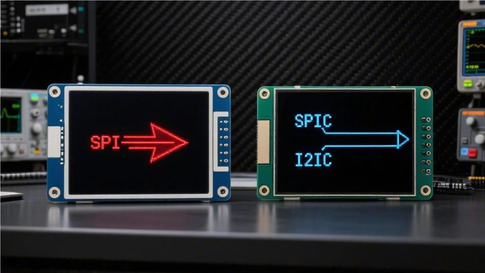
SPI vs I2C Display Interfaces | Speed & Use Cases
Use SPI when the display shows colour, animation or anything that must refresh quickly. Use I2C when the display is small, monochrome, and updated occasionally. The dividing line is not preference but arithmetic: SPI moves tens of megabits per second over four wires, while I2C tops out at a few hundred kilobits over two.
Pin count and wiring
SPI needs a clock, a data line from host to display, a chip select and usually a data or command selector — four signals, sometimes three when the display accepts a nine-bit protocol. I2C needs two: a clock and a bidirectional data line, with pull-up resistors on both.
On a large board the difference is trivial. On a flex tail feeding a 0.96-inch panel inside a handheld enclosure, two traces instead of four can decide whether the design routes at all.
The bandwidth arithmetic
Frame time follows from the payload size and the usable bit rate. For I2C, each byte costs nine clock periods once the acknowledge bit is counted, so a 400 kHz bus carries roughly 44 kB per second in theory and less after addressing and register overhead. For SPI, the clock is the byte rate divided by eight, minus a small command overhead.
The table applies that arithmetic to three common payloads. Your own numbers will differ with the controller, the driver and the amount of per-frame setup, but the ratios hold.
| Payload | I2C at 400 kHz | SPI at 10 MHz | SPI at 20 MHz |
|---|---|---|---|
| 128 × 64 mono, 1 kB | ~25–30 ms per frame | ~1 ms | ~0.5 ms |
| 240 × 240 RGB565, ~115 kB | ~2.6 s per frame | ~92 ms | ~46 ms |
| 320 × 240 RGB565, ~154 kB | Not practical | ~123 ms | ~61 ms |
Two conclusions follow. A monochrome status display on I2C is comfortable: a frame every 30 ms is faster than most text updates need. A colour display on I2C is not a bandwidth problem to be optimised but a category error, because a single frame takes seconds.
Read these figures with three conditions attached: the SPI clock actually achieved, the colour depth of the frame, and the frame rate the application needs. A supplier who quotes "SPI is fast" without those three numbers is not giving a specification.
Why I2C edges are slow
I2C uses open-drain outputs. The host pulls the line low actively, but releases it to rise: a pull-up resistor charges the bus capacitance through an RC curve. With a few kilohms of pull-up and a hundred picofarads of bus capacitance, the rise time eats a large share of the high phase of the clock.
That is why long cables force I2C down to a lower speed. Adding a metre of ribbon cable adds capacitance, the rising edge stretches, and the bus must slow to keep setup and hold times valid. The standard allows fast mode at 400 kHz, fast-mode plus at 1 MHz and high-speed mode at 3.4 MHz, but each step needs a stronger pull-up, a shorter bus, or an active buffer.
Why SPI tolerates capacitance
SPI drives both directions with push-pull outputs, so the line is actively pulled high as well as low. The output impedance is low, the RC time constant collapses, and edges stay square over much more capacitance and length.
The trade is pin count and no acknowledgement. SPI has no built-in way for the display to say it received the data, so a corrupted frame shows up as visual noise rather than as a retry.
Display RAM changes the answer
Many small controllers hold a frame buffer and refresh the panel themselves. With that RAM, the host only sends the pixels that changed, and I2C becomes viable for a surprisingly large panel — a clock, a menu, a sensor readout.
Separating the refresh loop from the host link is an old idea in flat-panel design, and it is the reason a slow bus can still serve a large panel.[1] Panels without a frame buffer must be streamed continuously. Every refresh costs a full frame, so the bus must support the frame rate, not the update rate. Check whether the controller has GRAM before comparing speeds; this single fact reshapes the decision more than the clock rate does.
Sharing the bus
I2C is a bus by design: many devices share two wires, each with a seven-bit address, and the host arbitrates. That is a real advantage when a product carries a display, a sensor, an EEPROM and a touch controller. Address collisions are the usual failure, and some parts offer only two or three selectable addresses.
SPI shares clock and data but needs a separate chip select per device. Four devices mean four chip-select lines, which erodes the pin advantage as the system grows. It also means the host must manage each device's mode, since clock polarity and phase settings differ.
Rule of thumb: count the wires to the last device, not to the first. Bus topology changes the pin count as the product grows.
Power and signal integrity
I2C idles with both lines high and draws only the pull-up current, which is small but continuous. SPI lines idle in a defined state and draw almost nothing, but the fast edges radiate more. On a board with a radio, a 20 MHz clock trace routed near an antenna is a problem to solve in layout, not in firmware.
Both interfaces are usually 3.3 V, and both need level shifting if the host runs at 1.8 V. Series resistors on the clock line, short return paths and a ground plane under the flex are the practical fixes for the ringing that appears on long display tails.
Matching the interface to the product
| Product pattern | Fit | Reason |
|---|---|---|
| Monochrome status display, infrequent updates | I2C | Two wires, tiny payload, controller RAM holds the image |
| Sensor readout with several peripherals | I2C | Shared bus, addressable devices |
| Colour UI with animation | SPI | Frame time in tens of milliseconds |
| Round watch face with smooth motion | SPI | Full-frame refresh at a usable rate |
| Long flex or cable to the display | SPI | Push-pull edges survive capacitance |
| Pin-limited microcontroller | I2C | Two pins total, shared with other devices |

Bring-up checks
Before trusting either interface in a product, confirm four things on the bench. Read the controller ID over the bus to prove wiring and addressing. Measure the clock with a scope at the display end, not at the microcontroller pin. Send a full-screen test pattern and time it, so the frame rate is measured rather than assumed. Then run the pattern while the radio and backlight are active, which is when marginal signal integrity shows up.
For interface details on specific parts, the COG LCD modules show the typical four-wire and I2C variants, small monochrome panels sit in the character OLED range, and colour panels with SPI are collected under TFT modules.
The short answer
Count the pixels, the colour depth and the refresh rate; multiply them; compare with the bus rate. That number, not the pin count, picks the interface.
References
- Hilsum, C. (2010). Flat-panel electronic displays: a triumph of physics, chemistry and engineering. Philosophical Transactions of the Royal Society A, 368(1914), 1027–1082. https://doi.org/10.1098/rsta.2009.0247
Weiterlesen

E-paper is the preferred choice for battery-powered devices, with its static display power consumption as low as 0W, consuming power only during screen.
The MIPI DSI single-lane bandwidth reaches up to 4.5 Gbps, requiring only 4 sets of differential lines to support 4K high resolution. It features strong.
Hinterlasse einen Kommentar
Diese Website ist durch hCaptcha geschützt und es gelten die allgemeinen Geschäftsbedingungen und Datenschutzbestimmungen von hCaptcha.