



What is a screen module
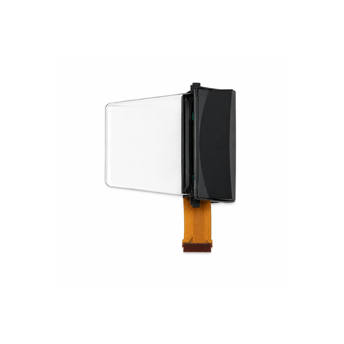
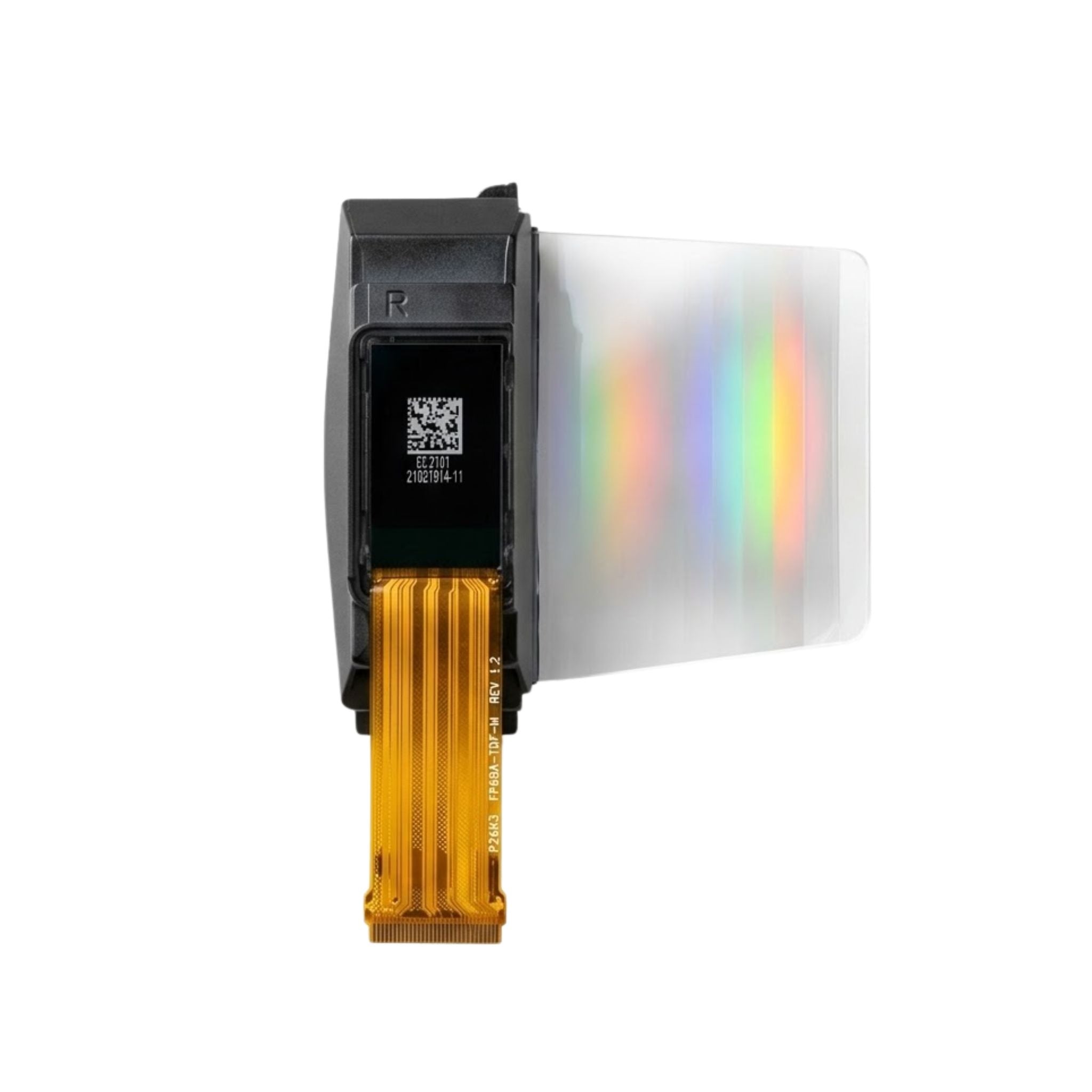
A screen module is a display panel shipped with its driver ICs, backlight or emissive stack, mechanical frame and a defined interface, so a product team can mount it and stream data to it instead of designing drive electronics. That packaging, not the glass, is what most buyers actually purchase, and it decides whether a design integrates in weeks or stalls in debug.
Panel versus module
Panel fabs sell glass. A bare panel carries the pixel array, the electrodes and very little else: no backlight, no timing controller, no connector that a microcontroller can talk to.
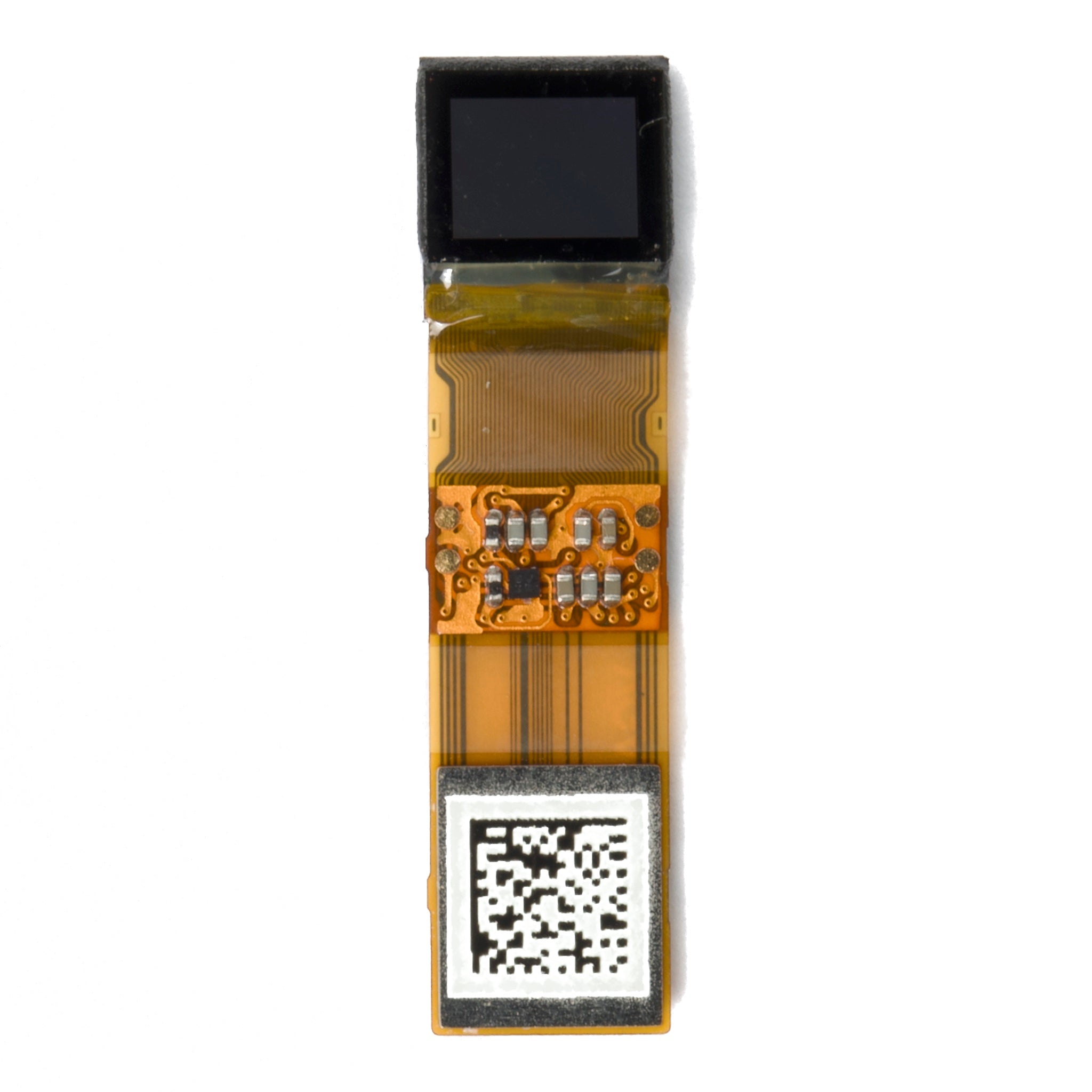
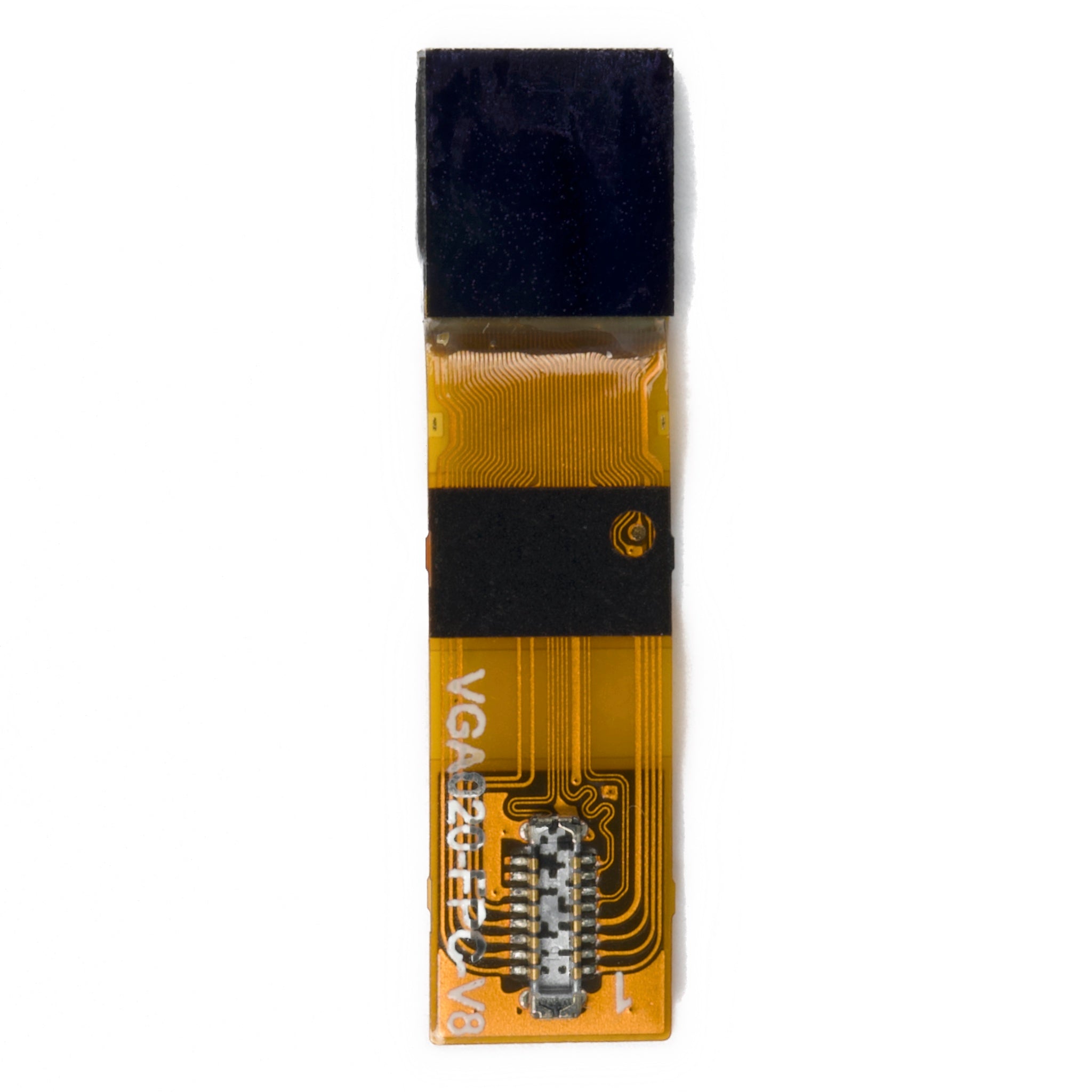
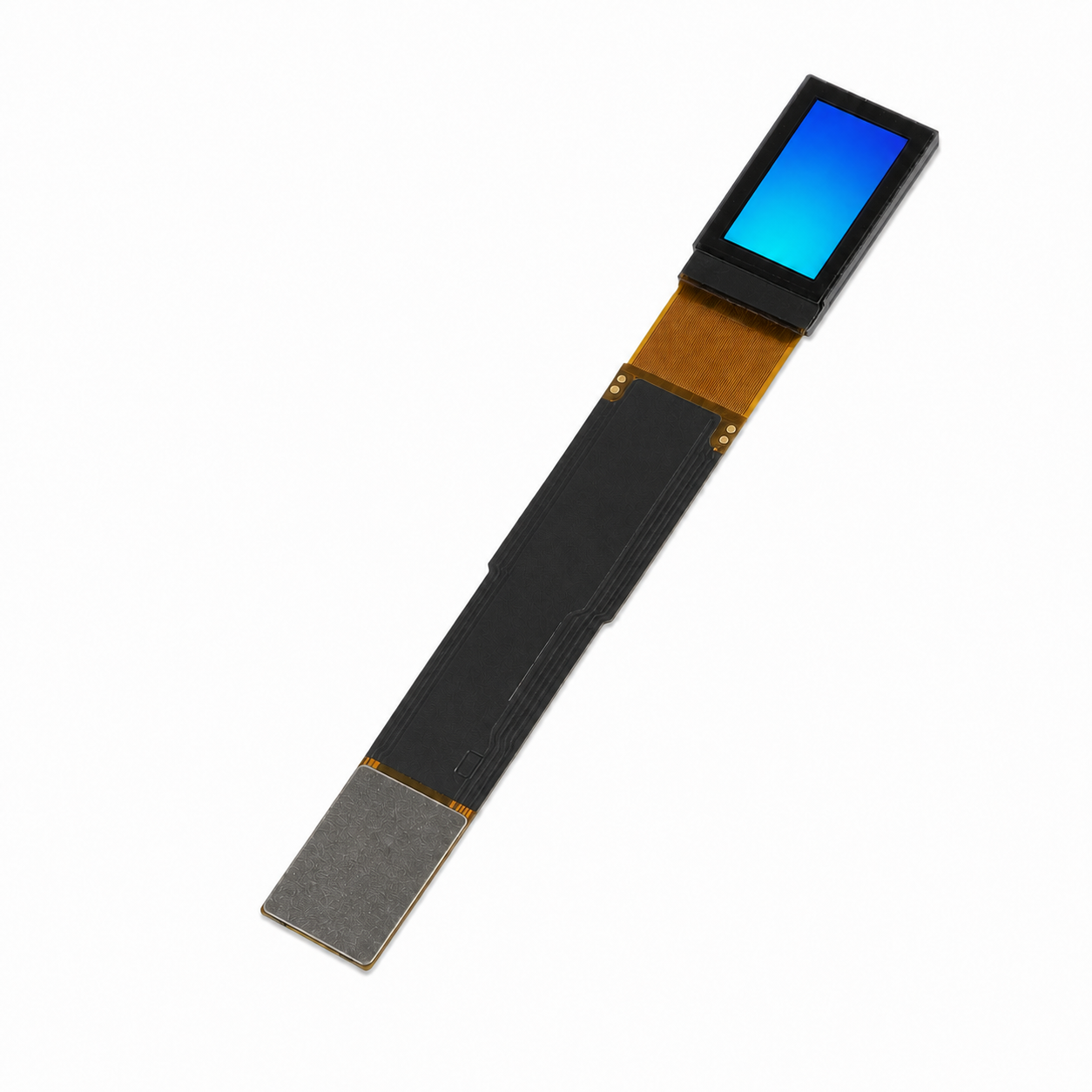
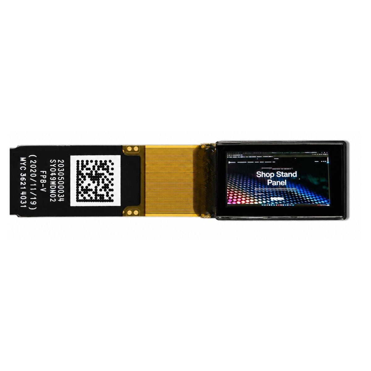
A module closes that gap. It adds row and column drivers bonded to the glass, a controller or bridge chip, a flexible printed circuit with a documented pinout, the optical stack, and a frame with mounting features. For an LCD the stack includes the backlight; for an OLED it includes the encapsulation that keeps oxygen and moisture away from the organic layers[2].
Two modules can carry identical glass and behave nothing alike. Change the backlight, the polariser, the driver's gamma tables or the bonding method, and brightness, contrast, power draw and cost all move. That is why a specification written around glass alone tends to disappoint.

What sits inside
An LCD module stacks a backlight, a diffuser, one or more brightness-enhancement films, a rear polariser, the TFT glass with its liquid crystal layer, a colour filter, a front polariser, and the driver electronics. Light from the backlight is modulated pixel by pixel; the panel does not emit on its own.
Driver bonding is the detail that most often decides module thickness and cost. Chip-on-glass places the die on the panel edge and suits compact, high-volume parts; chip-on-film moves the die to the flex and buys room for finer pitch and easier rework.
The pixel's state between refresh cycles is held by the pixel capacitor together with a storage capacitor. The liquid crystal does not store charge. It rotates polarised light in response to the field those capacitors maintain, and the analyser converts that rotation into a brightness value.
An OLED module removes the backlight. Each pixel contains an organic emitter and a drive transistor, so black is the absence of emission rather than a shutter closed over a lamp. That simplifies the optics and complicates the electronics, because every pixel now needs compensation for ageing and for threshold drift across the backplane.
Interfaces
Small modules expose SPI or an 8-bit parallel bus. Mid-size modules take parallel RGB, LVDS or MIPI DSI. Large industrial modules increasingly use embedded DisplayPort.
Bus choice follows arithmetic rather than preference. A 128×64 monochrome panel refreshed at 60 Hz in 1 bit per pixel needs roughly 0.5 Mbit/s, comfortably inside what a modest SPI clock delivers. Driving 480×272 at 60 Hz in 16-bit colour needs on the order of 125 Mbit/s, beyond what most SPI peripherals sustain, so that class of module moves to parallel RGB or MIPI.
Ask for the full timing diagram, not just the pin list. Setup and hold times, reset pulse width, and the order in which the logic rail and the panel rails come up are all part of the interface contract, and they explain most blank-screen first prototypes.
Backlight and brightness
Brightness is a system property. LED flux, light-guide efficiency, film gain, polariser transmission and pixel aperture ratio multiply, and the figure on the datasheet is that chain measured at one point under one drive current.
Native contrast comes from the liquid crystal mode and the optical structure, not from the backlight. Raising the backlight lifts white and black together, so their ratio barely moves. A module quoted at high brightness with no contrast figure is telling you half the story.
Touch
Touch arrives in three arrangements: a separate sensor laminated onto the module, an on-cell sensor patterned on the cover glass, or an in-cell sensor built into the display array. Separate sensors are the easiest to source and the thickest. In-cell designs save stack height and usually require the display and touch controllers to share timing.
Confirm who owns the flexible circuit. Two controllers on one flex is cheaper and mechanically simpler, but it couples your touch firmware to the display vendor's initialisation sequence.
Reading a datasheet
Most module datasheets are honest but incomplete, and the gaps fall in predictable places.
| Parameter | What the quoted value usually means | What to request |
|---|---|---|
| Brightness | Centre-point reading at nominal LED current, after warm-up | Minimum and average across the active area, plus current and temperature |
| Contrast | Static full-white and full-black fields in a darkened room | The measurement standard and the luminance of both fields[1] |
| Viewing angle | The angle where contrast falls to a stated ratio | Which ratio defines the limit, and whether colour shift is reported separately |
| Response | Grey-to-grey transition at room temperature | Transition pair, drive condition, and behaviour at the low end of the temperature range |
| Lifetime | Hours to a stated fraction of initial luminance at rated drive | Which fraction, which colour, and the drive current assumed |
Integration checks
- Power sequencing. Bring up the logic rail before the panel rails and switch the backlight last. Reversing that order can latch the driver into an undefined state that only a full power cycle clears.
- Flex and connector. Check bend radius, mating height and insertion force against your enclosure, and lock the connector type into the drawing so a substitute reel cannot arrive with a different footprint.
- Initialisation. Vendor register sequences are not interchangeable between driver revisions. Record the sequence with the module lot number.
- Thermal. An LCD loses contrast and an OLED accelerates ageing as the panel warms. Measure the module at the temperature your enclosure actually reaches, not on the bench.
LCD or OLED module
LCD modules remain the default where the image is mostly static, the duty cycle is long, or the unit price dominates. OLED modules win where the enclosure is thin, the content is dark, or the black level is part of the product's appearance. The trade-off is covered in more depth in our OLED collection.
Sizing follows the same logic. Character and small graphic modules with a fixed font controller suit instrument panels, while TFT modules suit anything that needs an image, and the module's interface, not its diagonal, usually sets the integration effort.
What to decide first
Fix the interface and the mechanical envelope before choosing a panel. A module is a contract between glass, optics, electronics and mechanics. Read it as a whole and the part behaves as specified; read only the diagonal and the brightness, and the surprises arrive at first light-up.
References
- ISO 9241-307:2008 — Ergonomics of human-system interaction — Part 307: Analysis and compliance test methods for electronic visual displays. International Organization for Standardization. https://www.iso.org/standard/40102.html
- Hilsum, C. (2010). Flat-panel electronic displays: a triumph of physics, chemistry and engineering. Philosophical Transactions of the Royal Society A, 368(1914), 1027–1082. https://doi.org/10.1098/rsta.2009.0247
Weiterlesen
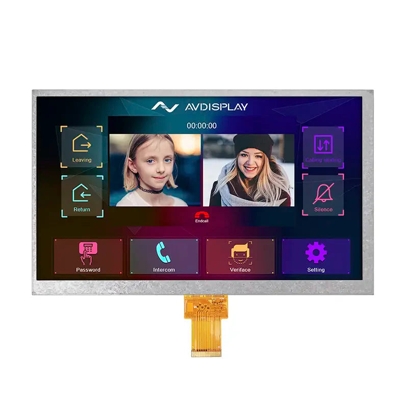
A TFT display module, short for TFT transistor, is a compact screen component that uses active-matrix technology , in which each pixel has its own.
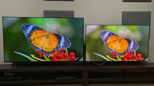
Choosing between OLED and DLED depends on needs: OLED delivers true blacks (infinite contrast ratio) with pixel-level dimming for rich colors, great for.
Hinterlasse einen Kommentar
Diese Website ist durch hCaptcha geschützt und es gelten die allgemeinen Geschäftsbedingungen und Datenschutzbestimmungen von hCaptcha.