



What is a TFT display module
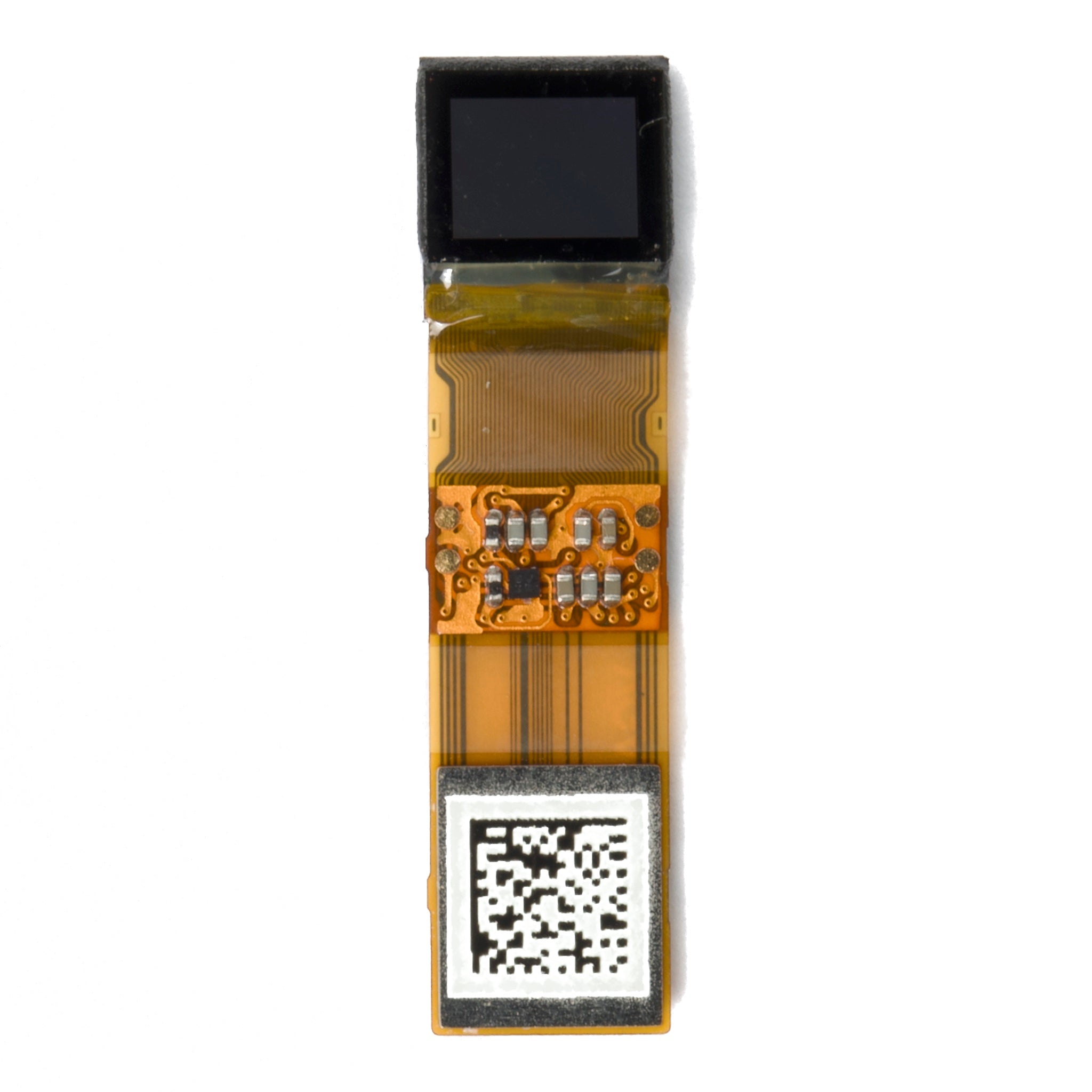
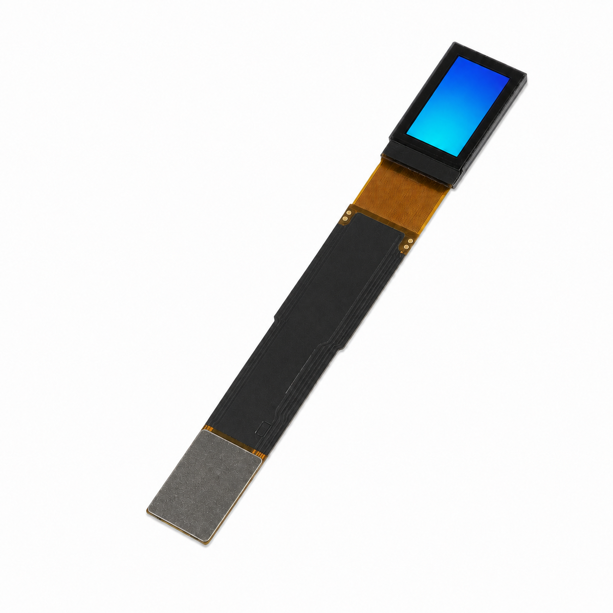
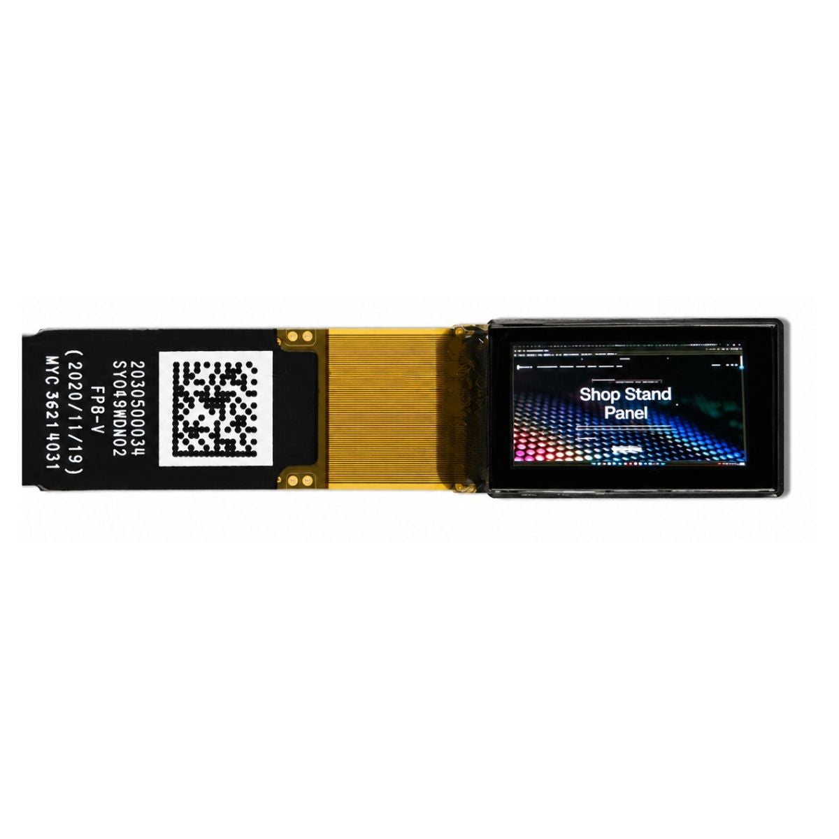
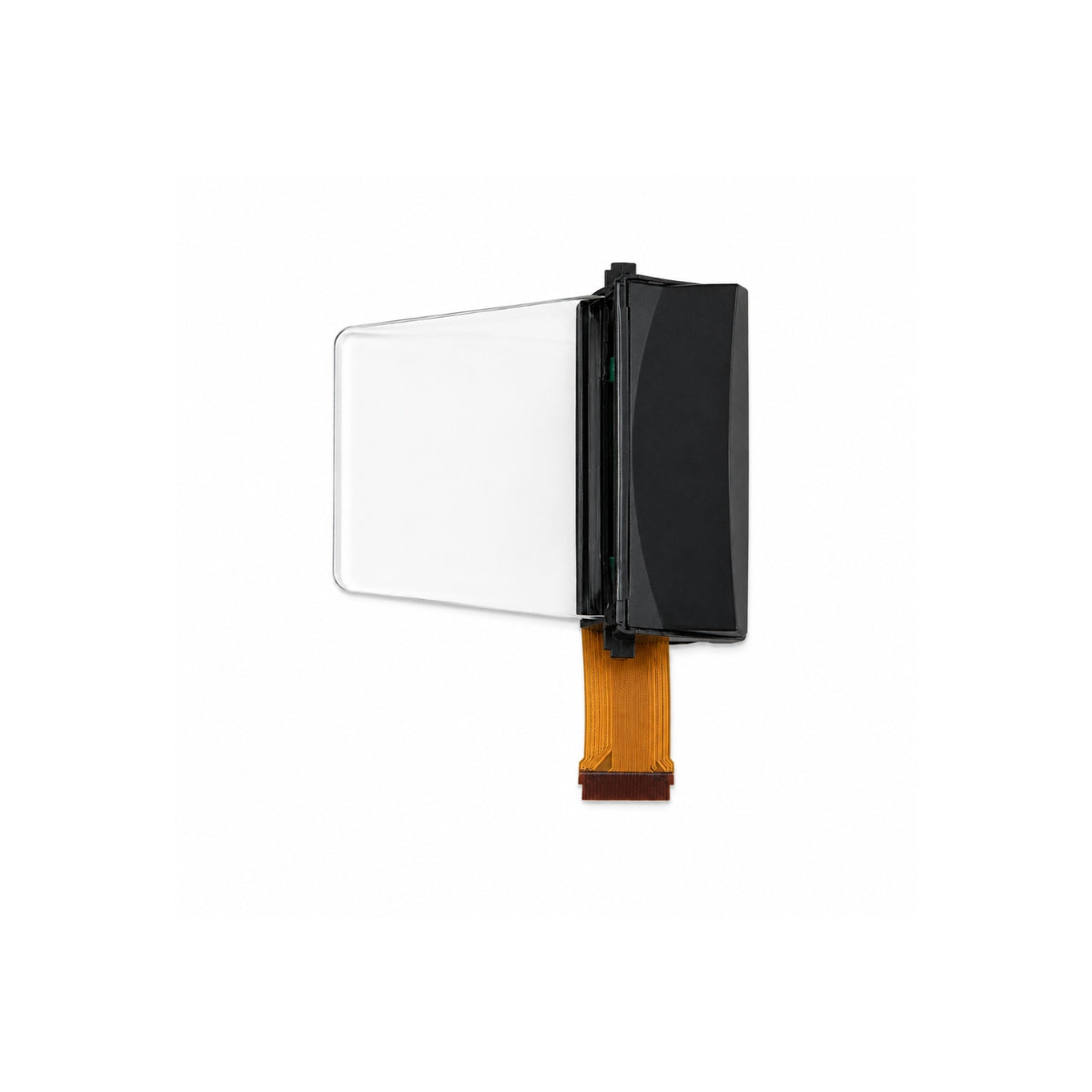
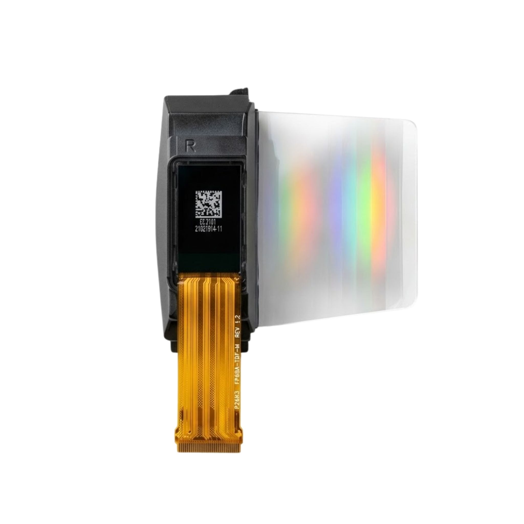
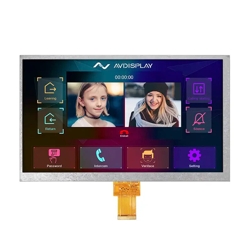
A TFT display module is a complete, testable display assembly rather than a bare panel. It combines a thin-film-transistor glass with a driver IC, a backlight, a flex circuit, and often a touch layer and cover glass, so a product team can connect power and a signal and see an image. The transistor array is what makes it active-matrix: every pixel has its own switch, so pixels hold their state while the rest of the screen is addressed.
Panel and module are not the same purchase
A panel is the glass: two substrates, the liquid crystal layer, the colour filter, the polarisers, and the transistor array. A module wraps that panel with everything needed to make it work in a product. The difference matters commercially, because a panel quotation and a module quotation are rarely comparable, and technically, because most field failures happen in the parts the module adds.
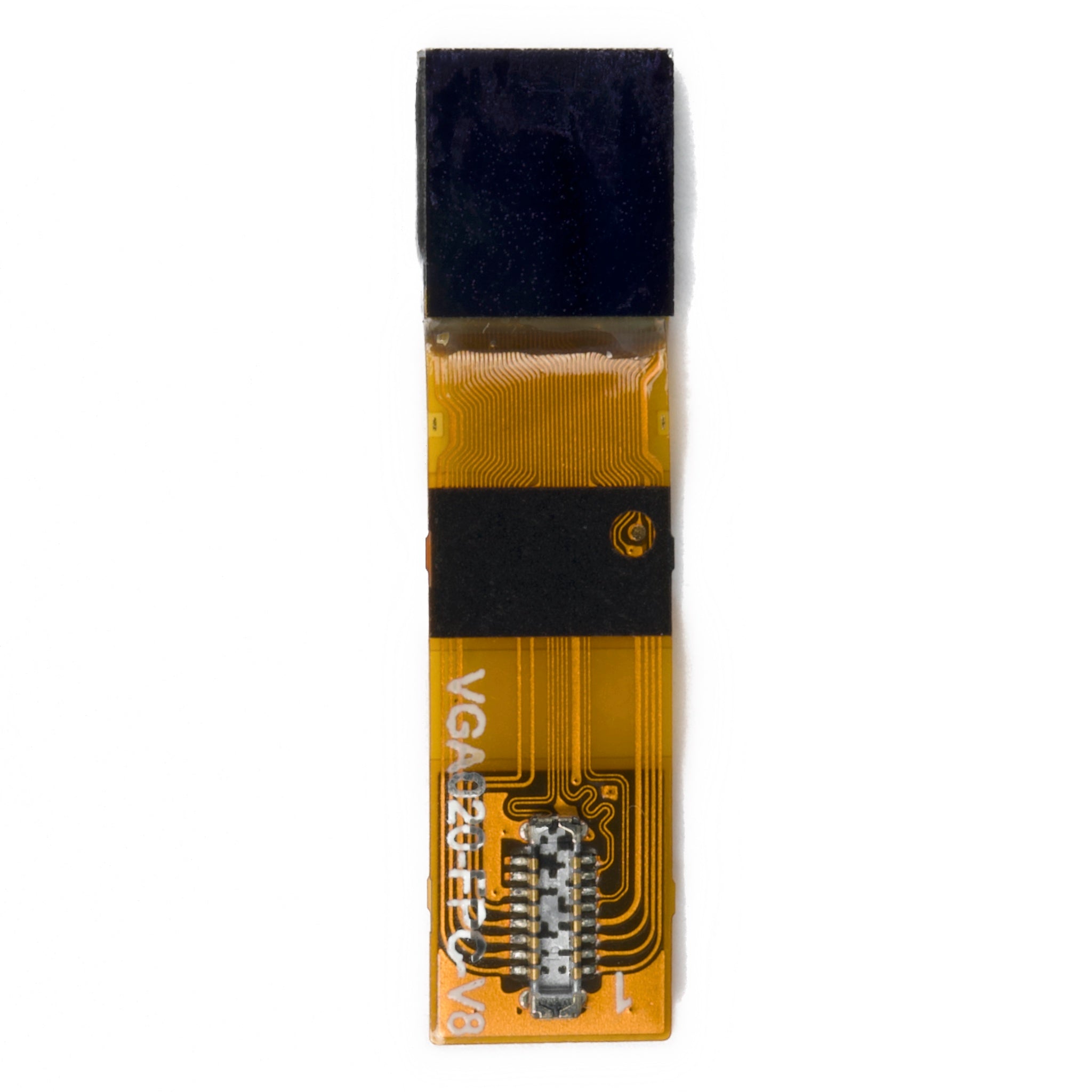
What a module normally contributes: the driver IC bonded to the glass, the flex tail that carries power and data, the backlight with its light guide and diffusers, a frame or bracket that sets the mechanical datum, and the connector. Additions such as a touch sensor, an optically bonded cover glass, an anti-glare treatment, or a cold-start heater turn a standard module into a custom one.
The layer stack, from the back
A backlight unit sits at the rear, either edge-lit with a light guide or direct-lit behind the panel. In front of it, a rear polariser, then the TFT glass carrying the transistor array and the pixel electrodes, then the liquid crystal layer, then the colour filter glass with the black matrix and the red, green, and blue filters, then the front polariser.
Tolerances stack across the layers. Cell gap uniformity controls contrast and colour; polariser alignment controls black level; the bond between the cover glass and the panel controls reflection and haze. A module that looks good on a bench can fail in a housing once the frame loads the glass, the backlight shifts, or the cover-glass bond bubbles at the edge.
Addressing and the storage capacitor
Rows and columns of address lines cross the array, and each intersection drives the gate of one transistor. When a row is selected, the transistors in that row conduct and the column voltages charge the pixel. When the row is deselected, the transistor turns off and the charge is held by the pixel capacitance in parallel with a storage capacitor, which is why the image persists while other rows are written.
That detail is worth stating precisely, because it is often described incorrectly: the charge is held by a capacitor, not by the liquid crystal molecules themselves [2]. The liquid crystal responds to the voltage it is given; it does not store it.
The transistor material sets what the array can do. Amorphous silicon is cheap and uniform enough for large areas but switches slowly. Low-temperature polysilicon switches far faster and is the usual choice where high pixel density or high frame rate is required, at the cost of more process steps. Oxide semiconductors sit between the two and are common where both moderate speed and low leakage are needed. The practical consequence for a module buyer is that the backplane technology limits the achievable resolution and refresh rate long before the liquid crystal does.

Driver, interface, and bandwidth
The driver IC converts the incoming image stream into the voltages written to each column, and it generates the timing that selects rows. On small modules it is usually bonded directly to the glass, which is why the flex tail and the bond pad layout are part of the mechanical design rather than an afterthought.
Interface choice is a bandwidth decision before it is a convenience decision. A serial peripheral interface needs few pins and is easy to route, but whether it can carry a given resolution and colour depth at a given frame rate depends on three things together: the frame rate required, the bits per pixel, and the clock the interface can actually sustain. Increase any one and the others fall. Parallel RGB avoids the clock limit at the cost of many pins and a short cable. MIPI DSI, LVDS, and embedded DisplayPort move the problem to a high-speed differential pair and are the usual answer above a few inches.
Ask for the interface timing diagram, not just the connector pinout: it defines the blanking intervals, the pixel clock, and the sync polarity, and a mismatch there produces a shifted or rolling image that looks like a hardware fault.
Backlight, dimming, and brightness
The backlight usually dominates both the power budget and the brightness specification. Brightness quoted in candelas per square metre is only comparable when the measurement condition is stated: after warm-up, at the specified drive current, at the centre of the panel, and with the dimming set to maximum [1].
Dimming method matters more than most specifications admit. Many modules dim by pulse-width modulation, switching the backlight on and off faster than the eye can resolve; others reduce the drive current, and many combine both, using current reduction over part of the range and PWM below it. The difference is visible as flicker in peripheral vision, in photographs, and on camera, and it matters for equipment used for long shifts. If flicker is a concern, specify the dimming method and the minimum dimming level rather than accepting "PWM" or "DC" as a label.
Brightness also trades against lifetime and heat. Running a backlight at maximum raises the junction temperature of the light sources, and output falls over time as a function of that temperature. A high-brightness module in an enclosed housing needs a thermal path, and the lifetime figure should be quoted at the drive current the product will actually use.
Resolution, density, and viewing distance
Pixel density is the diagonal in pixels divided by the diagonal in inches, and it is only useful when paired with a viewing distance. A density that looks coarse at arm's length looks fine across a control room. That is why the same resolution can be right for a handheld and wrong for a wall panel.
Three practical rules follow. Match density to the closest expected viewing distance rather than the average. Check that the interface and the backplane can both support the resolution at the frame rate, since either can be the limiting part. And check the sub-pixel structure if the content includes small text, because a panel with an unusual sub-pixel layout can render fine type worse than its density suggests.
Industrial and medical requirements
Modules for equipment carry requirements that consumer panels rarely see. Operating temperature range is the first: liquid crystal response slows in the cold and contrast shifts at the top of the range, and a heater or a compensated mixture may be needed. Storage temperature, humidity, and vibration follow.
Optical bonding is the second. Bonding the cover glass to the panel with an index-matched adhesive removes an air gap, which reduces internal reflections and improves readability in sunlight and behind a window. It also stiffens the assembly, which changes how the module behaves under impact.
The third is documentation. A medical or industrial buyer needs the incoming inspection criteria, the measurement conditions, and a change notification process, not just a datasheet. Our industrial display modules are specified on that basis, and the same questions apply to any TFT LCD module being qualified for a long-life product.
What to specify
Write the requirement as a set of coupled numbers, because the module is a system. Active area and resolution together, so density follows. Frame rate and colour depth together, so the interface can be checked. Brightness with its measurement condition and dimming method. Contrast as a native figure, not a dynamic one. Viewing angle with the colour tolerance at that angle. Operating and storage temperature. Interface type with the timing diagram. Touch type, cover glass thickness, and bonding method. Lifetime with the drive current attached.
A TFT module is a display plus everything that makes it usable, and the added parts carry most of the risk. Specify the interfaces and the measurement conditions before the price, and the quotation you receive will describe a product rather than a panel with ambitions.
References
- ISO 9241-307:2008 — Ergonomics of human-system interaction — Part 307: Analysis and compliance test methods for electronic visual displays. International Organization for Standardization. https://www.iso.org/standard/40102.html
- Hilsum, C. (2010). Flat-panel electronic displays: a triumph of physics, chemistry and engineering. Philosophical Transactions of the Royal Society A, 368(1914), 1027–1082. https://doi.org/10.1098/rsta.2009.0247
Weiterlesen
An OLED display module is a self-emissive panel using organic compounds to emit light when electrified, boasting infinite contrast ratios (up to.
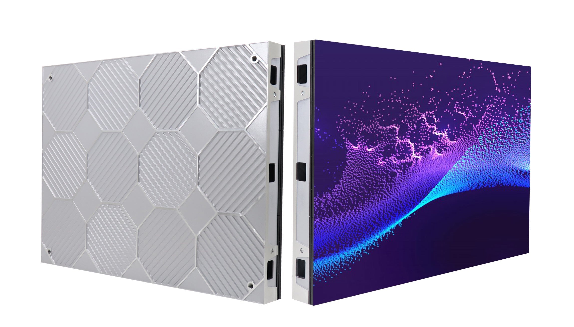
A screen module, a self-contained display unit integrating components like LCD/LED panels, driver circuits, and sometimes touch sensors, typically.
Hinterlasse einen Kommentar
Diese Website ist durch hCaptcha geschützt und es gelten die allgemeinen Geschäftsbedingungen und Datenschutzbestimmungen von hCaptcha.