









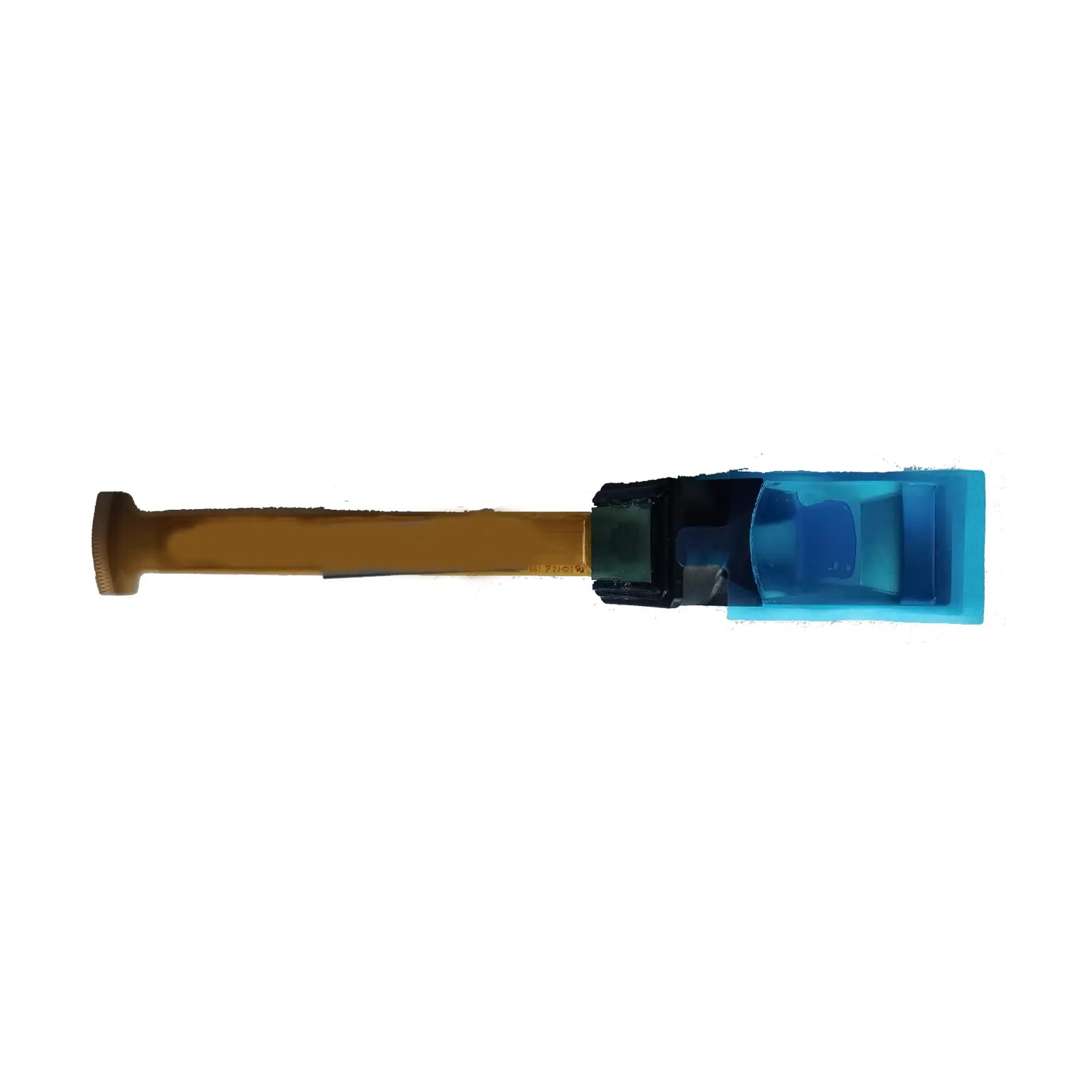
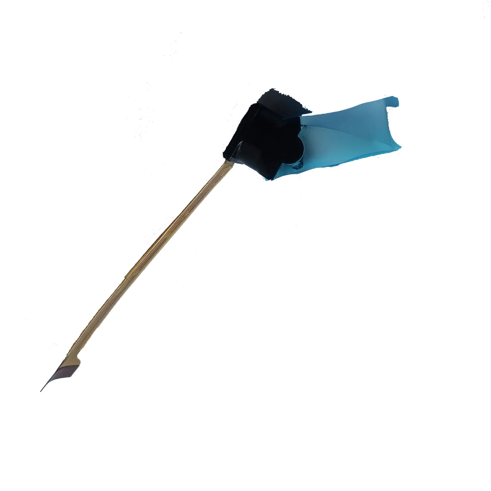
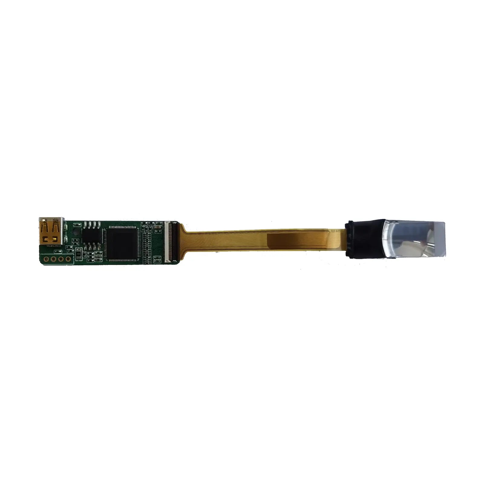
DM-ADTTR-024 Micro OLED Display Module
0.23-Inch Micro OLEDoS Display, 640(RGB) × 400, Up to 2400 cd/m², 50/59.94/60 Hz
The DM-ADTTR-024 is a 0.23-inch active-matrix color Micro OLED panel module based on a single-crystal silicon transistor backplane. Its panel driver and logic driver are integrated on-chip, helping reduce the size and component count of compact display and optical systems.
The native 640(RGB) × 400 format contains 256,000 full-color pixels and 768,000 RGB sub-pixel dots. Based on the nominal 0.23-inch diagonal, the calculated pixel density is approximately 3,280 PPI. Mechanical tolerances, power conditions, timing registers and optical alignment must be checked against the current controlled documentation before production design.
640 × 400
Native full-color resolution
Up to 2400 cd/m²
Mode 4 maximum panel luminance
≥10,000:1
Specified minimum contrast ratio
50 / 59.94 / 60 Hz
Supported frame-rate modes
Calculated Engineering Values
Native Aspect Ratio
16:10, calculated from the 640 × 400 active-pixel format.
Full-Color Pixels
640 × 400 = 256,000 full-color pixels.
RGB Sub-Pixel Dots
640 × 400 × 3 = 768,000 dots, commonly shown as approximately 0.77M dots.
Approximate Pixel Density
Approximately 3,280 PPI, calculated from the diagonal pixel count and nominal 0.23-inch display size.
Estimated Active Format
Approximately 4.96 mm × 3.10 mm when estimated from a 0.23-inch diagonal and 16:10 ratio. Do not use this calculated value as a tooling dimension.
Production Verification
Confirm the active-area position, FPC tolerance, optical center, connector orientation, timing registers and power sequence with the latest controlled drawing and integration data.
Optical, Electrical and Interface Specifications
| Parameter | Specification | Engineering Note |
|---|---|---|
| Display Technology | Active-matrix color OLED / Micro OLEDoS | On-chip driver using a single-crystal silicon transistor backplane |
| Nominal Diagonal | 0.6 cm / Type 0.23 | Intended for compact, magnified or small-monitor applications |
| Native Resolution | 640(RGB) × 400 dots | 16:10 native format with 256,000 full-color pixels |
| Number of Dots | Approximately 0.77M RGB dots | 640 × 400 × 3 = 768,000 RGB sub-pixel dots |
| Calculated Pixel Density | Approximately 3,280 PPI | Calculated from the nominal 0.23-inch diagonal and 640 × 400 native format |
| Luminance Mode 4 | 1600 min. / 2000 typ. / 2400 max. cd/m² | Datasheet measurement at a panel temperature of 40°C, all-white display and screen-center measurement point |
| Contrast Ratio | 10,000:1 minimum | Measured using all-white and all-black display conditions |
| Supported Frame Rates | 50 Hz, 59.94 Hz and 60 Hz | Supported across the documented 16:9, 4:3 and 16:10 timing modes |
| Native Display Mode | 640(H) × 400(V), 16:10 | Additional documented input formats include 640 × 360 and 532 × 400 |
| Input Interface | Parallel RGB 24-bit, YCbCr 24-bit and YCbCr 16-bit | Register settings, input mapping and timing must match the host controller |
| Digital Power Rails | VDD1: 1.8 V; VDD2: 10 V | Separate VCCP and VCATH supplies are also required; confirm their controlled limits before schematic release |
| Driver Integration | Panel driver and logic driver integrated | Reduces the requirement for an external display-driver IC |
| Scan Direction | Up/down and right/left selection | Useful when matching the panel orientation to mirrors, prisms or lens assemblies |
| Power-Saving Function | Power-saving mode supported | Confirm register behavior and wake sequence during firmware validation |
| Temperature Compensation | Integrated luminance temperature-compensation function | The VCAL output can be used for panel-temperature monitoring according to the documented register procedure |
| Operating Limits | Confirm with the current controlled specification | Do not infer operating temperature, storage temperature or absolute maximum ratings from nominal design values |
Architecture and Integration Details
Silicon Backplane OLED
The emissive OLED pixel array uses a single-crystal silicon transistor backplane. This architecture supports a high pixel density within the compact Type 0.23 format.
Parallel Video Inputs
The documented input options include RGB 24-bit, YCbCr 24-bit and YCbCr 16-bit. Input format, synchronization and data mapping should be fixed before the controller design is released.
Power-Rail Planning
The pin assignment includes VDD1, VDD2, VCCP, VCATH and ground connections. Sequencing, ripple, discharge behavior and rail tolerances require controlled design data.
Orientation Control
Selectable up/down and right/left scanning helps accommodate optical inversion, mechanical orientation and compact board placement.
Optical Design Notes
Magnified Viewing
The calculated pixel density is approximately 3,280 PPI, but perceived sharpness also depends on lens MTF, magnification, optical focus, eye relief, distortion correction and alignment tolerance.
System-Side Brightness
The 2400 cd/m² figure is the documented maximum for Mode 4, not a guaranteed eye-side value. Final brightness is reduced by lens, prism, polarizer, combiner or waveguide transmission losses.
Contrast and Black Level
The OLED panel emits light without a separate backlight. The specified minimum contrast ratio is 10,000:1 under the datasheet measurement method.
Design-In Checklist
Confirm Video Timing
Lock the input format, pixel clock, active-pixel count, total timing, synchronization polarity, reset sequence and register initialization before PCB release.
Validate Every Power Rail
Measure the VDD1, VDD2, VCCP and VCATH rails during startup, steady-state operation, shutdown and rapid power cycling.
Review the Mechanical Drawing
Verify the display center, FPC dimensions, connector pitch, contact orientation, bending area, optical axis and enclosure keep-out zone.
Control Production Documents
Record the datasheet revision, initialization table, drawing version, approved sample, optical test conditions and supplier change-notification requirements.
Application Fit and Verification Points
Head-Mounted and Near-Eye Displays
Suitable for evaluating compact head-mounted displays and enclosed near-eye viewers. Verify eye relief, lens magnification, focus, eye-box size, optical distortion and enclosure temperature.
Viewfinders and Compact Monitors
The documented application range includes viewfinders and small monitors. Validate frame timing, color mapping, brightness mode, scan direction and optical alignment in the assembled product.
See-Through AR Evaluation
Suitability for see-through AR cannot be judged from panel luminance alone. Calculate eye-side luminance after optical losses and test the complete system under its intended ambient-light conditions.
Technical Documentation and Procurement
Documented Product Data
The available specification identifies the display format, luminance modes, contrast, supported frame rates, input formats, scan-direction control, temperature compensation and power-pin functions.
Engineering Review
Before design-in, review the controlled timing data, register settings, mechanical drawing, connector details, optical test method, power requirements and approved initialization sequence.
Procurement Verification
Confirm sample status, production lead time, packaging, ESD requirements, lot traceability, warranty terms, revision control, product-change notification and long-term supply status.
Mechanical Reference
Module Dimension View

Connector and Assembly Reference

These images are suitable for preliminary evaluation. Production tooling and optical alignment should use the latest controlled drawing package, including all dimensions, tolerances, connector details and applicable package variation.
Download the Datasheet and Confirm System Integration
Review the official specification before PCB layout, firmware release or optical tooling. Confirm the interface timing, register settings, power requirements, mechanical drawing and optical measurement conditions.
For near-eye applications, evaluate the completed optical path rather than relying only on panel-side luminance.
Download Official Datasheet